1
Collaborative Engine for Distributed Mechanical Design
Qianfu Ni and Wen Feng Lu
Abstract Effective collaboration is essential for engineers at geographically dispersed locations to accomplish good design with less iteration. Over the last several years, more and more efforts have been put into such research as many industries have distributed their product development to locations with knowledge force. This paper presents a collaborative engine to facilitate collaborations among distributed mechanical designs. Using component-based software technology, collaboration functionality is developed into a set of groupware that makes the collaborative engine applicable to develop new collaborative applications or integrate legacy applications into collaborative environments. An XML-based information representation is developed to streamline the information transmission within the distributed environment. A case study is carried out to show how this engine facilitates designers to collaboratively create a 3D solid model of a same part in real time.
Keywords collaboration, distributed design,
collaborative engine
INTRODUCTION
As global market is becoming more and more competitive and customer requirements are more and more specific, production in many industries is changing from store to make-to-market and further to make-to-order. Products may need to be designed and produced specifically based on customer requirements. In order to survive in such competitive market with high quality products, enterprises need to provide channels for customers to be involved, especially in the early stage of product development. It is often stated that roughly 70 percent of the total life cycle cost of a system is determined during conceptual phase of the product development process. Very few
Qianfu Ni is with Manufacturing Information Technology Division, Gintic Institute of Manufacturing Technology, 71 Nanyang Drive, Singapore 638075 Wen Feng Lu is with the Innovation in Manufacturing Systems and Technology (IMST), Singapore-MIT Alliance (SMA), N2-B2c-15, Nanyang Technological University, Nanyang Avenue, Singapore 639798, email: [email protected]
traditional CAD tools are available to support the early stages of design [1]. On the other hand, Finger and Dixon also stated that an important area that has received little attention to date is the creation of design environments that integrate available tools into a consistent system to support the designer [2, 3].
Designing is a process of converting
information that characterizes the needs and requirements for a product into knowledge about a product [4]. Designers often complain that they spend a lot of time searching for information and knowledge, but could not get the desired information and knowledge. It is claimed that about 70% of time during the design stage are spent on searching for information [5]. Design process has been considered by many investigators as a decision-making process, which is very information intensive. To make decision in design, lots of information needs to be analyzed, such as customer requirements, market trends, existing products data, materials, manufacturing capabilities, assembly, and social culture [6]. Hence, the design process often involves all kinds of experts with different intentions, backgrounds and circumstances who usually are geographically dispersed at different locations. In such scenario, communication among team members is very critical to ensure that the design can be carried out successfully and effectively. In this respect, collaborative design is recognized as an effective solution for distributed design. It allows geographically dispersed designers with different expertise to be involved in design at the same time with remarkably short communication time. It also facilitates designers to cooperatively make decisions with consistent information, and maximizes information sharing. Design is known to involve lots of iterations and corrective work. Many design flaws are often discovered in manufacturing stage, and some may even be found after the products are delivered to customers. The corrective redesign effort is usually extremely expensive. The collaborative design enables different expertise besides designer, such as manufacturing engineers, customers and suppliers, to be involved in the design process. This provides a means to enable
design flaws and shortcomings to be identified in the early stage. As a result, the number of design iterations can be minimized, and the rework efforts could be reduced.
There are two approaches to realize the
collaborative design. One is to develop new computer-added software with support to the collaborative design. The solution based on this approach can provide powerful capabilities to fully support the collaborative design, but it will be very costly. This kind of software is not available in the market yet, but some software companies, such as PTC and Unigraphics, which are vendors of Solid Modeling and Product Data Management (PDM) software, already demonstrated some prototypes of such systems. Another approach is to develop collaboration functions based on the existing software. Comparing to the former, this approach requires less effort and time to realize.
Many researchers have been working on
collaboration enabling technologies or infrastructure. Uwe Jasnoch et al proposed a Virtual Prototyping environment in which each participant can focus on his/her own area of work [7]. They put more focus on product model based on STEP and concurrent information access. Gun-Dong F. Pahng et al presented a WEB-based collaborative design model, which focuses on decision support based on problem decomposition [4]. Hardwick et al developed an information infrastructure architecture that enhances collaboration between design and manufacture firms [8].
In face to face collaboration, designers have a variety of ways to communicate with each other. Besides speaking to each other, eyes contact, face expression, and gesture could support effective communication. Although it is difficult to provide such comprehensive mechanism for communication in a collaborative environment for solid modeling, it is possible to develop some fundamental supporting functions, such as event triggering, notification messaging, and task management, to enhance close interaction between collaborative users. This paper develops a collaborative engine with such an environment in mind that collaborative users are aware of each other so that they feel that they are working collaboratively. In order for the collaborative engine to be easily utilized to develop new applications or integrate legacy application into a collaborative environment,
collaboration related functions are abstracted and modeled into a set of groupware based on component software technology. An information representation is also developed using Extensible Markup Language (XML) to streamline the information transmission through the engine. This collaborative engine is employed in a case study to develop a collaborative working environment in which designers are able to collaboratively work on mechanical design in real time.
ISSUES IN NETWORK-BASED COLLABORATION
Traditionally, communication within design teams can happen in many different ways, such as paper-based documents, face to face meeting, telephone conference, fax, and email. Such communications between designers in different locations could be time consuming. Designers today have to work independently as well as collaboratively. Each designer has his/her own role so that he/she can only access limited information and will only be notified with related events and activities. In a network-based collaboration, collaboration processes could become more complicated. Different designers could be involved in the same task or interdependent tasks. It is important for network-based collaboration to build a clear boundary between different designers to ensure that designer could work independently or cooperatively when necessary. It is equally critical for the network-based collaboration to provide capabilities to streamline design activities, control information access, and manage events and messages within the environment.
In order to assist users to share information and to work in a collaborative way, the collaborative engine is modeled based on the following requirements.
1. Enable real-time communications;
2. Support multiple users working on a same task at the same time;
3 . Maintain independence of individual user within the working environment;
4 . Provide an effective and secure information sharing;
5 . Provide a means to organize meetings and discussions;
6 . Facilitate development of collaboration-supported applications and integration of
legacy applications into a collaborative environment
XML-BASED INFORMATION REPRESENTATION At present, most of distributed computing systems are constructed based on heterogeneous platforms. For a distributed system that supports a heterogeneous platform, it is essential that information transferred within the system should be acceptable to each platform. Apparently, object-based information transmission mechanism can not function because objects are language and platform dependent. Hence, it is necessary to design a commonly acceptable information transmission approach for the collaborative engine. For the engine, a metadata-based approach is adopted here to streamline the information transmission. The term “metadata” is widely used, but no apparent formal definition is formed within the research community. ISO description 11179 defines metadata as the information or documentation, which makes data sets understandable and sharable for users [9]. In this paper, we simply define it as a set of terms that are used to describe data to enable the data to be commonly understood within an organization or a system.
XML is a technology most suitable for
definition of metadata currently. XML is one of the most significant developments of the computer industry since the World Wide Web and Java moved to their present positions of importance [9]. XML was originally developed for integration of legacy systems based on different platforms. XML-based matedata is developed to transmit information within the collaborative environment.
Information is transmitted using objects if the platforms are the same. This is the most efficient way, as it does not need any transformation. As shown in Figure 1, information will be transmitted using object from module 1 to module 2 directly within client 1. If information needs to be transmitted to a different platform, it is first transformed intoan XML document before being transferred to the collaboration engine. The engine can do some processing if necessary. After that, the information is broadcasted to related clients on different platforms.
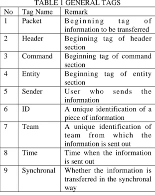
Fig. 1 Information transmission model XML-based information to be transferred to other platforms contains three sections: header, command and entity. Header section provides overall description of the information contained in the entity section. Command section includes information indicating which actions are performed to the entity. Entity section contains the actual information to be transferred. XML uses tags, which can have attributes to precisely describe the tags, to serve as metadata in XML Documents. According to roles of sections, XML tags are categorized into three classes: general tag, command tag and entity tag. Tables 1, 2 and 3 show part of the tags defined. Tag Packet is the outer most tag, which wraps other tags. Tag Packet has an attribute named type, which indicates the type of information packet, such as action, notification, or message. For entity section, many tags needed to describe different entities which should be developed based on specific applications.
TABLE 1 GENERAL TAGS No Tag Name Remark
1 Packet B e g i n n i n g t a g o f information to be transferred 2 Header Beginning tag of header
section
3 Command Beginning tag of command section
4 Entity Beginning tag of entity section
5 Sender User who sends the
information
6 ID A unique identification of a piece of information
7 Team A unique identification of team from which the information is sent out 8 Time Time when the information
is sent out
9 Synchronal Whether the information is transferred in the synchronal way 1, 2: Function modules 3: information object 4: XML translator Client 1 2 1 3 Engine Preprocess 4 Client 2 2 1 3 4
TABLE 2 ACTION TAGS No. Tag Name Remark
1 Add Action “add” takes place to the entity
2 Modify Action “modify” takes place to the entity
3 Delete Action “delete” takes place to the entity
4 Save Action “save” takes place to the entity
5 Open Action “open” takes place to the entity
6 SaveAs Action “save as” takes place to the entity
7 View Action “view” takes place to the entity
8 CheckIn Action “check-in” takes place to the entity
9 CheckOut Action “check-out” takes place to the entity
TABLE 3 ENTITY TAGS No. Tag Name Remark
1 Feature A design feature
2 File A file
3 Document A document
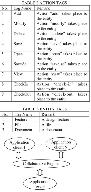
Fig. 2 Collaborative Engine works as a bridge FRAMEWORK OF COLLABORATIVE
ENGINE
The collaboration functionality is extracted and developed into a collaboration engine that acts as a bridge between application clients and a server, as shown in Figure 2. A set of remote interfaces, which can be used to invoke functions provided by the engine, is exported for application clients to communicate with the collaborative engine and be integrated into a collaborative environment. In an distributed application, an application server andclients can communicate with each other through these interfaces.
In a network-based environment, collaboration between two designers in geographically dispersed locations may not function well. This is certainly a barrier to information capture and communication. The collaborative engine presented here tries to provide an environment, which pushes more relevant information to users as well as enables users to have a feeling that other users are “around” in the environment in the environment. In the engine, connection functions are provided for users to enter or exit the environment. An event triggering mechanism is established to push information to related users and notify users what’s happening in the environment. It also assists the users to filter events that they want to publish or subscribe. Task management gives the users a sense of what’s going on in the environment, where they are and how they link to others. The users can talk to each others through messages, remind others, make an appointment by sending notification, or organize discussions among a group of people.
Using component-based technology, the
collaborative engine is modeled as a set of groupware based on multi-tier architecture that makes the engine easy to be implemented and used. As shown in Figure 3, each factor and service is designed as a stand-alone component that can communicate with other components. Interfaces are defined and served as the protocols of communication among the components. The interface tier exports functions of the collaborative engine for application development and integration. The application tier provides functions, exported by the interface tier, to enable and manage collaboration. The service tier provides functions to support the application tier. The database tier maintains the data needed for managing collaboration.
4.1 Application tier
Application tier tries to provide all kinds of functions to construct and manage an environment that enables users to be aware of others and the environment. In this tier, each factor provides functions to support collaboration for certain aspect. A user is connected to the collaborative engine through connection factor. Then he/she might be involved in a task using task factor. When he/she does something, real-time factor can notify other clients in an on-line manner. Theenvironment Application server Application client 1 Collaborative Engine … Application client N
also notifies him/her when something happen in the environment.
4.1.1 Connection Management
In a collaborative environment, it is very important to manage on-line users. Access control, team session, task session and event management depend largely on on-line user management.
The environment management and activity tracking also need support from on-line user management. The connection factor provides log on or log out methods for clients to connect or disconnect from the collaborative engine. When a user logs on the server, he/she will be transformed to an on-line user. At the same time, a user session is constructed and attached to the user session. In fact, most user-related functions work based on user sessions rather than users information itself because a user can log onto the server using different roles at the same time. 4.1.2 Event Management
The collaboration environment should not make user operations complicated. Users in the collaborative environment should work as if they worked independently. Users also can join or exit the collaborative environment easily. Event delegation technology, which enables flexible integration, is adopted to facilitate communication among users so that independence of individual users can be maintained. Event management functions are separated into two components: event factor and event service. The event factor provides functions for users to define the events he/she would like to publish, and the events he would like to receive. Event service is responsible for broadcasting events to relevant users.
4.1.3 Real-time Factor
The real-time factor can accept a request to broadcast real-time events to relevant users. The event can be broadcasted synchronouslyo r asynchronously depending on the value of the attribute “synchronal” (Table 1). If a targeted user is not on-line, the real-time event can be transformed to a message or task, which can be
Team Session Session Service User Session Session Manager Object Service Object Container Object Creator Object pool Interface to Server Real-time Factor Discussion Factor Task Factor Message Factor Connection Factor Event Factor Event Off-line User Task Event Queue Event Sender Event filter Event Service On-line User Task Session
Unified Data Access
Service tier Database tier Application tier Interface tier
persisted in a database. This user will be able to see the event immediately when he/she logs onto the system later. If an application attempts to realize real-time collaborative tasking, each client should refer to the interface exported from this factor. When something happens in an individual client, the real-time factor will notify others with necessary information.
4.1.4 Task Management
The task factor’s responsibility is to manage task-related businesses, such as creation of new tasks, distribution of tasks or cancellation of tasks. It also provide some functions to monitor tasks, for example, what tasks are planned in the system, what tasks are ongoing, or what tasks on-line users are performing.
4.1.5 Discussion Management
The discussion factor simulates a meeting room in the real world. It is armed with functions to open a meeting room, close the door of a meeting room, or to dispose a meeting room. It also manages the owner of each meeting room and his rights indicating who can join in the meeting. The message factor is a simple facilitator that helps users send messages to the environment. Users can use it to call for a meeting, to make an appointment, and to issue a notice.
4.2 Service tier
Service tier organizes common functions into three services to support the application tier. Session service is built to maintain a boundary between users, teams and tasks. It provides an independent working space with awareness of other users. Event service can accept requests from application tier or session service to broadcast events within the environment. Object service provides object management functions for the whole engine.
4.2.1 Event Service
The event service maintains an event queue. All events to be issued will be put into the queue before they are sent out. The event service checks the value of the attribute “synchronal”, then uses a corresponding way to broadcast the events. Before sending an event, the event service also filters events according to the user subscription. An event will only reach a user
who subscribes to it. If a user who does not subscribe to an event is targeted, a message will be sent to him/her, and the message is also persisted in a database for possible checking in future. If a targeted user is not on-line, a message or a task will be generated and persisted for him/her.
4.2.2 Session Service
Session is a very important concept to a
collaborative environment. Session service cooperatively works with the event factor to build a boundary between teams, tasks and users. When a user logs onto the engine, a user session will be created to uniquely identify the user. While the user is involved in a task, the task factor will notify the session service. The session service will create a task session and associate the user session with the task session. The session service also activates all teams related to this task and creates sessions for the teams. Any activity that happens to the task session will be visible to all on-line users who belong to the teams related to the task. A task or message will be created for corresponding off-line users. 4.2.3 Object Service
Object service provides generic functions to manage objects for the engine. The object container has capabilities to manage objects via the object pool. When a service tries to retrieve an object, the object container will first look for the object in the object pool. If the object is found, it directly returns the object to the service. Otherwise, the object container will activate the database access component to retrieve the relevant data from the database, request the object creator to construct the object using the data, and then return the object to the service. At the same time, it also puts the object into the object pool for later use. This mechanism will maximize information sharing. Another advantage is that the object model will be unified.
CASE STUDY: COLLABORATIVE MECHANICAL DESIGN 5.1 Scenario
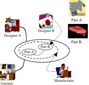
A prototype of this collaborative engine has been developed for 3D mechanicaldesign. A scenario is shown in Figure 4 to illustrate how the collaboration engine is used for collaborative
mechanical design. A customer is connected to designers and the manufacturer. If the customer requests some changes to Part A, Designer A can work on Part A together with the customer while Designer B works on a related part (Part B) which will be assemblied together with part A. All discussion messages between Designer A and the customer can be “seen” by Designer B, who is working on the change to Part B due to a change of Part A. Designer B will be notified with any changes to the structure of Part A and he can modify Part B to meet the new requirements. Although Designer B can not modify Part A directly, he/she can give suggestions by sending messages to Designer A if some conflicts are found between Part A and Part B. All activities performed by Designer B are also visible to Designer A and the customer. At the same time, all design activities of Part A and Part B are visible to the manufacturing engineer. He/she can evaluate the manufacturability of Part A and Part B and give comments immediately after design changes to Part A or Part B. Obviously, these tasks are done collaboratively in a real-time manner. Such collaboration will effectively resolve engineering problems and reduce design errors, conflicts and design iteration.
Fig. 4 Collaboration scenario
Based on the engine, a collaborative design environment for mechanical design is developed to accomplish the objective of the above scenario. The prototyping system is developed based on Unigraphics, a commercial solid modeling software by Unigraphics.. Component Object Model (COM)/Distributed COM
(DCOM)
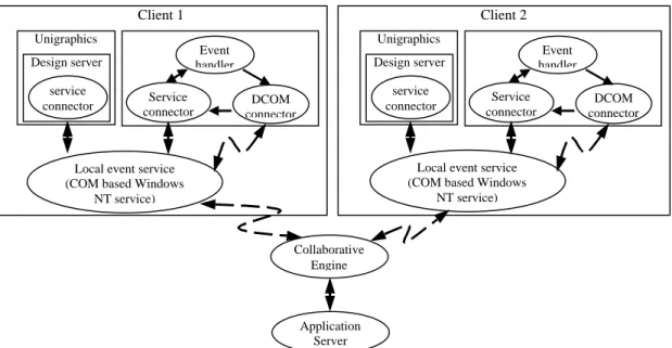
technology was been adopted torealize the concept of distributed computing. COM/DCOM is a native function of Windows NT platform and no third party distributed computing services are needed [10]. Figure 5 shows the framework of the collaborative solid modeling environment for mechanical design. Event handler can be triggered by user actions to send events to Unigraphics and collaborative engine via local event service. For example, if client 1 creates a new feature, event handler in client 1 will send an event to Unigraphics with an event object. Unigraphics creates the feature and updates the model. At the same time, the local event service also sends an event to the collaborative engine. The collaborative engine will further broadcast the event to application server and client 2. The local event service in client 2 will delegate the event to its local Unigraphics. The design server developed based on Unigraphics can automatically replicate the action performed by client 1 based on the information transferred in with this event so that client 2 can see the changes immediately.
5.2 Features Covered
Table 4 shows the features supported by the developed environment. Correspondingly, the XML tags are also worked out to describe the features. Some of XML tags are shown in Table 5. Based on feature description tags, a complete information packet is shown in Figure 6.
5.3 Graphic User Interfaces
Figure 7 shows the graphics user interface for collaborative modeling. On this screen, users can create, modify or delete a feature. Other clients can be aware of these actionscan be aware ofthe actions in real time. On the screen shown in Figure 8, users can log into or off the collaborative engine, and subscribe to eventsthat he/she isinterested.
TABLE 4 FEATURES COVERED No. Feature Name
1 Cylinder 2 Cone 3 Cylindrical hole 4 Conic hole 5 Thread hole 6 Counterbore hole 7 Countersunk hole 8 Counterbore thread hole 9 Countersunk thread hole Designer A Part A Part B Customer Designer B Manufacturer Part A Part B
TABLE 5 FEATURES COVERED
No. Tag Name Remark
1 FeatureID Unique feature ID 2 FeatureName Name of the feature 3 FeatureType Type of the feature 4 Length Length value 5 Width Width value 6 Height Height value 7 Depth Depth value 8 Diameter Diameter value 9 Radius Radius value 10 Roughness Roughness value
11 SideRoughness Roughness value of side surface
12 BottomRoughness Roughness value of bottom surface
13 Accuracy Accuracy of feature
Fig. 7 Screen for modeling
Fig. 8 Screen for remote connection CONCLUSIONS
In this paper, through collaboration scenario and requirements analysis, a collaborative engine has been developed. Meanwhile, An XML-based information transmission approach is also presented. The collaborative engine can facilitate the development of new collaborative <Packet type=”Action”> <Header> <Sender>Chris</Sender> <ID>776600100132634424252563</ID> <Team>134124124234151234523453</Team> <Time>10:10:05<Time> <Date>19-09-2001<Date> <Synchronal>true</Synchronal> </Header> <Command name=”Add”> <Entity> <Feature> <FeatureType>Hole</FeatureType> <FeatureName>Hole 1</FeatureName> <FeatureID>H00013<FeatureID> <Diameter>24</Diameter> <Height>60</Height> <SideRoughness>3.2<SideRoughness> </Feature> <Entity> </Packet>
Fig. 6 Representation of a packet
Fig. 5 Framework of collaborative design environment Collaborative Engine Client 1 Unigraphics Design server service connector
Local event service (COM based Windows
NT service) Service connector DCOM connector Event handler Application Server Client 2 Unigraphics Design server service connector
Local event service (COM based Windows
NT service) Service connector DCOM connector Event handler
applications and integration of legacy applications into a collaborative environment. Through managing user sessions, task sessions and team sessions, the collaborative engine maintains an independent as well as collaborative working space within the collaborative environment for users and teams. The collaborative engine provides some generic functions related to collaboration, such as managing real-time tasking, broadcasting events, managing sessions, and maintaining discussions. A prototype engine has been developed using COM/DCOM technology. The prototype of a 3D solid modeling environment for mechanical design has been developed. It shows that the collaborative engine can facilitate real-time tasking through providing a collaborative environment that has capabilities to manage events, activities, tasks and meetings.
REFERENCES
D. A. Dierolf and K. J. Richter, “Computer-Aided Group Problem Solving for Unified Life Cycle Engineering (ULCE)”, IDA Paper P-2149, 1989
S. Finger and J. R. Dixon, “A Review of Research in Mechanical Engineering Design. Part 1: Descriptive, Prescriptive, and Computer-Based Models of Design Processes”, Research in Engineering Design, No. 1, 1989, 51-67
S. Finger and J. R. Dixon, “A Review of Research in Mechanical Engineering Desing. Part 2: Representations, Analysis, and Design for the Life Cycle”, Research in Engineering Design, No. 1, 1989, 121-137 Gun-dong F. Pahng et al, “WEB-based Collaborative Design Modelling and Decision Support”, ASME Design Engineering Technical Conferences, 1998, Atlanta, Georgia
Bert Bras, Farrokh Mistree et al, Designing Design Processes in Decision-based Concurrent Engineering, SAE Transactions, Journal of Material & Manufacturing, 1991, vol. 100, 451-458
Lu, S. C. Y. Cai et al, “A Methodology for Collaborative Design Process and Conflict Analysis”, CRP Annals, 2000
Uwe Jasnoch, Satish K. Asok, Stenfan Hass, “A Collaborative Environment Based on Distributed Object-Oriented Databases”, 1995 IEEE, 1995, 1080-1383
M. Hardwick and D. Spooner, “An Information infrastructure for a Virtual Manfacturing Enterprise”, Proceedings of Concurrent Engineering: A Global Perspective, McLean, VA, 417-429, 1995
Clive Finkestein et al, Building Corporate Portals with XML, The McGraw-Hill Companies, Inc., 2000
Guy Eddon et al, Inside Distributed COM, Microsoft Press, 1998
Frank E. Redmond III, DCOM Microsoft Distributed Component Object Model, IDG Books Worldwide, Inc.
C. Gilman et al, Integration of Design and Manufacturing in a Virtual Enterprise Using Enterprise rules, Intelligent agents, STEP, and workflow, Architectures, Networks, and Intelligent Systems for Manufacturing Integration, 1997, 160-171
M. Gruninger et al, The Logic of Enterprise Modelling, Modelling and Methodologies for Enterprise Integration
N. Senin., N. Borland, and D. R. Wallace, “Modeling and Evaluation of Product Design Problems in a Distributed Environment”, CD-ROM Proceedings of ASME DETC, Sacramento, CA, 1997
David A. Koonce, “Information Model Level Integration for CIM Systems: A Unified Database Approach to Concurrent Engineering”, http://www.ent.ohiou.edu/~dkoonce/papers/cie.h tml
M. Billinghurst, “Spatial Conferencing using a Wearable Computer”, CSCW 98, Seattle, WA98195, 1998
P. D. Stotts and R. Furuta, “Browsing Parallel Process Networks”, Journal of Parallel and Distributed Computing, No. 1, 1990, 224-235 L. F. Bic, M. Fukuda, and M. B. Dillencourt, “Distributed Computing Using Autonomous Objects”, IEEE Computer, No. 8, 1995, 55-61