READ THESE TERMS AND CONDITIONS CAREFULLY BEFORE USING THIS WEBSITE. https://nrc-publications.canada.ca/eng/copyright
Vous avez des questions? Nous pouvons vous aider. Pour communiquer directement avec un auteur, consultez la première page de la revue dans laquelle son article a été publié afin de trouver ses coordonnées. Si vous n’arrivez pas à les repérer, communiquez avec nous à [email protected].
Questions? Contact the NRC Publications Archive team at
[email protected]. If you wish to email the authors directly, please see the first page of the publication for their contact information.
NRC Publications Archive
Archives des publications du CNRC
This publication could be one of several versions: author’s original, accepted manuscript or the publisher’s version. / La version de cette publication peut être l’une des suivantes : la version prépublication de l’auteur, la version acceptée du manuscrit ou la version de l’éditeur.
Access and use of this website and the material on it are subject to the Terms and Conditions set forth at
A Standard for computer-aided design/drafting (construction)
Strelka, C. S.; Vanier, D. J.
https://publications-cnrc.canada.ca/fra/droits
L’accès à ce site Web et l’utilisation de son contenu sont assujettis aux conditions présentées dans le site LISEZ CES CONDITIONS ATTENTIVEMENT AVANT D’UTILISER CE SITE WEB.
NRC Publications Record / Notice d'Archives des publications de CNRC:
https://nrc-publications.canada.ca/eng/view/object/?id=d9a5606b-7d7c-4fb7-bad9-b1cac0d54884 https://publications-cnrc.canada.ca/fra/voir/objet/?id=d9a5606b-7d7c-4fb7-bad9-b1cac0d54884
Ser
I
N21d National Research Conseil national
no. 1431
1
19
Council Canada de rechercher Canadac. 2 1
' BLDG Institute for lnstitut de
- - - / Research in recherche en
Construction construction
A
Standard for Computer-Aided
Design/Drafting (Construction)
by C.S. Strelka and D.J. Vanier
Appeared in
Proceedings of the 10th Triennial Congress of the International Council for Building Research, Studies and Documentation, (CIB-86) Washington, D.C., September 22-26, 1986
Vol. 1, For the Computer Age, p. 231 -239 (IRC Paper No. 1431)
Reprinted with permission
Price $2.00 NRCC 26794 NRC
-
CISTI I R C L I B R A R YFEB
13
;?sr
B I B L I O T H ~ Q U E I R C CNRC-
iC1sTA Standard for Computer-Aided Design/Drafting (Construction) Charles S. Strelka, Chairman CSA 78.3
Dana J. Vanier, Chairman CSA B78.5 Division of Building Research National Research Council Canada
Ottawa, Ontario KIA OR6, CANADA KEYWORDS
Construction, Buildings, Computer Graphics, Computer-Aided Design, Computer- Aided Design Drafting, Drafting Standards, Drafting Symbology.
ABSTRACT
The recent move to automated technology by the construction industry has created a need for a consensus on symbology and presentation for computer- aided designldrafting before the majority of the community adopts the technology. A standard for computer-aided desigddrafting would greatly
assist the construction industry and the development of software in Canada and in the international community. Canadian Standards Association Committee B78.5 has developed a Canadian standard which applies to the computer-aided preparation and reproduction of construction drawings. In general context, it establishes the detailed recommendations on symbology and drafting techniques for computer-aided design/drafting in the construction industry. This paper introduces the standard, which will be published in summer 1986, and outlines the history of the standard, the requirement for standardization of computer- aided design/drafting, the goals of the standard, and the potential benefits for the construction industry.
Norme en matiere de conception/dessin assist6 par ordinateur (construction) Charles S. Strelka, prdsident ACNOR 78.3
Dana J. Vanier, pr6sident ACNOR B78.5 Division des recherches en blitiment Conseil national de recherches Canada
Ottawa (Ontario) KIA 0R6, CANADA MOTS CLEFS
Construction, batiments, infographie, conception assistee par ordinateur, conception/dessin assist6 par ordinateur, normes de dessin, symbolique du dessin.
Par suite de la recente vague d'informatisation qu'a connue l'industrie de la construction, il est apparu n6cessaire de s'entendre sur la symbolique et la presentation de la conception/dessin assist6 par ordinateur avant que la plupart n'emboftent le pas. L'existence d'une norme en cette matisre
serait tres utile it l'industrie de la construction et favoriserait
grandement le developpement de logiciels au Canada et dans les autres pays. C'est pourquoi le cornit6 B78.5 de 1'Aseociation canadienne de normalisation a Blabore une norme canadienne s'appliquant 3 la rgalisation et 3 la
reproduction de dessins de construction par ordinateur. Cette norme renferme des recommandations dCtaill6es concernant la symbolique et les techniques en matiere de conception/dessin assist6 par ordinateur dans l'industrie de la construction. Ce document prgsente la norme, qui sera publiee
B
1'Btd 1986, puis il en trace un historique, indique pourquoi il importe de normaliser la conception/dessin assist6 par ordinateur, Cnonce les objectifs de la norme et prdcise les avantages que pourrait en retirer l'industrie de la construction.INTRODUCTION
This paper introduces a standard for computer-aided design drafting
(construction) and provides an outline of its development, the requirement for standardization of computer-aided design/drafting, details of the proposed structure of Canadian Standards Association (CSA) Standard B78.5, and benefits of the standard. The standard applies to the computer-aided preparation of construction drawings and, in general context, it establishes detailed recommendations on implementation of drafting techniques and symbology for computer-aided design/drafting in the construction industry.
HISTORY OF CSA B78.5
The origins of CSA B78.5 are found in a sister document, CSA B78.3-Standard on Building Drawings [I]. The CSA was given the mandate by the Standards Council of Canada to prepare the Standard on Building Drawings as one of CSA'3 Tech- nical Drawing Standards series. This was done primarily to assist the
construction industry in the conversion to metric usage in design and on the building site. The committee was established in 1975 and this standard was
released after nation-wide approval in 1977. It was later confirmed as a National Standard, CAN3-B78.3-M77-Building Drawings. Subsequent to this, a commentary on CSA B78.3 was published in 1983 by the Division of Building Research (DBR) [2].
In the early 19801s, it was realized by DBR and CSA that computer technology would play an important role in design/drafting in years to come and a
standards group should develop a consensus on the basic issues before the majority of the community adopted the technology. A meeting of interested parties was held in October 1983 and this ad hoc group was officially
recognized as a CSA Committee in January 1984. The standard was submitted for CSA approval in February 1986. On recommendation by the Canadian delegate to the International Standards Organization (ISO) Technical Committee (TC) 10, Subcommittee (SC) 8, a similar working group has been formed to develop a draft international standard. Delegates from the United Kingdom, Sweden, Norway, Canada, and Finland attended the first meeting in September 1985 and Working Group (WG) 12 is looking closely at the Canadian initiative for direct ion.
CADD PHILOSOPHY
Computer - A&xl Desian/Draftina
The Committee recognized that designidrafting had definite boundaries and the standardization of symbols and presentation would be extremely useful not only for the construction industry, but also for software manufacturers. To
restrict the standard to production drafting would not include the designers in the industry: engineers, architects, and interior designers. The committee agreed that computer-aided design (CAD) was too large a technology for
standardization. Computer-aided design/drafting (construction) was therefore selected as the mandate of the Committee and the standard addresses the
requirements of both the drafter and the designer. Adopt -xE , a Practise
The final product
-
the construction drawing-
must be readable not only by the technical personnel, but also by the site operator and the constructionworkers. This indicated to the committee that it would take some time for the entire construction industry to adopt CADD techniques or for the technology to reach the various construction disciplines: therefore conventional drafting symbols and methods had to be retained. This standard adopts conventions for symbology and presentation currently accepted in construction practice.
Many Committee discussions focused on the merits of automation systems for the construction industry; the majority of existing CADD systems provide only minimal production-time decreases and productivity increases and these systems
relate more to the mechanical parts and printed circuit board design than to construction drafting practice. In addition, the low popularity of CADD within the construction fraternity in the early 80's indicated that the structure of the information was not suited for design/drafting in the
building industry. Committee members decided that different directions had to be investigated to meet the requirements of the construction industry and still have the standard amenable to automation. The standard provides a
structure reflecting current thinking for computer graphics that can be met by existing CADD systems.
nce of Info
-The major difference between CADD and manual practice is the data handling capability of automated systems. All CADD systems employ an internal data structure, either sequential, hierarchic, or relational, to organize the
graphical data. However, in most conventional CADD systems, many capabilities of the computer or data structures are not being optimized by practitioners, or worse, by the software developers. This standard is designed to encourage the use of a data structure relating to the structure of construction infor- mation and is written to optimize CADD systems without affecting the final drafting product. This data structure is described at length later in this document.
txed and P r e s e n t a m
The computer draws quickly and the information can be easily modified; these are saving graces of CADD technology. Its drawbacks are that some operations,
such as toning, hatch, or poch8, are more easily accomplished and more cost-
effective using manually-placed tone sheets. In addition, data retrieval and search strategy using conventional sequential files greatly limits design alterations or "what if?" scenarios and therefore restricts designers.
Alternate methods had to be investigated to find a solution that would use the speed and presentation possibilities of the CADD equipment and make it more cost-effective than manual practice. The solution was found in the structure
of existing computer graphic standards in related fields. CSA B78.5
encourages a data structure closely resembling that of construction information.
B i s s e m ~ of Good Draftina Practice
The information explosion made possible by advanced computer technology has both helpful and debilitating effects. It disseminates information rapidly; the library symbols developed in one province or state are passed to other locations when CADD software is sold. Unfortunately, the symbol libraries may be of poor quality, incongistent structure, or just plain wrong, because
standards developed by CADD vendors are normally created by junior staff
see standards organizations developing the standard symbology, and making this available to CADD vendors: the standard is thus made available to a wide
audience.
EXISTING INTERNATIONAL STANDARDS AND PRACTICES IN COMPUTER GRAPHICS
CSA B78.5 was greatly influenced by existing standards in related fields and salient points from these standards are reflected in the structure of the standard for computer-aided desigddrafting. ..These standards are Graphical Kernel System (GKS) [31 for computer graphic protocols and the Initial Graphics Exchange Specification (IGES) [4] for the exchange of CADD data. GKS is a protocol for ensuring that graphics software running on one input or output device should run equally well on another. It was adopted as IS0 7942 and is supported by a large number of computer graphics firms. One important feature of GKS is the use of attribute data, i.e. additional information tagged to graphical data. This permits descriptive information, whether alphanumeric or graphical, to be added to specific graphical data. This concept is essential for CADD in the construction industry: the structure of building information has similar requirements and the ability to tag
additional information to the graphical representation is imperative. IGES is a protocol for transferring CADD data from one "turnkey" system to another. The general principle of the specification is for all CADD vendors to send their data to a well-defined file format. Once in this file format, the information can be transferred to any other CADD system. This saves CADD vendors from having to develop a translator to and from all of their
competitors' systems. It is still in a developmental stage, is heavily
graphics-based and numerous levels of compatability for data transfer already exist. In addition to being necessary in the CADD industry for data transfer,
IGES structures reflect the requirements of the structure of construction industry information. This protocol therefore had significant impact on the development of the standard. The CSA B78.5 standard complements IGES and thereby facilitates the communication between different machines and systems. In addition to the computer graphics standards, a number of manual practices
influenced the CADD standard. These include CSA 878.2, Technical Drawings
-
General Principles [5], IS0 documents relating to graphical presentation for construction drawings, the ASHRAE Handbook [61, and the Handbook of the Canadian Institute of Steel Construction t71.
PROPOSED DATA STRUCTURE FOR CADD INFORMATION
The structure of CADD information encouraged in the standard can be imple- mented with all CADD systems. It provides the framework for CADD information and will assist in the data entry, data manipulation, and data storage and retrieval at different stages of design and building operation. This pertains to project-specific or library-specific information. Filing and drawing
management in the drafting office are beyond the scope of the standard.
Data structure means the arrangement of information in a logical format so as to be easily accessed and modified by the computer. This can be the internal structure the computer uses to arrange the data or the external structure developed by the CADD user to arrange the building information. The standard encourages the use of an external data structure that reflects the function of
t h e b u i l d i n g component. F o r example, a l l t h e i n f o r m a t i o n f o r t h e e l e c t r i c a l system s h o u l d be s t r u c t u r e d t o r e p r e s e n t t h e e l e c t r i c a l network d e s i g n . To d a t e , t h e o n l y CADD e x t e r n a l d a t a s t r u c t u r e h a s been l a y e r i n g . L a y e r i n g was e s s e n t i a l i n CADD s y s t e m s of t h e 7 0 ' 3 , b u t it r e f l e c t s t e c h n o l o g y d e v e l o p e d f o r m e c h a n i c a l p a r t s and p r i n t e d c i r c u i t b o a r d d e s i g n and n o t t h e d i v e r s e needs of t h e c o n s t r u c t i o n i n d u s t r y . Although it p a r a l l e l e d p i n - r e g i s t e r e d d r a f t i n g t e c h n i q u e s , it o n l y o p t i m i z e d d a t a i n p u t f o r CADD i n f o r m a t i o n h a n d l i n g . A s w i t h word-processing, t h e r e a l v a l u e i n a u t o m a t i o n i s i n m o d i f i c a t i o n and r e u s e of i n f o r m a t i o n , and t h i s i s e s s e n t i a l i n t h e b u i l d i n g i n d u s t r y . C o n v e n t i o n a l l a y e r i n g u s e s o n l y one l e v e l i n t h e o u t p u t p r e s e n t a t i o n s t r u c t u r e . The u s e r c a n t u r n on o r t u r n o f f one l a y e r of i n f o r m a t i o n on t h e s c r e e n o r t h e o u t p u t d e v i c e a t a t i m e , t h e r e b y r e s t r i c t i n g t h e u s e of t h e i n f o r m a t i o n . A d d i t i o n a l work i s r e q u i r e d by t h e d r a f t e r o r d e s i g n e r i f t h e i n f o r m a t i o n i s r e q u i r e d i n a d i f f e r e n t form.
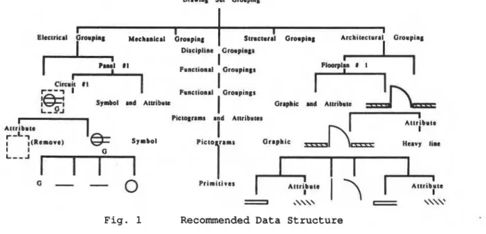
To augment l a y e r i n g , a m u l t i - t i e r e d tree s t r u c t u r e i s s u g g e s t e d i n CSA B78:S.
I t m i r r o r s t h e s t r u c t u r e of c o n s t r u c t i o n i n f o r m a t i o n , f o l l o w s t h e r a t i o n a l e of t h e d e s i g n p r o c e s s , a n d c a n b e e a s i l y u n d e r s t o o d by t h e m a j o r i t y of t h e p e r - s o n n e l i n v o l v e d . An example of t h i s form of d a t a s t r u c t u r e i s s e e n i n F i g . 1. P r i m i t i v e s a r e t h e l o w e s t l e v e l of a g r a p h i c o r an a l p h a n u m e r i c e n t i t y . They may b e l i n e , a r c , s p l i n e , t e x t , f i l l , polygon, o r a n y o b j e c t t h a t c a n n o t b e f u r t h e r s u b d i v i d e d by t h e u s e r . Every p r i m i t i v e c a n p o s s e s s a number of a t t r i b u t e s . T h e u s e of p i c t o r i a l r e p r e s e n t a t i o n i s e n c o u r a g e d where no c o n f u s i o n a r i s e s w i t h t h e s e l e c t i o n of t h e p i c t o g r a m . I t must a l s o b e p o s s i b l e t o b r e a k down t h e s e components t o f a c i l i t a t e t h e m o d i f i c a t i o n of symbols and t o i n c r e a s e t h e number of a v a i l a b l e symbols. To d i f f e r e n t i a t e t h e v a r i o u s t y p e s of
p i c t o g r a m s , two new t e r m s have been d e v e l o p e d : symbols and g r a p h i c s . Symbols
Symbols a r e p i c t o g r a m s n o t drawn t o s c a l e . They c a n p o s s e s s a g r a p h i c a l r e f e r e n c e which d e n o t e s t h e l o c a t i o n of t h e symbol on t h e d r a w i n g o r
s c h e m a t i c , a g r a p h i c a l r e f e r e n c e p o i n t which d e n o t e s t h e o r i g i n o r "handle" f o r r o t a t i o n , s c a l e and t r a n s l a t i o n (move), and a r e l a t i o n s h i p t o a h i g h e r f u n c t i o n a l g r o u p i n g which d e n o t e s t h e s y m b o l ' s " p a r e n t " , a n d c a n c o n s i s t of a number of p r i m i t i v e s , g r a p h i c s , o r o t h e r symbols. Symbols c a n p o s s e s s
a t t r i b u t e s and t h e i r components c a n a l s o c o n t a i n a t t r i b u t e s (see F i g . 2 ) . G r a p h i c s
A g r a p h i c i s a d i m e n s i o n a l l y - a c c u r a t e p i c t o g r a m . I t may b e a s i m p l i f i e d
r e p r e s e n t a t i o n of a b u i l d i n g component, b u t i t i s a c c u r a t e w i t h r e s p e c t t o t h e p r i n c i p a l d i m e n s i o n s . G r a p h i c s c a n p o s s e s s a g r a p h i c a l l o c a t i o n , a g r a p h i c a l r e f e r e n c e p o i n t , and a r e l a t i o n s h i p t o a h i g h e r f u n c t i o n a l g r o u p i n g , and can c o n s i s t of a number of p r i m i t i v e s , symbols, o r o t h e r g r a p h i c s . G r a p h i c s c a n p o s s e s s a t t r i b u t e s and t h e i r components can a l s o c o n t a i n a t t r i b u t e s
The term grouping is used to denote a function-dependant collection of
symbols, graphics, primitives or other groupings. A grouping may include
attributes that are related to the entire group or may be specific to
individual components of the grouping. Groupings can be as large as a drawing set or as small as a number of primitives.
Conventional CADD methods greatly increase the amount of data handled in the standard office owing to the facility of creating "variations on a theme". This, however, creates considerable redundant information. In the most simple
case, there is no need to create 20 or 30 different symbols in a CADD library
based on permutation of a standard I-Beam; one will suffice, but that symbol will possess graphical attributes of height, flange width, and thickness, and numeric attributes of weight per metre, supplier, etc. These may be
alphanumerics (i.e. text, letters) that distinguish between types of nearly identical components, as in the case of Fig. 2, or graphical features
indicating a different usage, as in the case of Fig. 3; even colours can be
considered attributes. The use of attributes will assist in the production of bilingual drawings; French, English or both may be shown when required.
The attributes form part of the primitive, pictogram, or grouping and it should be possible to alter the attributes of any component either locally
(for a specific component), globally (for a number of discrete components), or temporarily ("non-permanent")
.
In addition, attributes associated with lower level components (primitives, pictograms, etc.) must override attributes of higher level components (their parents, grouping, discipline drawings.). Yorld Coordinate SvstemgCADD systems store information in "on-site" measurements and use the computer
to calculate the representation at various scales. If a building is 50 metres
long, it is entered on the CADD system as 50 metres. When plotted or viewed on the screen it can be shown in any scale required. This creates some problems with standard symbols because the drawing in computer storage is always full size, therefore the symbols must be able to display the proper information at all scales.
ADDITIONAL BENEFITS OF A CADD STANDARD IN THE BUILDING INDUSTRY
There are numerous benefits for standardization in this rapidly-evolving technology. Some of the more obvious are listed below:
-The standard promotes the use of the speed and intelligence of the CADD systems in many areas, as they relate to building design/drafting, to obtain a long-term high productivity for CADD users.
-
The standard reflects current thinking in computer graphics, implementingfaster, more effective techniques for automated drafting and thereby extending the life of the standard.
-The standard acts as a teaching tool for novice designers and drafters by providing standard symbols, line thicknesses, lettering styles,
-The standard assists the sale of CADD systems by providing a full set of drafting tools to the user: the vendor has a machine to draw lines, but CSA provides him (and thereby practitioners) with the templates, font styles, presentation formats, symbols, etc.
This paper is a contribution of the Division of Building Research, National Research Council of Canada.
REFERENCES
1. CAN B78.3
-
M77-
Building Drawings, ISSN 0317-5669 (Canadian Standards Association, Rexdale, Ontario, 1977).
2. C.S. Strelka and D. Westwood, "Commentary on CAN B78.3
-
M77-
Building Drawings", Building Practice Note 43 (Division of Building Research, National Research Council Canada, Ottawa, 1983).3. Graphical Kernel System (GKS)
-
Functional Description, IS0 7942 (Standards Council of Canada, Mississauga, Ontario, 1985).4. B. Smith, Initial Graphics Exchange Specification (IGES) Version 2.0 (National ~echnical Information Service, Springfield, VA, 1983).
5. CSA B78.2
-
M83, Technical Drawing-
General Principles (Canadian Standards Association, Rexdale, Ontario, 1983).6. ASHRAE Handbook, 1985 Fundamentals, Chapter 36, Abbreviations and Symbols (American Society of Heating, Refrigeration and Air Conditioning Engineers, Atlanta, 1985).
7. Manual of Steel Construction (Canadian Institute of Steel Construction, Toronto, 1970).
1 1 1
Elactrlelf G M P ~ W Mechrnicrl Grouping Structrr!l Grouping Discbpllna
,
Gmnplm#~Phnctiomml Oroupir#s
I
Fsnetioall Orompings
S m and A t v l k u
I
OrspbiE d AnrlbruI
Mlgnm mad AtUlbrwrI
Actribmra
r - L i
I I t l a m o r a ) S r a b o l Orrpbie
-
Heavy finoI I
0 -
-F i g . 1 Recommended Data S t r u c t u r e
G
-
Grounded Circuit T v ~ e S-100b DoorT h i s paper i s being d i s t r i b u t e d i n r e p r i n t form by t h e I n s t i t u t e f o r Research i n C o n s t r u c t i o n . A l i s t of b u i l d i n g p r a c t i c e and r e s e a r c h p u b l i c a t i o n s a v a i l a b l e from t h e I n s t i t u t e may be o b t a i n e d by w r i t i n g t o t h e ~ u b l i c a t i b n s S e c t i o n , I n s t i t u t e f o r Research i n C o n s t r u c t i o n , N a t i o n a l Research C o u n c i l of C a n a d a , O t t a w a , O n t a r i o , K1A 0R6. Ce document e s t d i s t r i b u Q s o u s forme de tirb-A-part p a r 1 ' I n s t i t u t de r e c h e r c h e e n c o n s t r u c t i o n . On peut o b t e n i t une l i s t e d e s p u b l i c a t i o n s de 1 ' I n s t i t u t p o r t a n t s u r les t e c h n i q u e s ou l e s r e c h e r c h e s e n m a t i s r e d e b t t i m e n t e n Q c r i v a n t 3 l a S e c t i o n d e s p u b l i c a t i o n s , I n s t i t u t de r e c h e r c h e e n c o n s t r u c t i o n , C o n s e i l n a t i o n a l d e r e c h e r c h e s du Canada, Ottawa ( O n t a r i o ) , KIA OR6.