EcoGRAFI
2nd International Conference on Bio-based Building Materials & 1st Conference on ECOlogical valorisation of GRAnular and FIbrous materials
June 21th - 23th 2017
Clermont-Ferrand, France
PRELIMINARY INVESTIGATION ON USE OF SEWAGE SLUDGE ASH AS PARTLY
CEMENT REPLACEMENT IN LIGHTWEIGHT AGGREGATE CONCRETE
Lisbeth M. Ottosen*, Randi J. Olsen, Esben Ø. Hansen
Technical University of Denmark, Department of Civil Engineering, DK-2800 Kgs. Lyngby, Denmark *Corresponding author; e-mail: LO@byg.dtu.dk
Abstract
This work is a preliminary investigation on major properties for lightweight aggregate (LWA) concrete where sewage sludge ash (SSA) partly replaces the cement. To use SSA in LWA
concrete production could lower the CO2 footprint (due to use of less cement) and maybe also
give better thermal insulating properties, as the SSA particles are porous and might result in a more porous LWA concrete, the thermal conductivity is however not investigated in this preliminary work. Blocks of LWA concrete were cast. The replacement percentage of cement with SSA was varied: 0, 15, 20, 25, 30, 35 or 45%. From each block, test specimens were drilled (75 mm in both diameter and height). Porosity and compressive strength were measured. It was found that up to 30% SSA did not reduce the compressive strength significantly compared to the reference. These replacement percentages without strength loss are high compared to mortar samples in a previous investigation with SSA from the same incineration plant. The compressive strength of the laboratory produced reference LWA concrete was 1.75 MPa, which was lower than an industrial produced LWA concrete (3 MPa) with the same aggregate, fly ash and cement mass ratio. The mass of water to obtain a LWA concrete mix ideal for casting increased with
increasing SSA mass. This due to the porosity and irregular shape of the relatively coarse (d50
95 µm) SSA particles. The water demand for mortar with this SSA replacing 20% cement was increased by 16% compared to the reference without SSA. Thus, the increased need for water in the LWA concrete mixture was as expected. The porosity of the LWA concretes with SSA was higher than the reference, which partly might be due to the high porosity of the SSA particles, revealing that the thermal conductivity was lower. Thus all together the results from this investigation are encouraging in order to continue the research topic.
Keywords:
Ligthweight concrete, wood ash, sewage sludge ash, mechanical properties
1 INTRODUCTION
Sewage sludge incineration is a well proven technology with hundreds of plants worldwide [Werther & Ogada, 1999] and inevitably from the incineration is the production of sewage sludge ash (SSA). Today SSA is most often disposed of as a waste product, but quite extensive research focus on changing this status
to resource in construction materials. This
development fully supports the European Union's target to reduce final waste disposal in 2050 by 50% compared with 2000.
There are several options for reuse of SSA in the construction industry, which have shown interesting potential. The most important are: (I) component in the mixture of raw materials for cement production, (II) active additive for cementitious inorganic binders in concrete and mortar, (III) bearing component of the raw material in the manufacture of building ceramics (bricks, ceramic tiles), (IV) component of the synthesis of lightweight materials, (V) substitute for sand and/or cement in cement stabilized bases, (VI) and sub-bases
and embankments in road constructions [Smol et al., 2015].
Whether SSA is a pozzolanic material it must be said, that the results found in literature on the use in normal weight concrete are ambiguous. This can be due to the fact, that some SSAs are pozzolanic while others not and it may also relate to the use of different methods for determination of the pozzolanity [Ottosen et al 2013a].
It should be noticed, that SSA generally has a high phosphorous content, see e.g. [Cyr et al. 2007] and as phosphorous is a scarce resource, quite extensive research is conducted on developing techniques for recovery of this element [Donatello & Cheeseman, 2013]. After phosphorous recovery, sustainable use of the remaining ash should be found. However, as the phosphorous recovery techniques are still in the state of research and development, the characteristics of this ash residue is not known. Thus, knowledge is built from the SSA as produced directly from the incineration, and later this knowledge must be used in
assessing the possible use for the ash after phosphorous extraction, which will have other characteristics than the original ash.
The present study is an initial investigation on the use of SSA as cement replacement in lightweight aggregate (LWA) concrete. Focus is on the influence of the replacement on the compressive strength. A LWA concrete recipe used industrially is used as base for the present investigation. From this basic recipe, different percentages of cement are replaced with SSA to investigate how large a percentage of the cement can be replaced with SSA before the overall strength is comparable to the limit strength.
The thermal resistance of LWA concrete is up to six times that of normal weight concrete [Chandra & Berntsson, 2002]. The thermal conductivity of lightweight aggregate concrete is related to its pore structure or air-void system. With air as the insulating material, concrete of a higher porosity and a lower density will have a lower thermal conductivity. The air-pore system in the LWAC depends upon the binder system and the chemical admixtures used. With the addition of silica fume and fly ash, thermal conductivity is decreased [Chandra & Berntsson, 2002]. SSA particles generally have a porous structure [Cyr et al. 2007] and an idea of using SSA as cement replacement is that this porosity of the SSA adds to the overall porosity and that these SSA may be used in the binder system without decreasing the thermal conductivity as fly ash or silica fume. In case this can be verified, the use of SSA in LWA concrete has
multiple benefits as a lower CO2 footprint from a lower
cement use and a better product in terms of insulating property compared to the case where coal fly ash is used. This paper though, is the initial assessment of the possibility, which focus on the mechanical properties and porosity of LWA concrete with SSA.
2 MATERIALS ANS METHODS
2.1 Ashes and characterization
The SSA tested as cement replacement was from
Avedøre Spildevandscenter, Denmark, where
wastewater sludge from about 330,000 PE is
incinerated. During wastewater treatment,
phosphorous was precipitated with Fe. The ash from electrofilters was mixed with flue gas neutralization products (lime) from bag filters.
Ash pH and conductivity was measured by suspending 10.0 g ash in 25 ml distilled water. After 1 hour agitation, pH was measured directly in the suspension with a Radiometer pH electrode. Loss on ignition (LoI) was found after 30 minutes at 550ºC. Water content was measured as weight loss after 24 hours at 105ºC (calculated as weight loss over the weight of the wet sample). Three replicates of each of these analyses were made.
Solubility in water was evaluated: 50.0 g ash suspended in 500 ml distilled water and agitated for 1 min. After setting, the water was decanted. New 500 ml distilled water added. This was repeated so the ash was washed three times. Finally, the suspension was filtered and the ash dried at 105°C and weighed. Concentrations of P, Cu, Pb, Zn and Cd were measured in all samples with a Varian 720-ES ICP-OES (Inductively Coupled Plasma - Optical Emission Spectrometry). SSA samples were pre-treated in accordance to Danish Standard DS259: 1.0 g ash and
20.0 ml (1:1) HNO3 was heated at 200 kPa (120 C) for 30 minutes and filtered through a 0.45 µm filter prior to the analysis by ICP-OES.
The particle size distribution was measured with a laser diffractometer.
2.2 Water requirement of SSA
The water requirement resulting from the SSA particles was determined from flow values after DS/EN 450-1 (except that this standard valid for coal fly ash and here used for SSA). The flow values were evaluated for mortar samples with varying cement replacement: a reference without SSA and mortars with 10, 20, and 30% cement replaced with SSA. The water requirement (W) was based on the mass (M) of water needed to give a flow value of ± 10 mm from that of the reference. W is calculated as W = (M/225)*100, where the 225 is the weight of water used in the reference mix in [g].
2.3 Lightweight aggregates
The lightweight aggregates (LWA) used in this study were supplied by Webers Saint Gobain, Denmark, and they are known as Leca. Three different fractions of LWA were used: 0-2 mm, 2-4 mm and 4-10 mm. Particle density of the LWAs were determined after DS/EN 1097-6, (Annex C, determination of particle
density and water absorption of lightweight
aggregates) where pycnometers are used. Double determinations were made. The apparent particle
density (ρLa) was calculated as the oven dried mass of
an aggregate sample divided with the volume it occupies in water including closed pores but excluding open pores.
2.4 Recipe and casting
The aggregate weight and cement weight ratios in the used basis recipe for LWA concrete (3 MPa), was supplied by Leca A/S. The use of water to this mixture and if admixtures are used in the industrial process is not known. No admixtures were used in the laboratory procedure.
Ash and LWA were oven dried at 105°C before casting. The ingredients were mixed in a standard concrete mixer. First LWA (0-2 mm) were mixed with water (6.4 kg) for few minutes. LWA (2-4 mm) were added followed by LWA (4-10). The LWAs were left to absorb water for 1 hour before cement, coal fly ash and SSA or WA were added. When the binders were added, time zero was noted. In mixes with SSA, additional water was needed (table 1), and it was added after the binders. The rule of thumb for testing saying that when it is possible to form a ball (as forming a snowball) the mixture was ready for casting. Every LWA concrete mix contained:
• LWA 0-2 mm (15020000_EN 13055-1) 9.48 liter • LWA 2-4 mm (16012000_EN 13055-1) 3.84 liter • LWA 4-10 mm (15118500_EN 13055-1) 21.78 liter • Coal fly ash 1.15 kg (from Nordjyllandsværket,
Denmark)
The mass of SSA, Rapid Cement (CEM I 52.5 N (LA)) and water differed in the different mixes, see table 1. When the mix was ready, a block was cast in a block machine, which. allowed simultaneous decreasing the size of the mould (the lid is the movable part) and vibration.
Table 1: SSA, cement and water in the different mixes SSA (kg) Rapid cement (kg) Water (kg) Ref 0 2.82 6.40 SSA-10 0.28 2.54 6.46 SSA-15 0.42 2.40 6.55 SSA-20 0.56 2.25 6.70 SSA-25 0.70 2.11 6.86 SSA-30 0.85 1.97 6.95 SSA-35 0.99 1.83 7.43 SSA-40 1.27 1.55 7.58
The blocks casted had an untraditional shape (figure 1) as the block machine was designed for another specific purpose. Blocks made industrially are compacted 15% from the original mould size. Such high compaction was not possible for the used block machine. The compaction here was obtained by gradually loading to a pressure of 300 kg under vibration during 1-2 minutes.
Figure 1: a new-cast LWA concrete block. After casting, the block was wrapped in plastic and left for 24 hours. The block was unwrapped and cured in a room where the temperature was between 23 and 27°C and RH between 35 and 65% over the approximately 1.5 month the blocks were cast. The LWA concrete blocks were left to cure 28 days. 2.5 Drilling and cutting test specimens
According to DS/EN 1354 the test specimens must be cubes or cylinders with a length equal to the diameter and not deviating from this with more than 5%. For test specimens with a diameter of 70 mm or more, a test set must consist of at least three specimens.
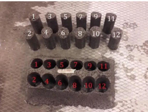
Cylindrical test specimens with the diameter of 74 mm were drilled from the LWA concrete block (see figure 2). The 12 cores were cut into 24 test specimens (or less in case the cylinders were damaged at edges). The LWA concrete blocks SSA-35 and SSA-40 were too weak for drilling of samples. Drilling of SSA-35 only resulted in 4 test specimens, and thus it was decided to cut cubic test specimens from the SSA-40 LWA concrete block (also here only 4 test specimens could be made, as the rest of the block was too weak).
Figure 2: Test specimens drilled from the LWA concrete block.
A commercial LWA concrete block from Webers Saint Gobain was included in the testing program for
comparison (the block is named LWABlock in this
investigation). Identification code for the block: (1)1604xxx_EN 13055-2 (Leca 10-20). The recipe, which was used as base for the LWA concretes cast in the present work, originated from the fabrication of these blocks. Cores were drilled from the commercial block with the same drill as used for the blocks with SSA. All cylinders had cut surfaces also at the ends in order to distribute the load uniformly during compressive strength tests.
2.6 Lightweight aggregate concrete testing Compression tests were performed according to DS/EN 1354. An Instron 5500R compression machine was used, and the displacement applied was 0.1 mm/min. Fibre boards were used between the loadbearing surfaces of the LWA concrete test specimen and the plates of the test machine. For the SSA10, SSA15 and SSA20 the compressive strength were measured on 10 specimens. With higher cement replacements, the drilling of cores resulted in fewer specimens, as the blocks were somewhat fragile. The compressive strength was measured on 6 specimens for SSA25, 8 for SSA30, and 4 for each of SSA35 and SSA45.
After the compressive strength test, at least 80% of the test specimen mass was dried at 105°C until constant mass (no weight loss measured over 24 hours on a scale with two decimals), which took about 3 days. By this the water content at the time of the compression test was found.
The porosity of the different lightweight aggregate
concretes (LWABlock, Ref and with SSA) were
measured by weighing the dry specimens (105°C)
(mdry), vacuum saturated specimens under water (mw)
and over water (ms).
3 RESULTS AND DISCUSSION
3.1 Characteristics of the SSA
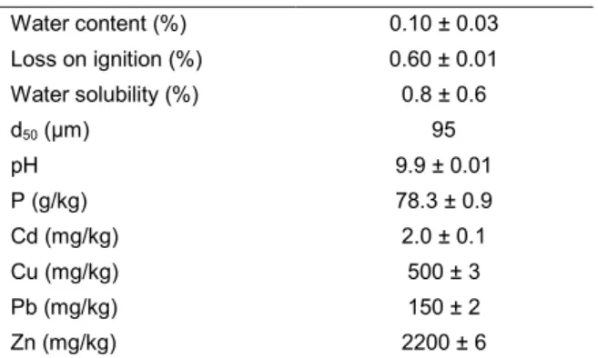
Some characteristics of the SSA used in this investigation are found in table 2.
The heavy metal concentrations reported in literature in different SSAs were collected in [Cyr et al 2007): 200-5400 mg Cu/kg; 1080-10,000 mg Zn/kg, 93-2060 mg Pb/kg and 4-94 mg Cd/kg. The heavy metal concentrations in the present SSA are though in the lower end or even below the concentrations reported for other SSAs. The P content of 7.8% is in slightly less
than previously reported for SSA from this plant (10%) and (12%) [Ebbers et al. 2015], but within the range
reported for other similar SSAs (3.9 – 9.3% P) [Ebbers
et al. 2015]. The waster solubility of the sample was 0.8% with a standard deviation of 0.6%. The high standard deviation compared to the average is a combination of actual differences and an unceartanty from the used method at such low solubility. Ottosen et
al [2013b] gives a more comprehensive
characterization for an SSA sample from the same plant. In our lab it has experimentally been seen by working with different batches of SSA from this plant that the variation in the major characteristics is little over time.
Table 2: Characteristics of the SSA Water content (%) 0.10 ± 0.03 Loss on ignition (%) 0.60 ± 0.01 Water solubility (%) 0.8 ± 0.6 d50 (µm) 95 pH 9.9 ± 0.01 P (g/kg) 78.3 ± 0.9 Cd (mg/kg) 2.0 ± 0.1 Cu (mg/kg) 500 ± 3 Pb (mg/kg) 150 ± 2 Zn (mg/kg) 2200 ± 6
However, between different incineration plants, SSA characteristics vary significantly, and this fact needs to be taken into account, when discussing the options for the use in the construction industry. This means, that characteristics for the SSA needs to be provided together with the tests outlining the possibility for a specific application in construction materials.The characteristics of SSA depends on the socio-economic nature of the catchment area, type of sludge
incinerated and sludge pretreatment process
[Donatello and Cheeseman, 2013]. For example, [Ottosen et al 2013] showed that the characteristics differed significantly between SSA originating from incineration of sewage sludge where P was precipitated with Al or Fe. The general characteristics of SSA reported in the literature was compiled by [Cyr et al, 2007] and the major elements in SSA are Si, Al, Ca, Fe and P. Crystalline forms of these elements are
invariably quartz (SiO2), whitlockite (Ca3(PO4)2) and
hematite (Fe2O3). The amorphous glassy phase
content vary considerably between different SSA samples.
3.2 Water requirement of SSA
In [Cyr et al., 2007] it was concluded on basis of a literature review and own experimental research that all SSAs were composed of irregular particles having a porous structure and that this particle shapes, leads to a high water requirement. The same is seen for the SSA from the plant of the present investigation [Ottosen et al 2013a]
The water requirement (W) for mortar with the SSA in the present study at different replacements (figure 3) shows linearity between the amount of SSA and the
water requirement. The SSA experimentally
investigated in [Cyr et al. 2007] had a +17% higher water demand than the reference at 25% cement replacement and the SSA of the present investigation is at the same level. However, this is not the level of all SSAs also shown in [Cyr et al, 2007] as the range
compiled in literature for 20% replacement was between +14% and +40% water.
Thus, more water is needed than given from the base recipe when SSA replaces cement. The relation between SSA replacement and water requirement cover more than just a mass of water/ash relation, see figure 4, where the mass of SSA vs. extra amount of water is shown. The need for water is increased due to the irregular shape of the ash particles as well.
Figure 3: Water requirement at different cement replacement percentages with SSA
Figure 4: Additional water vs. SSA 3.3 Density of LWA
The apparent particle density (ρLa) of the used LWAs
were: (0-2 mm) 1130 kg/m3, (2-4 mm) 760 kg/m3 and
(4-10 mm) 650 kg/m3. The general density of
lightweight aggregates of expanded clays and slag is
320-960 kg/m3 [Chandra & Berntsson, 2002], and the
two coarse aggregate types falls well within this range. However, the finest of the LWAs (0-2 mm) differed significantly from the larger in a higher apparent particle density. SEM images (not shown) revealed that the finest fraction was produced from crushing larger particles, as the small LWAs had irregular shapes and not the relatively smooth, rounded surface as seen for the larger LWAs. The crushing may have happened mainly through the larger pores of the originally large LWAs thus decreasing the overall porosity.
3.4 Mixing water
The role of thumb of being able to make a “snowball” when adjusting the amount of mixing water during the mixing procedure might seem quite instable. However, the actual result (figure 5) shows a linear relation between the mixing water and the cement replacement with SSA (at levels up to 30%). At replacements higher than 30%, the demand for mixing water increases fast. Actually these replacements coincides with the replacement, where drilling of the samples was difficult
R² = 0.9997 0 20 40 60 80 100 120 140 0 10 20 30 40 W ate r r e q u ire n me n t (W ) Cement replacement (%) y = 0.577x - 19.427 R² = 0.9997 0 10 20 30 40 50 60 70 0 50 100 150 Ad d iti o n al w at e r (g) SSA (g)
due to the LWA concrete matrix not being strong enough.
Figure 5: The dependency of mixing water mass in LWA recipe on the cement replacement with SSA 3.5 Porosity and density of LWA concrete
Specimens
The porosity of the commercial LWA concrete and the specimens casted in the present investigation (10-30% cement replacement) is shown in figure 6. The porosities of the LWA concrete with 30 and 40% cement replacement were not measured due to a very limited amount of specimens, which could be produced from these blocks. The few specimens (four) with these high replacements were used in compressive strength tests.
Figure 6: porosity of LWA specimens. Error bars show maximum and minimum values measured. Apart from the density of the aggregates, the density of the LWA concrete also depends upon the grading of
the aggregates, their moisture content, mix
proportions, cement content, water-to-binder ratio, chemical and mineral admixtures, etc. Besides the material, it also depends upon the method of compaction, curing conditions, etc. [Chandra & Berntsson, 2002]. As the porosity and the density are interrelated, the same factors influences the porosity. The porosity was highest for the commercial LWA concrete and lowest for the reference. The difference is mainly due to the production, where the vibration and compression is better optimized in the industrial process than in the lab process.
The LWA concretes with SSA all had a porosity between the commercial block and the reference block. The porosity is not significantly influenced by the percentage of the cement replacement, so in general it seems as if the porosity is not dependent on the mass of SSA. It is likely, that the relatively coarse particle
size of the SSA (d50 is 95 µm, table 2) influences the
overall particle gradation so the result is a LWA with higher porosity than the reference. At the same time, the porosity of the SSA particles themselves, may also add to the higher porosity, though if this was the only effect, a clear dependency on the mass of SSA and the porosity could be expected.
3.6 Compressive strength
The compressive strength of two commercial LWABlocks
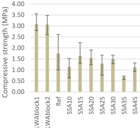
and the blocks casted in the current investigation are shown in figure 4 (average value, maximum and minimum values).
First noticed is that the reference LWA concrete casted in this investigation is less than that of the commercial block. The compressive strength of the commercial LWA concrete was around 3 MPa, which is in consistency with the stated by the producer.
The compressive strength of the reference was in average only 1,75 MPa, which is much less than the commercial LWA blocks. This even though the porosity of the ref is lower (fig.6). The differences is to be found the lab procedure for the casting compared to the industrial process. The compressive strength of the blocks with SSA must be compared to that of the ref, but the higher porosity of the LWA concrete with SSA might decrease the compressive strength more than what would have been seen than if the only parameter varying was the SSA addition.
Figure 7: Compressive strength of LWA specimens. Error bars show maximum and minimum values
measured.
A dominating parameter determining the strength of normal-weight concrete is the water/cement ratio or water/binder ratio. In LWA concrete far from all mixing water is available for hydration, as it is filling the pores of the LWAs. On the other hand, this water can be released during curing and thus over time be available for the hydration (LWAs are suggested as internal water reservoir during curing of high strength concrete due to this property, see e.g. [Akcay & Tasdemir, 2010]). Thus, knowing the exact amount of water available for the hydration process over time cannot be stated on basis of a simple calculation.
The water content of the LWA concrete specimens at the time of the compressive strength test was measured and shown in figure 8. It is seen that there are large variations in the water content of the LWA concrete after 28 days of curing (the time for the compressive strength tests), and this must be related to the environmental conditions during the curing period. The water content of the LWA concrete was very high at the time of casting and during the curing,
R² = 0.9898 0 50 100 150 200 0 10 20 30 40 50 Mi xi n g w ate r (g)
Cement replaced with SSA (%)
0 10 20 30 40 50 60 70 LW A b lo ck Ref SS A 10 SS A 15 SS A 20 SS A 25 SS A 30 Po ro si ty (% ) 0.00 0.50 1.00 1.50 2.00 2.50 3.00 3.50 4.00 LW A b lo ck1 LW A b lo ck2 Re f SS A 10 SS A 15 SS A 20 SS A 25 SS A 30 SS A 35 SS A 45 Com p re ss iv e s tren gth (MPa)
water was expected to release from the LWAs to the mortar phase. Thus it is considered, that there have been sufficient water in all samples for the hydration to take place through at least the first long part of the curing.
Figure 8: Water content of LWA specimens at time of compressive strength measurement. Error bars show
maximum and minimum values measured. As for normal-weight concrete, the compressive strength of LWA concrete depends on parameters related to the type and volume of its constituents, such as cement type and content, water to cement (w/c) ratio as well as amount and type of aggregates. However, due to the low strength of the LWAs themselves, these determines the possible overall strength of the LWA concrete. The term “limit strength”
(fcs) corresponds to the highest bearing strength of the
LWA concrete, beyond which an increase in mortar strength has little influence on the overall strength. For the LWA concretes cast in the present investigation, the obtained compressive strength must be lower than the limit strength, since the lightweight aggregates are the same as used in the 3 MPa industrially produced blocks. Thus, it seems as if the cement phase is not weakened significantly even when replacing up to 30% of the cement with SSA. This must however be verified with blocks produced under the same casting conditions as the 3 MPa industrially produced block. Taking into consideration that the casting procedure was not optimal and curing conditions varied, the compressive strength results at figure 8 still indicates that it is interesting to investigate further the replacement of cement with the present SSA with replacement percentages of up to 30%. This because the compressive strength of the ref and specimens SSA10-SSA30 are at the same level.
At higher replacement percentages, the compressive strength decreased, and the drilling of cores was also difficult due to the LWA concrete being very fragile. The content of mixing water needed was increasing rapidly for the SSA35 and SSA45 (figure 5), which underlines the difficulties at these high replacement rates.
In [Ottosen et al. 2013a] SSA from the same plant was tested as cement replacement in mortar samples. Already at 10% cement replacement these mortar samples lost about 22% of the compressive strength (about 45 MPa for the reference). Milling the SSA improved the compressive strength to the level of the reference mortar, but if the SSA can be used in the LWA concrete without milling, this use may be
advantageous, as the SSA needs no retreatment prior to the use.
4 CONCLUSION
Sewage sludge ash was tested as partly cement replacement in LWA concrete. The overall idea was to at the same time lower the use of cement in the
production of LWA to decrease the CO2 footprint by
use of a secondary resource, and possibly utilize the porosity of the sewage sludge ash particles in keeping a high porosity and thus low thermal conductivity for the LWA concrete. The used casting procedure (and basis recipe) in the lab did not fully reflect the industrial procedure, as the compressive strength of the reference test specimens without sewage sludge ash was 1.75 MPa whereas the industrially produced specimens had a compressive strength of 3 MPa. The compressive strength for the produced LWA concretes with sewage sludge ash were at the same level as the reference with cement replacements of up to 30%. At higher replacements the demand for mixing water increased dramatically and the produced blocks were too weak even for drilling the needed number of test specimens for the investigation. The water demand was both due to the porosity of the sewage sludge ash particles and their irregular shape. The porosity of the LWA concrete with sewage sludge ash was higher than the reference, which is encouraging, but whether this is related to the porosity of the ash particles, the higher water requirement or overall particle size graduation needs verification.
5 ACKNOWLEDGEMENT
Leca a/s, Denmark is acknowledged for collaboration and for supplying the lightweight aggregates. Biofos, Denmark is acknowledged for collaboration and for supplying the SSA.
6 REFERENCES
Akcay, B. and Tasdemir, M. A. (2010) ‘Effects of distribution of lightweight aggregates on internal curing of concrete’, Cement and Concrete Composites, 32(8),
611–616.
Chandra, S. ; Berntsson, L : (2002) Lightweight Aggregate Concrete. Science, Technology, and Applications. William Andrew Inc. ISBN: 978-0-8155-1486-2
Cyr, M., Coutand, M. and Clastres, P. (2007) ‘Technological and environmental behavior of sewage sludge ash (SSA) in cement-based materials’, Cement and Concrete Research, 37(8), 1278–1289.
Donatello, S. and Cheeseman, C. R. (2013) ‘Recycling and recovery routes for incinerated sewage sludge ash (ISSA): A review’, Waste Management, 33(11), 2328– 2340.
DS/EN 1354 (2005) Determination of compressive strength of lightweight aggregate concrete with open structure.
DS/EN 1097-6 (2013) Test for mechanical and
physical properties of aggregates - Part 6
Determination of particle density and water absorption DS/EN 450-1 (2007) Fly ash for concrete - Part 1 Definition, specifications and conformity criteria. Ebbers, B., Ottosen, L. M. and Jensen, P. E. (2015)
0.00 5.00 10.00 15.00 20.00 25.00 LW A b lo ck1 LW A b lo ck2 Re f SS A 10 SS A 15 SS A 20 SS A 25 SS A 30 SS A 35 SS A 45 Wa ter co n ten t (% )
‘Comparison of two different electrodialytic cells for separation of phosphorus and heavy metals from sewage sludge ash’, Chemosphere, 125, 122–129. Lynn, C.J.; Dhir, R.K.; Ghataora, G.S.; West, R.P. (2015) Sewage sludge ash characteristics and potential for use in concrete. Construction and Building Materials 98, 767–779
Ottosen, L.M.; Jensen, P.E.; Golterman, P.; Kirkelund, G.M. (2013a) Sewage sludge ash as cement replacement after simple pretreatment. Sardinia 2013 - 14th International Waste Management and Landfill Symposium (Sardinia 2013)
Ottosen, L.M.; Kirkelund, G.M.; Jensen, P.E. (2013b) Extracting phosphorous from incinerated sewage sludge ash rich in iron or aluminum. Chemosphere, 91(7), 963-969
Smol, M., Kulczycka, J., Henclik, A., Gorazda, K. and Wzorek, Z. (2015) ‘The possible use of sewage sludge ash (SSA) in the construction industry as a way towards a circular economy’, Journal of Cleaner Production, 95, 45–54.
Werther J., Ogada, T. (1999) Sewage sludge