HAL Id: dumas-00530674
https://dumas.ccsd.cnrs.fr/dumas-00530674
Submitted on 29 Oct 2010HAL is a multi-disciplinary open access archive for the deposit and dissemination of sci-entific research documents, whether they are pub-lished or not. The documents may come from teaching and research institutions in France or
L’archive ouverte pluridisciplinaire HAL, est destinée au dépôt et à la diffusion de documents scientifiques de niveau recherche, publiés ou non, émanant des établissements d’enseignement et de recherche français ou étrangers, des laboratoires
Using BlobSeer Data Sharing Platform for Cloud
Virtual Machine Repository
Tuan-Viet Dinh
To cite this version:
Tuan-Viet Dinh. Using BlobSeer Data Sharing Platform for Cloud Virtual Machine Repository. Op-erating Systems [cs.OS]. 2010. �dumas-00530674�
Using BlobSeer Data Sharing Platform
for Cloud Virtual Machine Repository
Master Thesis
Tuan-Viet DINH ✈❞✐♥❤❅✐r✐s❛✳❢r
Supervisors: Gabriel Antoniu, Luc Bougé ●❛❜r✐❡❧✳❆♥t♦♥✐✉❅✐r✐s❛✳❢r
▲✉❝✳❇♦✉❣❡❅❜r❡t❛❣♥❡✳❡♥s✲❝❛❝❤❛♥✳❢r
ENS de Cachan, IFSIC, IRISA, KerData Project-Team June 4, 2010
Abstract
The Cloud computing emerges as a new computing paradigm, which provides a reliable, flexible, QoS guaranteed IT infrastructure and services. In this context, users upload Virtual Machines (VMs) into a Cloud storage service, from which they are prop-agated on demand to the physical nodes on which they are supposed to run. It is there-fore important for the Cloud storage service to provide efficient support for VM storage in a context where a large number of clients may concurrently upload a large number of VMs, each of which may subsequently be needed by a large number of computing nodes. This paper addresses the problem of building such an efficient distributed repos-itory for Cloud Virtual Machines . To meet this goal, our approach leverages BlobSeer, a system for efficient management of massive data concurrently accessed at a large-scale as a storage back-end for the Cloud VM repository. As a case study, we consider the Nimbus Cloud environment, whose repository currently relies on the GridFTP high-performance file transfer protocol. The research conducted so far, and a prototype has been experimented on the Grid’5000 testbed.
Keywords: Distributed storage, Storage back-end, Cloud storage service, Nimbus, GridFTP
Contents
1 Introduction 2
2 State-of-the-Art 4
2.1 Cloud computing: background . . . 4
2.2 The Infrastructure-as-a-Service Cloud . . . 5
2.3 Focus: Cloud storage services for Virtual Machines . . . 8
2.3.1 Amazon Simple Storage Service . . . 8
2.3.2 Walrus . . . 9
2.3.3 Nimbus storage service . . . 9
3 Case Study: GridFTP and BlobSeer 10 3.1 GridFTP: a protocol for Grid computing . . . 10
3.1.1 GridFTP protocol overview . . . 10
3.1.2 GridFTP components . . . 11
3.1.3 GridFTP data storage interaface . . . 15
3.2 BlobSeer: a management service for binary large object . . . 16
3.2.1 BlobSeer’s principles . . . 16
3.2.2 Architecture overview . . . 16
4 Contribution: a BLOB-based data storage back-end for GridFTP 19 4.1 Motivating scenario . . . 19 4.2 Design overview . . . 20 4.2.1 Architecture . . . 20 4.2.2 Inner operation . . . 21 4.3 Implementation . . . 23 5 Experimental evaluation 26 6 Conclusion 29 6.1 Contribution . . . 29 6.2 Future work . . . 29
A Appendix : Full BlobSeer file-oriented APIs 30 A.1 The namespace handler APIs . . . 30
A.2 The file handler APIs . . . 31
1
Introduction
Over the past few years, Cloud computing has emerged as a new paradigm in advanced computing. This paradigm shifts the location of local infrastructure to the network infras-tructure to reduce the cost associated with the management of hardware and software re-sources [17]. It has been under a growing spotlight as a possible solution for providing a flexible, on demand computing infrastructure aiming at transparently sharing data, calcula-tions, and services among users of a massive grid [13]. As the number and scale of Cloud computing systems continue to grow, there have been a variety of implementations of Cloud services in both commercial Cloud systems like Amazon Elastic Compute Cloud (EC2) [1], IBM‘s Blue Cloud [6] and scientific Clouds such as Eucalyptus [25], Science Clouds [8]. On those platforms, the on-demand computing resources are usually offered to Cloud users in the form of Virtual Machines (VMs). Thus, Cloud users can lease remote resources by de-ploying the existing VMs or by dede-ploying VMs uploaded by the users into VMs repositories. Therefore, the scenario of uploading/downloading and deploying the VMs becomes one of the most popular actions in Clouds.
In addition, the bibliography [13] focuses on Cloud data management in Infrastructure-as-a-Service (IaaS) layer of serveral Cloud computing platforms, acknowledging an overview of existing Cloud data storage and access systems: the Amazon Simple Storage Service (S3) [2] in the Amazon EC2 [1], Walrus [24] in the Eucalyptus [25], and Nimbus storage service in Nimbus Cloudkit [26]. Those storage services are not only used for stor-ing Virtual Machine Images (VMIs) but also the users’data. In practice, some of the Cloud VMs repositories, such as the Nimbus storage service, use a local file system for storing the VM images. Therefore, they have a number of limitations that have to be addressed in order to provide a scalable service for VM management. These limitations include the I/O bot-tleneck of using a local file system under heavy concurrency or data replication,etc. Thus, the limitations of maintaining a huge physical volume required for VMs and a large number of VMs could possibly challenge the scalability of Cloud computing approach. Moreover, the I/O bottleneck of the attached storage system could be avoided by employing a dis-tributed storage system. Beyond the area of those problems, it is worth having a disdis-tributed Cloud storage service which enables large-scale file storage, concurrent accesses, replication features, etc. In addition, using a distributed storage optimized for high-throughput under heavy concurrency would be beneficial in the case of deploying multiple VMs into multiple nodes in a Cloud enviroment in the same time. Those limitations can be addressed by rely-ing on BlobSeer [21, 22], a data-management service designed to store and efficiently access very large, unstructured data objects in a distributed environment.
BlobSeer [21, 22] is a BLOB (binary large object) management service specifically de-signed to deal with the dynamics of large-scale distributed applications, which need to read and update massive data amounts over very short periods of time. In this context, the sys-tem should be able to support a large number of BLOBs, each of which might reach a size in the order of TB. It focuses on heavy access concurrency where data is huge, mutable and potentially accessed by a very large number of concurrent, distributed processes, which is suitable for scalability, availability in Cloud environment. Thus, by using BlobSeer as a VMs repository, we can leverage BlobSeer’s powerful of concurrency-management scheme en-abling a great number of clients to write or to read simultaneously in a lock-free manner. This is efficient for our scenario of uploading VMs.
In this work, we describe the state-of-the-art Cloud data-management services, focusing on Cloud VMs repository. Our contribution addresses the limitation of the Nimbus storage service, namely the bottleneck of using the local file system as a storage back-end. Our ap-proach is to replace the default storage layer of the Nimbus VMs repository with BlobSeer, a large scale distributed data-management system. To reach this goal, we integrated BlobSeer with the front-end of the storage service, implemented as a GridFTP server.
The rest of the report is structured as follows. Section 2 describes the Clould comput-ing overview and Cloud storage service in some existcomput-ing Cloud platforms. In section 3, we presents our case study of analyzing GridFTP and BlobSeer. Our main contribution of com-bining BlobSeer with GridFTP Server is discussed in Section 4. In section 5, we evaluate our design and implementation by presenting some experiments and their results. We conclude and present future work in Section 6.
2
State-of-the-Art
2.1 Cloud computing: background
To date, there are many ways in which computational power data storage facilities are pro-vided to users, for instances of accessing to a single laptop or to the location of thousand of compute nodes distributed around the world [24]. In addition, user requirements vary with the hardware resources, memory and storage capabilities, network connectivity, software in-stallations. Thus, the out-sourcing computing platforms has emerged as a solution for users to handle the problem of building complex IT infrastructures.
Cloud computing is known as a large pool of easily usable an accessible virtualized re-sources, which can be dynamically reconfigured to adjust to a variable load scale. In other words, the Cloud appears to be a single point of access for all the computing needs of con-sumers [12]. This paradigm is strongly promoted in recent years, because of some of its main features such as virtualization, resource sharing, scalability and self-management, usability, pay-per-use model. Among them, virtualization is the key enabling technology of Clouds. It provides a way of getting around resources’constraints by hiding the physical characteristics of a computing platform from users and showing an abstract computing platform instead. Thus, Cloud services are deployed and scaled-out quickly through the rapid provisioning of virtual machines (VMs).
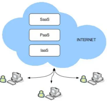
Figure 1: The Cloud computing stack
Cloud computing stack. In [20], the authors proposed a generic Cloud computing stack that classifies Cloud technologies and services into different layers (Figure 1). The purpose of this classification is to facilitate communication about different Cloud technologies and services and to support the design of software systems that wish to use and compose existing
Cloud technologies and services.
IaaS Layer An Infrastructure-as-a-Service (IaaS) Cloud enables on-demand provision of computational resources in the form of virtualized resources in a Cloud provider’s data center. The Service Providers manage a large set of resources including process-ing, storage, network capacity and other fundamental computing resources. Example of this type of Clouds are Eucalytus [24, 23], Nimbus [26], Amazon Elastic Compute Cloud (EC2) [1] and OpenNebula [28].
PaaS Layer At Platform-as-a-Service Cloud, instead of supplying a virtualized infrastruc-ture, the Service Providers supply the software platform which combines program-ming environments and execution environments. Two well known examples of this layer are the Google’s App Engine [14] and Force.com platform.
SaaS Layer Finally, the Software-as-a-Service Cloud (SaaS) consists of applications that run on the Cloud and directly provide services to the customers. The application devel-opers can either use the PaaS layer to develop and run their applications or directly use the IaaS Cloud [20]. Some examples of applications in this layer are Google Docs, Microsoft’s Office Live.
2.2 The Infrastructure-as-a-Service Cloud
With the variety of features provided and technologies used, the Cloud computing paradigm has been drawing attention from many IT providers. Several industrial leaders such as Ama-zon, IBM and scientific organizations are investigating and developing technologies and in-frastructure for Cloud computing.
Amazon Elastic Compute Cloud is a central part of Amazon Cloud computing platform, which provides an elastic virtual computing environment that meets specific customers needs. It enables customers to launch and manage service instances in Amazon’s data cen-ters using APIs or available tools and utilities. Instances are available in different sizes and configurations.
The basic building block of EC2 is the Amazon Machine Image (AMI), which is an en-crypted machine image that contains all necessary information to boot instances. Public AMIs can be downloaded from the Resource Center and users can also public their own private AMIs to the community. After an AMI is launched, the resulting running system is called an instance. Once launched, an instance looks like a traditional host, where users can have a complete control or a root access; and they can interact with it as they would have with any machine.
Users also can choose between multiple instance types, operating systems, and software packages. The Amazon EC2 web services can be accessed using the SOAP web services mes-saging protocol and Query APIs based on HTTP or HTTPS requests. Amazon EC2 allows users to select a configuration of memory, CPU, instance storage, and the boot partition size that is optimal for the needed operating system and application.
Moreover, the Amazon EC2 works in conjunction with other Amazon Web Service such as Amazon Simple Storage Service (Amazon S3), Amazon SimpleDB and Amazon Simple
Figure 2: Eucalyptus hierarchical design
Queue Service (Amazon SQS) to provide a complete solution for computing, query process-ing and storage across a wide range of applications.
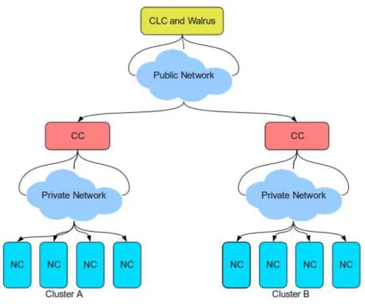
Eucalyptus (Elastic Utility Computing Architecture Linking Your Programs To Useful Systems) is an open-source software infrastructure for implementing elastic, utility, Cloud computing using computing clusters and/or workstation farms. It is known as a private-cloud platform which conforms to both the syntax and the semantic definition of the Amazon APIs and tools suite. The Eucalyptus provides several interesting features such as simple, flexible and modular components. There are four high-level components [24], each with its own Web service interface, that form the system showed in Figure 2.
• Node Controller (NC) executes on every node that is designated to host VM instances. It controls the execution, inspection and terminating of VM instances located on it. • Cluster Controller(CC) runs on a cluster front-end machine; it has three primary
func-tions: schedule incoming instance run requests to run on specific NCs, control the cluster’s virtual network overlay, and gather/report information about the set of NCs. • Storage Controller (Walrus) is a data-storage service which is interface compatible with Amazon’s S3. Walrus provides a mechanism for storing and accessing not only VM images, but also user data.
• Cloud Controller (CLC) is a collection of web services that acts as an entry point into the cloud for users and administrators.
The Nimbus Cloudkit is an open-source implementation of a service that allows a client to lease remote resources by mapping environments, or workspaces onto those resources [18]. Its primary objective is to provide an IaaS Cloud for the experimental needs of scientific and educational projects. The second goal is to better understand the requirements of scientific communities relevant to Cloud paradigm and what needs to be done to address them.
Figure 3: Nimbus Cloud Components
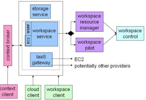
Nimbus allows clients to lease remote resources by deploying VMs on those resources and configuring them to represent an environment desired by the user. With Nimbus toolkit, a provider can build a Cloud, a customer can use Cloud computing services, and a devel-oper or researcher can do their experiments through and open-source architecture. As Nim-bus functionalities grew, all services were make available as a set of components. NimNim-bus architect consists of the four main components [18]: Workspace Service, Workspace Control, Workspace Client, Storage Service. The other components are Context Client, Cloud Client, Con-text Broker, IaaS Gateway, Workspace Pilot, Workspace Resource Manager. All the components can be flexibly selected and composed in a variety of ways since they are small, lightweight and self-contained.
Workspace Service is the main component of the system. It is a stand-alone site VM man-ager and allows a remote client to deploy and manage flexibly-defined groups of VMs. The service contains a Web Service front-end to a VM-based resource manager de-ployed on a site. Currently, it supports two front-ends protocol WSRF (Web Service Resource Framework) and EC2 WSDL (Web Service Description Language).
Workspace Control This component is used to start, stop and pause VMs; it implements VM images reconstruction, management, connects the VMs to the network and deliv-ers contextualization information (currently works with Xen and Kernel-based Virtual Machine (KVM) ).
Workspace Client provides full access to workspace service functionality (in particular, a rich set of networking options) but is relatively complex to use and thus typically wrapped by community specific scripts.
Nimbus Storage Service is known as a "repository" of VM images where users find the needed images or store their own images.
2.3 Focus: Cloud storage services for Virtual Machines
In this section, we overview the Cloud storage services provided by the most important actors in the IaaS Cloud community. We focus on the storage service for Virtual Machines Images.
2.3.1 Amazon Simple Storage Service
Amazon S3 is a storage service for the Internet, which is designed to make web-scale com-puting easier for developers. Amazon S3 has a simple web-services interface that can be used to store and retrieve any amount of data, at any time, from anywhere on the web. Data can be downloaded or used with other AWS (Amazon Web Service) services, such as EC2. It gives any developers access to the same highly scalable, reliable, fast, inexpensive data storage infrastructure that Amazon uses to run its own global network of web sites. The service aims to maximize benefits of scale and to pass those benefits to developers. The best way to think about Amazon S3 is a globally available distributed hash table (DHT) with a high-level access control [15].
A bucket is a basic container for objects in Amazon S3. Every object is contained within a bucket.
Objects are the fundamental entities stored in Amazon S3. Each object has a name, an opaque blob of data (of up to 5GB), and metadata consisting of a small set of predefined entries and up to 4KB of user-specified name/value pairs.
A key is the unique identifier for an object within a bucket. Every object in a bucket has exactly one key. Since a bucket and key together uniquely identify each object, Amazon S3 can be thought of as a basic data map between "bucket + key" and the object itself. Every object in Amazon S3 can be uniquely addressed through the combination of the web service endpoint, bucket name, and key.
Amazon S3 acts both as a VMs repository and users’data keeper. Users need to upload the created or selected their AMIs to Amazon Simple Storage Service (S3), before he can start, stop, and monitor instances deployed AMIs. Standards-based REST and SOAP interfaces are used and designed to work with any Internet-development toolkit. Data can be retrieved using SOAP, HTTP, or BitTorrent. In the case of BitTorrent, the S3 system operates as both a tracker and the initial seed [15].
2.3.2 Walrus
Walrus is a data-storage service which is designed for the Eucalyptus system. It is interface compatible with Amazon S3. The purpose of Walrus is to provide a mechanism for storing and accessing virtual-machine images and user data [24].
In general, Walrus acts as a VM image storage and management service. VM root file-system, kernel and ram-disk images are packaged and uploaded using standard EC2 tool provided by Amazon. These tools compress images, encrypt them using user credentials, and split them into multiple parts that are described in a image description file. Walrus is entrusted with the task of verifying and decrypting images that have been uploaded by users. Because VM images are often quite large, Walrus maintains a cache of images to improve its performance.
Moreover, users can use Walrus to stream data into/out of the Cloud, as well as from instances that they have started on nodes. In order to do this, user can use standard S3 tools since Walrus implements the REST (via HTTP), as well as the SOAP interface that are compatible with Amazon’s S3.
2.3.3 Nimbus storage service
The Nimbus Storage Service is a small, lightweight and self-contained component of Nimbus Cloudkit. This service provides secure management of Cloud disk space, giving each user a "repository" view of VM images they own and images they can launch [18]. In practice, it works in conjunction with Globus GridFTP [10], which supports accessing various storage systems. Thus, the GridFTP server must be installed on a repository node and acts as a front-end server for all requests to access storage system. Whenever Cloud users want to deploy VMs with customized configurations, they upload images to the repository node via a special workspace client called the “Cloud-client”. Then files are transferred from the client to the repository through the GridFTP protocol.
Currently, the Nimbus storage service uses a local file system for the repository node. Therefore, it could face some limitation related to I/O bottleneck when multiple clients access, as well as scalability and replication issues. In our case study, we will address those issues by implementing a BLOB-distributed Nimbus VMs repository by combining the GridFTP server and a BLOB-based distributed storage named BlobSeer. In the next sec-tion, we will detail the two components GridFTP and BlobSeer.
3
Case Study: GridFTP and BlobSeer
3.1 GridFTP: a protocol for Grid computing
3.1.1 GridFTP protocol overview
The GridFTP protocol [10] is a high-performance, secure, reliable data transfer protocol op-timized for high-bandwidth wide-area networks. It extended the FTP protocol defined in [RFC959] and some other IETF documents by adding certain features designed to improve the performance of data movement over a wide-area network [9].
In Grid environments, data-intensive scientific and engineering applications require not only the transfer of large amounts of data (terabytes) between geographically distributed storage systems, but also remote access to large datasets for user application. A number of storage systems are in use in the Grid community. Each of them was designed to satisfy specific needs and requirements for storing, transferring and accessing large datasets. Un-fortunately, most of these storage systems use incompatible and often unpublished protocols and therefore require the use of their own client libraries for data access. Users who wish to access different storage systems are forced to use multiple protocols and/or APIs. These protocols and client libraries effectively partition the datasets available on the grid and ap-plications that require access to data stored in different storage systems must use multiple access methods. Thus it is difficult to efficiently transfer data between these different storage systems. To overcome these incompatible protocols, a universal grid data transfer and access protocol, GridFTP was developed.
GridFTP extends the standard FTP protocol and provides a superset of the features that are offered by the various grid storage systems currently in use. The FTP protocol was chosen because FTP is the protocol most commonly used for data transfer on the Internet and the most likely candidate for meeting the Grid needs. In order to make data available to users, a site needs to install a GridFTP server on a host that can access that data and make sure that there is an appropriate data storage interface available for the storage system holding the data [16]. In general at least one GridFTP server is installed at each resource center.
The following is a summary of key GridFTP features [10]:
Grid Security Infrastructure (GSI) and Kerberos support: When transferring or accessing files, some of GridFTP’s features are critical, such as robust and flexible authentication, integrity, and confidentiality. GridFTP must support the Grid Security Infrastructure (GSI) and Kerberos authentication, with levels of data integrity and/or confidentiality set by the end user. This capability is provided by implementing the GSSAPI (Generic Security Service Application Program Interface) authentication mechanisms defined by RFC 2228, “FTP Security Extensions”.
Third - Party control of data transfer: The authenticated third-party data transfers between storage servers are essential when managing large datasets for distributed communi-ties. Third party operation allows a user or application at one site to initiate, monitor and control a data transfer operation between two other “parties”: the source and des-tination sites for the data transfer. The implementation adds GSSAPI security to the existing third-party transfer capability defined in the FTP standard. The third-party
authenticates itself on a local machine, and GSSAPI operations authenticate the third party to the source and destination machines for the data transfer.
Parallel data transfer: It is one of the key features of GridFTP. On wide-area links, the use of multiple TCP streams in parallel (even between the same source and destination) improves the aggregate bandwidth over using a single TCP stream. GridFTP supports parallel data transfer through FTP command extensions and data channel extensions. Striped data transfer: Data is striped or interleaved across multiple servers, such as in a
DPSS (Distributed Parallel Storage Server) network disk cache or a striped file sys-tem. GridFTP includes extensions that initiate striped transfers, which use multiple TCP streams to transfer data that is partitioned among multiple servers. Striped fers provide further bandwidth improvements over those achieved with parallel trans-fers.There have been defined GridFTP protocol extensions that support striped data transfers.
Partial file transfer: Some applications require the transfer of portions rather than complete files. This is particularly important for applications which require access to relatively small subsets of massive data files. Comparing to the standard FTP supports the trans-fer of complete files or the transtrans-fer of the remainder of a file starting at a particular offset, the GridFTP introduces new FTP commands to support transfers of subsets or regions of a file.
Automatic negotiation of TCP buffer/window sizes: The GridFTP uses optimal settings for TCP buffer/window sizes to have a dramatic impact on data transfer performance and this is especially important in the wide-area. GridFTP extends the standard FTP command set and data channel protocol to support both manual setting and automatic negotiation of TCP buffer sizes for large files and for large groups of small files. Support for reliable and restartable data transfers: Reliable transfer is essential for many
applications and GridFTP incorporates fault tolerant features to handle transient net-work failures, server outages, etc. The FTP standard includes a basic feature for restart-ing failed transfers, but this is not widely implemented. The GridFTP protocol exploits these features and extends them to cover the new data channel protocol.
3.1.2 GridFTP components
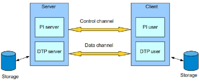
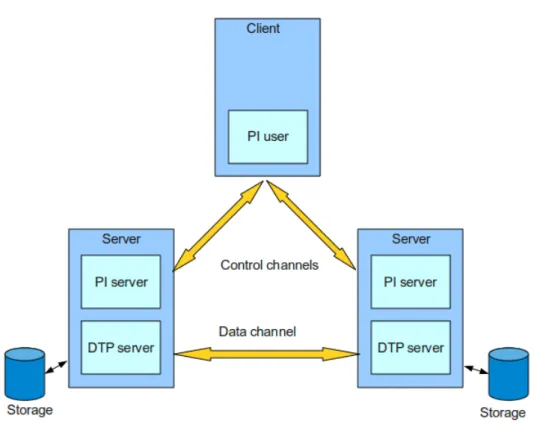
The GridFTP protocol falls within a client-server model, in which one machine (the client) sends orders and the other (the server) awaits requests to carry out actions. It is based on the FTP protocol, which uses two transmision channels for each connection:
Control channel: The channel used for commands.
Data channel: The channel that handles the data operations.
Both the GridFTP client and GridFTP server have distinct components that manage these two types of channels:
DTP (Data Tranfer Process) is the process in charge of accessing the actual data and its move-ment through the data channel. The server side DTP is called SERVER-DTP, the client side DTP is called USER-DTP.
PI (Protocol Interpreter) handles the control channel and it inteprets the protocol, allowing the DTP to be controlled using commands received over the control channel. Since the protocol is asymmetric, the client and the server have different implementation for this component.
• The SERVER-PI is responsible for listening to the commands coming from the USER-PI over the control channel on a data port, establishing the connection for the control channel, receiving FTP commands from the USER-PI over this, re-sponding to them and running the SERVER-DTP.
• The USER-PI is responsible for establishing the connection with the FTP server, sending FTP commands, receiving responses from the SERVER-PI and controlling the USER-DTP if needed.
Configuration The combination of those components creates a server with different capa-bilities. Therefore, we have two types of configuration : a non-striped and a striped config-uration.
Figure 4: The non-striped GridFTP configuration
A non-striped configuration In this configuration, the server PI and the DTP component are combined into one process, thus creating a conventional GridFTP server. (Figure 4).
A striped configuration The server PI and DTP component are seperated into different pro-cesses. Thus, when the control channel and data channel are separate channels, it is possible to send commands from one machine and receive data on another. So, for example it is possible to transfer data between GridFTP servers by passing through a GridFTP client to send control instructions and by transferring information directly
Figure 5: The striped GridFTP configuration
between the two server processes. This configuration is called striping, and it supports the data transfer among multiple servers. A striped server might use one server PI on the head node of a cluster and a DTP on all other nodes (Figure 5).
The GridFTP communication As described in Figure 4, the server PI handles communica-tion on the control channel. In order for a client to contact a GridFTP server, either the server PI must be running as a daemon and listening on a well known port (2811 for GridFTP), or some other service (such as inetd) must be listening on the port and be configured to invoke the server PI. The client PI then carries out its protocol exchange with the server PI. During the preparatory phase of the protocol exchange, the server PI is concerned simply with de-veloping a description of the transfer that is to take place. No communication is necessary with the DTP at this point.
The server PI passes the description of the transfer to the DTP when it receives a com-mand that requires DTP activity. After that, the DTP can carry out the transfer on its own. Once the transfer request is passed to the DTP‘, the server PI simply acts as a relay for trans-fer status information. For example, the server DTP may send performance markers, restart markers, etc., to the server PI, which optionally processes them, and then sends them to the client PI.
PI-to-DTP communications are internal to the server, and thus the protocol used can evolve with no impact on the client. In an early prototype, the GridFTP used Message Pass-ing Interface (MPI), which worked well but required that MPI to be installed. Currently it uses a binary protocol over TCP.
The data channel communication structure is governed by data layout. In general, if the number of nodes at both ends is equal, each node communicates with just one other node. Otherwise, each sender makes a connection to each receiver, and sends data to each receiver based on data offsets.
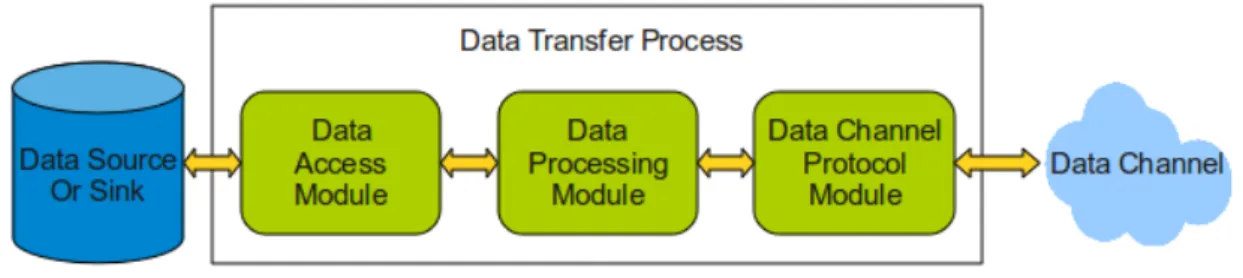
Data Transfer Process The DTP itself is further decomposed into a three-module pipeline [11]. The data-access module provides an interface to data source(s) and/or sink(s). The data processing module performs server-side data processing, if requested by an ex-tended STOR/RETR (ESTO/ERET) command. Finally, the data channel protocol module reads from, and/or writes to, the data channel. This basic structure allows for a wide variety of systems, from simple file server logic (data access module reads/writes files, data process-ing module does nothprocess-ing, data channel protocol module writers/reads the data channel) to more complex and specialized behaviors (e.g., data module generates data dynamically in response to user requests).
Figure 6: The Globus GridFTP data transfer pipeline
DTP Data Access Module This module is responsible for reading from, and/or writing to, a data source or sink. Its public interface includes transfer operations (list, send, receive) and command operations (e.g., make/remove directory, rename, checksum). Different implementations of this interface can be provided. This module is also known as the Data Storage Interface which presents a modular abstract layer to a storage system. DTP Data Processing Module This module allows for (optional) server-side data
process-ing, such as compression, scalprocess-ing, or concatenation of multiple files. Normal (no server side processing) transfers are initiated with the STOR <filename>, for a put, or RETR <filename>, for a get. Data processing modules are invoked for puts and gets via the ESTO (Extended STOR) and ERET (Extended RETR) commands, respectively. Cur-rently the data processing module is functionally implemented within the data access module. The GridFTP team plan to separate this functionality out as a separate module and to allow for chaining of multiple modules.
DTP Data Channel Protocol Module This module handles data channel processing, i.e. the operations required to fetch data from, or send data to, the data channel. A single server may support multiple data channel protocols, in which case the MODE com-mand is used to select the protocol to be used for a particular transfer. Currently,
the Globus eXtensible Input/Output (XIO) system is used as the data channel pro-tocol module interface and currently support two bindings: Stream- mode TCP and Extended Block Mode TCP.
3.1.3 GridFTP data storage interaface
As mentioned in the previous subsection, the Data Storage Interface (DSI) / Data Access module knows how to read and write to the storage system and can optionally transform the data. The interface consists in functions to be implemented such as send (get), receive (put), command (mkdir, rename, checksum), etc. Thus, the different implementations of the DSI are beneficial for both the providers of large datasets and the users of these datasets. The data providers gain a broader user base, because their database would be availabe to any client, while the users gain access to a broader range of storage system and data [19].
The main features of a DSI are:
• It is responsible for reading and writing to the storage system. The transformation of data is optional.
• It consists of several function signatures, which must be filled with suitable semantics for providing a specific functionality.
• It can be loaded at runtime.
• The GridFTP server requests to the DSI module whatever operation it needs from the underlying storage system. Once the DSI performs this operation, it notifies the GridFTP server about the completion and passes the results back to it.
When a new DSI is created, a programmer implements the functions to provide the seman-tics associated with them. Thus, whenever the GridFTP server gets request actions attempt-ing to access the storage system, it passes a request to the loaded DSI module. The DSI then actually services that request and notifies the server when it is finished. However, the most intersting part of DSI is that it hides the details of sending/receving data across the data channel. Once these functions have been implemented for a specific storage system, a client does not need to know or care what is actually providing the data. Furthermore, the server can either be configured with a specific DSI, i.e., it knows how to interact with a single class of storage systems, or one particularly useful function for the extended store/retrieve (ESTO/ERET) functionality.
Currently, DSIs do exist for some kind of storage system: • POSIX-compliant local file systems.
• The Storage Resourece Broker (SRB) [29].
• The High Performance Storage System (HPSS) [5].
• The NeSt from the Condor team at the University of Wisconsin-Madison [7]. • The flexible multiagent parallel file system for clusters (MAPFS) [27].
Those customized DSIs make access to attached storage available to any clients or applica-tions through the GridFTP protocol. Our goal is implemeting a blob-based DSI that enables BlobSeer as a back-end storage system for Cloud.
3.2 BlobSeer: a management service for binary large object
BlobSeer is a management service for binary large objects (BLOBs). It is developed within the KerData Project-Team, at IRISA, France, and hosted at❜❧♦❜s❡❡r✳❣❢♦r❣❡✳✐♥r✐❛✳❢r.
3.2.1 BlobSeer’s principles
BlobSeer [22, 21] addresses the problem of storing and efficiently accessing very large, un-structured data objects, in a distributed environment. It focuses on heavy access concurrency where data is huge, mutable and potentially accessed by a very large number of concurrent, distributed processes. In fact, this kind of concurrent access is becoming more and more popular for scientific applications, multimedia processing, or astronomy over recent years.
BlobSeer accommodates the huge BLOBs (on the order of TBs) by splitting each BLOB into small, fixed-sized pages that are scattered across data provides. Further, BlobSeer pro-vides the clients with efficient fine-grained access to the BLOB, without locking the BLOB itself. In order to deal with the mutable data problem, BlobSeer introduces an efficient ver-sioning scheme which allows the client not only to roll back data changes when desired, but also enables it to access different version of the BLOB within the same computation. More-over, the metadata management system is built on top of a distributed hash table (DHT), thus preventing the metadata servers from becoming performance bottlenecks.
3.2.2 Architecture overview
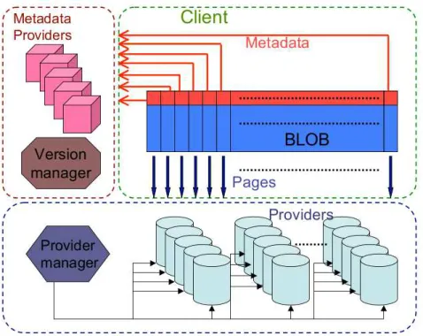
The system consists of distributed processes, that communicate through remote procedure calls (RPCs). A physical node can run one or more processes and, at the same time, may play multiple roles from the ones mentioned below.
Clients. Clients may issue ❈❘❊❆❚❊, ❲❘■❚❊, ❆PP❊◆❉ and ❘❊❆❉ requests. There may be multiple concurrent clients. Their number can dynamically vary in time without noti-fying the system.
Data providers. Data providers physically store and manage the pages generated by❲❘■❚❊ and❆PP❊◆❉ requests. New data providers are free to join and leave the system in a dynamic way.
The provider manager. The provider manager keeps information about the available data providers. When entering the system, each new joining provider registers with the provider manager. The provider manager tells the client to store the generated pages in the appropriate data providers, according to a strategy aiming at global load balancing. Metadata providers. Metadata providers physically store the metadata, allowing clients to find the pages corresponding to the various BLOB versions. Metadata providers may be distributed to allow an efficient concurrent access to metadata.
Figure 7: The BlobSeer Architecture.
The version manager. The version manager is the key actor of the system. It registers up-date requests (❆PP❊◆❉ and ❲❘■❚❊), assigning BLOB version numbers to each of them. The version manager eventually publishes these updates, guaranteeing total ordering and atomicity.
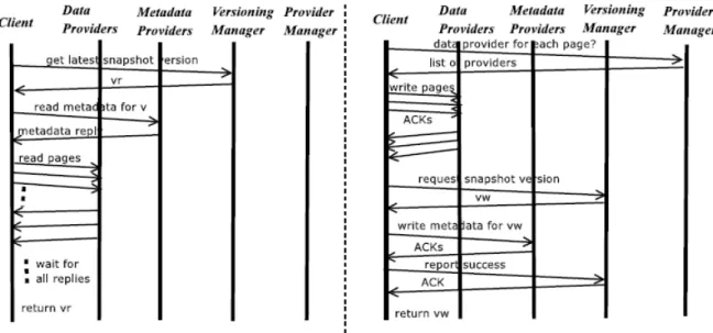
Internal interactions inside BlobSeer The interactions between the entities of BlobSeer are briefly illustrated in Figure 8.
For a WRITE request, the client contacts the provider manager to obtain a list of providers, one for each page of the BLOB segment that needs to be written. Then, the client contacts the providers in the list in parallel and requests them to store the pages. Each provider executes the request and sends an acknowledgment to the client. When the client has received all the acknowledgments, it contacts the version manager, requesting a new version number. This version number is then used by the client to generate the correspond-ing new metadata. After receivcorrespond-ing the acknowledgment, the client reports the success to the version manager.
A READ request begins with the client contacting the version manager to get the version of the corresponding BLOB. If the specified version is available the client contacts the meta-data provider to retrieve the metameta-data associated with the pages of the requested segment for the requested version. After gathering all the metadata, the client contacts, in parallel, the data providers that store the corresponding pages.
BlobSeer file-oriented API BlobSeer currently provides some primitives for accessing the BLOBs. We are interested in BlobSeer’s C oriented interface which maps blobs to
file-Figure 8: Internal interactions inside BlobSeer: READ(left) and WRITE(right).
names and exposes a set of high-level operations. It consists of an API which enables the interaction within the file namespace (eg.: commands to create, delete or list directories; create, open or delete files) and a file handler API for the file operations (eg.: read, write, append). The full APIs’description is provided in the Appendix A section.
4
Contribution: a BLOB-based data storage back-end for GridFTP
4.1 Motivating scenario
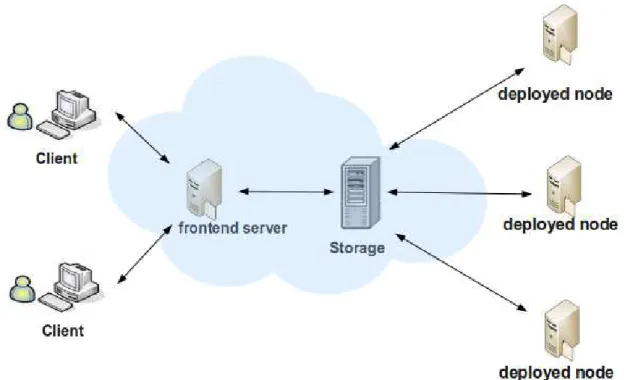
In Cloud computing, a general scenario happens when the Cloud users release remote re-sources by deploying VMs into reserved rere-sources. As described in Figure 9, first users request reserved resources which are called deployed nodes. Then, users choose either their uploaded VMs or standard VMs provided in VMs repository via a front-end server. After that, VMs are launched into the deployed nodes. In our case study of Nimbus Cloudkit, the GridFTP server act as a front-end server that serves requests for uploading/downloading VMs from the client. Thus, the GridFTP protocol is used for the transfer process.
In our motivating scenario which focus on uploading VMs, the combination of GridFTP Server and BlobSeer aims to have a GridFTP server on-top of BlobSeer system which can leverage the concurrency access to a large unstructed data object in distributed system. In addition, the BlobSeer DSI promise a chance of achieving scalable file I/O performance.
Figure 9: The Cloud Virtual Machine interaction within Cloud user
Focusing on the GridFTP server, it is possible to have the BlobSeer service as a back-end by modifying one of its modules. This module is the Data Storage Interface (DSI), whose re-sponsibility is to read and write to a specific storage system. BlobSeer DSI enables GridFTP clients to read and write data to the BlobSeer system. As we have mentioned in the previ-ous subsection related the architecture of BlobSeer, the GridFTP server should embed the BlobSeer client library to interact with BlobSeer system.
GridFTP DSI presents a modular abstraction layer to a storage system, it manages the GridFTP data access and acts as an interface between the server and the storage system.
• When a BlobSeer DSI is created, we implement the set of functions to provide the semantics associated with them.
• The DSI can be loaded and switched by GridFTP Server option at runtime.
• When the server requires action from the storage system, for example create directory, get data,etc, it passes a request to the loaded DSI module.
• The DSI then serves that request and interacts with BlobSeer through the BlobSeer Client Interface, then tells the server when it is finished.
We focus on the most important operations that have to be implemented for a DSI, normally the data transfer commands: the send operation from client to server (put) and receive operation (get)
4.2 Design overview
The BlobSeer Data Storage Interface (DSI) is as an extension to the GridFTP server that allows it to interact with BlobSeer.
4.2.1 Architecture
Figure 10: The BlobSeer DSI Architecture
The Figure 10 shows the architecture of the system. There are 4 major components: BlobSeer System This is where the data is stored. It is acceesed by the GridFTP Server via
BlobSeer DSI This component is the heart of the system. It acts like a bridge to connect GridFTP and BlobSeer. It serves all requests dispatched from the GridFTP and trans-lates all of them into BlobSeer specific calls. Thus, all requested operations and data transfers are routed through this component.
GridFTP Server A standard GridFTP server is loaded with dsi option BlobSeer DSI.
GridFTP Client A GridFTP client, like❣❧♦❜✉s−✉r❧−❝♦♣②. There is no change in this compo-nent.
As we can see in the Figure 10, there are two independent parts of the architecture that can improve the performance of the data transfer operation, both from the client to the server (PUT operations) and from the server to the client (GET operations). Firstly, the parallelism and striping features provided by the GridFTP protocol can be optimized. Secondly, the reads and writes to the BlobSeer system can be performed in parallel. Combining these two steps can improve the performance and minimize the bottleneck of having a single GridFTP server. Based on this architecture we propose two versions of a BlobSeer-based implemen-tation of the DSI with synchronous and asynchronous approaches.
4.2.2 Inner operation
DSI bones: A GridFTP session is defined from the time a client is authorized to use the server until the time it is disconnected. GridFTP server uses GSI as the authentication service for a connection. In the life time of a session, the client issues various commands to the GridFTP server. Some of these commands require access to the storage system, and thus require calls to the DSI. Whenever such a command is received, the server calls the BlobSeer DSI interface function that implements the specific operations needed by the server.
Every DSI must register itself with the Globus extensions module properly. For this rea-son, the GridFTP team provided a skeleton DSI upon which a developer can build. Based on this skeleton, we created some functions for our BlobSeer DSI. The Figure 11 shows activities of a GridFTP client and a GridFTP releated to those function.
❣❧♦❜✉s❴❧❴❣❢s❴❜❧♦❜s❡❡r❴❛❝t✐✈❛t❡✭✮✿ This activate function will load the BlobSeer DSI into the GridFTP server. This is called when the server sets the parameter−❞s✐ ❜❧♦❜s❡❡r❞s✐ ❣❧♦❜✉s❴❧❴❣❢s❴❜❧♦❜s❡❡r❴❞❡❛❝t✐✈❛t❡✭✮✿ This function deactivates the loaded BlobSeer DSI. ❣❧♦❜✉s❴❧❴❣❢s❴❜❧♦❜s❡❡r❴st❛rt✭✮✿ This function is called by the server when the user
at-temps to login. In this funtion we can check and initialize the session. If there is a failure, the client will be rejected.
❣❧♦❜✉s❴❧❴❣❢s❴❜❧♦❜s❡❡r❴❞❡str♦②✭✮✿ This is called when a session ends, ie. the client quits or disconnects. The DSI cleans up all memory allocated within the session.
❣❧♦❜✉s❴❧❴❣❢s❴❜❧♦❜s❡❡r❴s❡♥❞✭✮✿ This function is called when the client wants to upload a file into the server. It is equivalent to a send operation put.
❣❧♦❜✉s❴❧❴❣❢s❴❜❧♦❜s❡❡r❴r❡❝✈✭✮✿ This interface function is called when the client requests that a file is downloaded from the server. It is invoked by a receive operation get.
❣❧♦❜✉s❴❧❴❣❢s❴❜❧♦❜s❡❡r❴❝♦♠♠❛♥❞✭✮ This interface function is called when the client sends a ’command’. Examples of commands include mkdir, rmdir, delete.
❣❧♦❜✉s❴❧❴❣❢s❴❜❧♦❜s❡❡r❴st❛t✭✮✿ This interface function is called whenever the server needs information about a given file or resource. It is called when a list command is sent by the client, when the server needs to verify that a file exists and has the proper permissions, etc.
Figure 11: The BlobSeer DSI Activity
On the other hand, for implementing BlobSeer DSI, we used some helper functions provided by GridFTP. Those are described in the Appendix B.
Globus Asynchronous Event Handling In addition, the Globus Toolkit uses an asyn-chronous event model, which does not follow the line-by-line procedure, instead events are given handler functions. In this model, a user registers for an event with the system, giving it a handler function. Whenever the event occurs the system calls the user’s handler function. This model allows simultaneous event and data processing.
The heart of the Globus event model is the callback library, which provides an API for asynchronous time events. In order to use the API for events, the user must implement a function (the callback) that is called when the events has occurred and process it. The register callback function named❣❧♦❜✉s❴❝❛❧❧❜❛❝❦❴r❡❣✐st❡r❴♦♥❡s❤♦t✭✮ should be called before the events occurs.
In a non-threaded build, there is a single thread of execution, thus a list of events is maintained by the system. In a threaded build a user would see two threads [3] (pos-sibly more): the main thread that is executing the loop in main() and an internal Globus thread that is handling polling of events. The Globus thread is created when the user calls ❣❧♦❜✉s❴♠♦❞✉❧❡❴❛❝t✐✈❡✭●▲❖❇❯❙❴❈❖▼▼❖◆❴▼❖❉❯▲❊✮. This function must be called before any API functions in the ❣❧♦❜✉s❴❝♦♠♠♦♥ package can be used. This is another command theme in Globus: all modules must be activated before use and deactivated when finished. The event thread polls all events and as they become ready the function associated with them is dispatched.
We would apply this model for our BlobSeer DSI asynchronous approach.
4.3 Implementation
As mentioned in the previous subsection, we actually propose two approaches to implement BlobSeer DSI. The first is based on synchronous event handling between reading the data stream from the client and writing it into the BlobSeer storage. The second one uses an asynchronous event handling model for those operations. The second one outweighs the first because it provides higher throughput as well as it eliminates the bottleneck effect by using the thread option.
Synchorounous Approach Our first implementation is very simple. The main idea is to synchronize the two operation of sending/receiving data in data channel and writing/read-ing data in the BlobSeer storage. In this way, it is easy to handle the data flow from the client to the BlobSeer system. However, it also has some drawbacks, since all the operations related to data channel must wait for the completion of writes or reads into BlobSeer stor-age. Thus the parallelism feature of GridFTP and BlobSeer is not optimized. The operations within this system are described on the Figure 12.
As an example, we describe the steps that compose the put operation: • The client sends a request to the GridFTP Server to store a file.
• Before the file transfer, the GridFTP sever determines an optimized concur-rency and block size parameters passing the ❣❧♦❜✉s❴❣❢s❴♦♣❡r❛t✐♦♥❴t data type to the functions : ❣❧♦❜✉s❴❣r✐❞❢t♣❴s❡r✈❡r❴❣❡t❴♦♣t✐♠❛❧❴❝♦♥❝✉rr❡♥❝② and ❣❧♦❜✉s❴❣r✐❞❢t♣❴s❡r✈❡r❴❣❡t❴❜❧♦❝❦❴s✐③❡
Figure 12: Data interaction for the BlobSeer Synchronous Approach: put (left), get (right)
• The GridFTP sever call the ❣❧♦❜✉s❴❣r✐❞❢t♣❴s❡r✈❡r❴❜❡❣✐♥❴tr❛♥s❢❡r function to start the transfer.
• The GridFTP server reads data from the data channel into its data buffer. Then the buffer is written to the BlobSeer system.
• When the GridFTP server gets the acknowledgement of successful write into the stor-age, it will notify the client about the successful transfer. After that, it requests a new read from the data channel.
• This procedure repeats until the end of file is reached.
• The function ❣❧♦❜✉s❴❣r✐❞❢t♣❴s❡r✈❡r❴✜♥✐s❤❡❞❴tr❛♥s❢❡r indicates the end of transfer. Asysnchronous Approach Analyzing the internal interactions inside the GridFTP server, we propose a second approach which is more efficient than the previous one, and improves the I/O performance of the system. In this implementation, we propose an asynchronous event handling between BlobSeer read/write operations and GridFTP send/receive opera-tions. In order for the BlobSeer client to write data into the BlobSeer system simultaneously with the reads performed by the GridFTP server, we define a new server queue buffer. The main purpose of the queue is to store incoming data, and this will be used for write/read operations to the BlobSeer system.
There are some modifications to the previous approach, for example for the put opera-tion:
• The client sends a request to the GridFTP Server to store a file.
• Before the file transfer, the GridFTP sever determines an optimized concurrency degree and block size
Figure 13: Data interaction for the BlobSeer Asynchronous Approach: put (left), get (right)
• The GridFTP server calls the ❣❧♦❜✉s❴❣r✐❞❢t♣❴s❡r✈❡r❴❜❡❣✐♥❴tr❛♥s❢❡r function to start the transfer.
• The GridFTP continuously gets data from the data channel. It will be stored in a new buffer which is added to the queue.
• The BlobSeer DSI write data stored in the queue buffers to the BlobSeer storage. The buffers are freed whenever the data is written.
• This procedure repeats until the end of file is reached and all buffers are written into storage. It means that the buffer queue is empty, and the server receives notifications from all the buffers.
• The function ❣❧♦❜✉s❴❣r✐❞❢t♣❴s❡r✈❡r❴✜♥✐s❤❡❞❴tr❛♥s❢❡r indicates the end of the transfer. The asynchronous approach described above enables us to get the data from the stream and write the previous incoming data at the same time. It will leverage the parallelism both of GridFTP and BlobSeer read/write operations.
5
Experimental evaluation
In this section, we carried out some experiments as a proof of concept for our implementa-tion. First, we compare our implementation of BlobSeer DSI with file system DSI. Secondly, we analyze the implementation under concurrent accesses scenario, where multiple clients concurrently send a file to the GridFTP server.
Evaluations have been performed on the Grid’5000 [30] testbed, an experimental Grid platform gathering 9 sites geographically distributed in France. In each experiment, we use one node for each GridFTP client and each GridFTP server. We also used 15 nodes for BlobSeer system. Nodes are outfitted with Intel Xeon EM64T 3GHz and 2GB of RAM. Intr-cluster measured bandwidth is 110MB/s for TCP sockets with MTU set at 1500 B, latency is 0.1 ms.
❇❧♦❝❦❴s✐③❡ t❡st We first ran a set of experiments to evaluate the performance of our im-plementation. Our configuration was the following : one GridFTP client ran on 1 node, another node is for GridFTP server. We also deployed BlobSeer system as following : a ver-sion manager, a metadata provider, a provider manager, each is deployed on a single node, the other 10 nodes hosted data providers. In the GridFTP protocol, the ❜❧♦❝❦❴s✐③❡ parameter is a very important parameter need to consider, since it corresponds to the amount of data transfered between client to the server for each read or write. In our implementation, we set the ♣❛❣❡❴s✐③❡ parameter of BlobSeer equivalent to the ❜❧♦❝❦❴s✐③❡ parameter. For each test, a 1GB filesize is transfered from GridFTP client to GridFTP server.
Figure 14: I/O access comparison between local file system DSI, BlobSeer DSI synchronous and aysnchronous approaches
Results are shown in Figure 14: with the BlobSeer DSI synchronous approach, the I/O bandwidth is lower than using local file system DSI, since there are wait events between two operations of reading data from data channel and writing it into BlobSeer storage. How-ever, it can be observed that the I/O bandwidth of BlobSeer DSI asynchronous approach corresponds to the local file system DSI results. In that case, there is not much difference between BlobSeer DSI asynchronous approach and local file system DSI, and it was nearly 35% improvement comparing to the BlobSeer DSI synchronous approach.
Large data transfer In the second experiment, we evaluate the bandwidth performance when the client transfers a file with different size to the server. We use again the previous configuration for BlobSeer storage and set the ❜❧♦❝❦❴s✐③❡ parameter to 4MB.
Figure 15: I/O througput performance when large data files transferred
The obtained results are represented in Figure 15 :the I/O bandwidth of the BlobSeer DSI asynchronous approach slightly higher than using the local file system DSI. We observe a very good I/O throughput result around 70MB/s.
Access concurrency Our final experiment evaluates the BlobSeer DSI performance in a scenario where multiple clients upload their VMs into repository. In this experiment, we consider that each clients transfers a virtual machine that contains 1GB of data. The same configuration was used for the GridFTP server, BlobSeer system and network. The❜❧♦❝❦❴s✐③❡ of the GridFTP server was set to 4MB, and multiple GridFPT clients share the same LAN network interface when connecting to the GridFTP server.
Figure 16 indicates that the aggregated bandwidth of BlobSeer DSI asynchronous ap-proach is better than that of local file system DSI. The aggregated bandwidth of the local file system DSI decreases since the local file system becomes a bottleneck for I/O access. The BlobSeer DSI is increasing, because of the efficient concurrent writes in BlobSeer. For exam-ple, as shown in Figure 16, the aggregated bandwidth drops from 70MB/s for a single client
Figure 16: Aggregated througput of local file DSI and BlobSeer DSI asynchronous approach when concurrent clients put different files into storage
to 60MB/s for 2 concurrent client in the case of local file system DSI. While it is increasing to 80MB/s in the case of BlobSeer DSI asynchronous approach.
6
Conclusion
6.1 Contribution
In this paper, we presented a general overview of the VMs repository in IaaS Cloud com-puting. Then, we addressed some limitations related to the scalability, I/O bottleneck and centralized architecture of existing Nimbus storage service. In order to solve them for the scenario of storing VMs, we proposed our approach to build a distributed VMs repository for Cloud within the case study of Nimbus Cloudkit. To make sure data stored by BlobSeer service available to the other Cloud Services, we implemented a BlobSeer DSI that works with the GridFTP protocol.
The combinition of GridFTP and BlobSeer, on one hand, can provide high throughput with the large data transfer, on the other hand, the clients can benefit from replication and distributed features of BlobSeer when requesting a download or deployed a VM from the VMs repository which is a BlobSeer storage. Moreover, in our design and implementation of BlobSeer DSI, we have taken into account scalability, bandwidth efficiency so that we proposed two approaches of synchronous and asynchronous. According to our approaches, an implementation was experimented on the Grid’5000 testbed. The preliminary results show that our BlobSeer DSI’s capable of working for transfer large file in Cloud environment. We also got some good initial feedback from the GridFTP team for those results.
6.2 Future work
As future work, we are planning to improve the performance of BlobSeer DSI by using the striping features of the GridFTP protocol. We are considering to expand our configuration by using multiple GridFTP servers as frontends for the same BlobSeer system. This approach would eliminate the bottleneck of having a single GridFTP server when a large number of clients concurrently access the storage back-end. Further, we believe that the next step would be take advantages of the versioning features for BlobSeer DSI, since the Cloud storage ser-vice is not only used for storing VMs but also users’data. Finally, we intend to compare our prototype with SRB-DSI, HDFS-DSI.
A
Appendix : Full BlobSeer file-oriented APIs
A.1 The namespace handler APIs
♥s❴✐♥✐t✭❝♦♥st ❝❤❛r ✯❝♦♥✜❣❴✜❧❡✱ ❜❧♦❜❴❡♥✈❴t ✯❡♥✈✮
This primitive initializes the environment used in BlobSeer. It takes the configuration file as the input and initializes the variable env.
♥s❴✜♥❛❧✐③❡✭❜❧♦❜❴❡♥✈❴t ✯❡♥✈✮
This primitive finializes the environment used in BlobSeer. It destroys all related used variable and memory.
♥s❴✐♥✐t✐❛❧✐③❡◆❛♠❡s♣❛❝❡❍❛♥❞❧❡r✭❜❧♦❜❴❡♥✈❴t ✯❡♥✈✱ ♥s❴❤❛♥❞❧❡r❴t ✯♥s❴❤❛♥❞❧❡r✮
This primitive initializes the namespace handler for BlobSeer. The env variable identi-fies the BlobSeer environment, while the♥s❴❤❛♥❞❧❡r variable identifies the namespace handler.
♥s❴❢r❡❡✭❜❧♦❜❴❡♥✈❴t ✯✴✯❡♥✈✯✴✱ ♥s❴❤❛♥❞❧❡r❴t ✯♥s❴❤❛♥❞❧❡r) This primitive destroys the namespace handler. ♥s❴♠❦❞✐r✭♥s❴❤❛♥❞❧❡r❴t ✯♥s❴❤❛♥❞❧❡r✱ ❝♦♥st ❝❤❛r ✯♣❛t❤✮
This primitive creates a directory handled by♥s❴❤❛♥❞❧❡r, the directory name is given by the path variable.
♥s❴❡①✐sts✭♥s❴❤❛♥❞❧❡r❴t ✯♥s❴❤❛♥❞❧❡r✱ ❝♦♥st ❝❤❛r ✯♣❛t❤✱ ✉✐♥t✽❴t ✯r❡s✉❧t✮
This primitive checks whether a file name given by path exists in the namespace or not.
♥s❴✐s❋✐❧❡✭♥s❴❤❛♥❞❧❡r❴t ✯♥s❴❤❛♥❞❧❡r✱ ❝♦♥st ❝❤❛r ✯♣❛t❤✱ ✐♥t ✯r❡s✉❧t✮
This primitive checks whether the given path is a file or a directory. ♥s❴r❡♥❛♠❡✭♥s❴❤❛♥❞❧❡r❴t ✯♥s❴❤❛♥❞❧❡r✱ ❝♦♥st ❝❤❛r ✯♣❛t❤✱ ❝♦♥st ❝❤❛r ✯♥❡✇P❛t❤✮
This primitive renames the given path to the newPath. ♥s❴❞❡❧❡t❡❋✐❧❡✭♥s❴❤❛♥❞❧❡r❴t ✯♥s❴❤❛♥❞❧❡r✱ ❝♦♥st ❝❤❛r ✯♣❛t❤✮
This primitive deletes a file specified by variable path.
♥s❴❧✐st❉✐r✭♥s❴❤❛♥❞❧❡r❴t ✯♥s❴❤❛♥❞❧❡r✱ ❝♦♥st ❝❤❛r ✯♣❛t❤✱ ❢♠❡t❛❞❛t❛❴❧✐st❴t ✯❧✐st✮ This primitive lists directory information given in the path variable. ♥s❴❝r❡❛t❡❋✐❧❡✭♥s❴❤❛♥❞❧❡r❴t ✯♥s❴❤❛♥❞❧❡r✱ ❝♦♥st ❝❤❛r ✯♣❛t❤✱ ✉✐♥t✻✹❴t ♣❛❣❡❴s✐③❡✱
✉✐♥t✸✷❴t r❡♣❧✐❝❛❴❝♦✉♥t✮ A ♥s❴❝r❡❛t❡❋✐❧❡ operation creates a file handled by variable ♥s❴❤❛♥❞❧❡r. The ♣❛❣❡❴s✐③❡ parameters specifies the size of the pages that the BLOB will be fragemented into. The number of BLOB replicas is specified byr❡♣❧✐❝❛❴❝♦✉♥t.
A.2 The file handler APIs
♥s❴❣❡t❋✐❧❡❍❛♥❞❧❡r✭♥s❴❤❛♥❞❧❡r❴t ✯♥s❴❤❛♥❞❧❡r✱ ❝♦♥st ❝❤❛r ✯♣❛t❤✮
This primitive returns the file handler for a file for which the name is specified in variable path.
♥s❴❞❡str♦②❋✐❧❡❍❛♥❞❧❡r✭♥s❴❤❛♥❞❧❡r❴t ✯♥s❴❤❛♥❞❧❡r✱ ❢❜❧♦❜❴t ✯ ❤❛♥❞❧❡r✮ This primitive destroys the file handler.
❢❜❧♦❜❴❣❡t❧❛t❡st✭❢❜❧♦❜❴t ✯❢❜❧♦❜✮
The❢❜❧♦❜❴❣❡t❧❛t❡st returns the lastest version of the fblob. ❢❜❧♦❜❴❣❡ts✐③❡✭❢❜❧♦❜❴t ✯❢❜❧♦❜✱ ✉✐♥t✸✷❴t ✈❡rs✐♦♥✮
This primitive returns the size in bytes of a specified version of the BLOB handled by fblob.
❢❜❧♦❜❴❣❡t❴♣❛❣❡❴s✐③❡✭❢❜❧♦❜❴t ✯❢❜❧♦❜✮
The❢❜❧♦❜❴❣❡t❴♣❛❣❡❴s✐③❡ operation returns the page size in bytes of a specified version of the BLOB handled by fblob.
❢❜❧♦❜❴r❡❛❞✭❢❜❧♦❜❴t ✯❢❜❧♦❜✱ ✉✐♥t✸✷❴t ✈❡rs✐♦♥✱ ✉✐♥t✻✹❴t ♦✛s❡t✱ ✉✐♥t✻✹❴t s✐③❡✱ ❝❤❛r ✯❜✉✛❡r✮ The ❢❜❧♦❜❴r❡❛❞ operations takes a segment (specified by an offset and a size) from a BLOB (specified by fblob) and puts it into a buffer. The version of the BLOB from which the segment must be read is also provided.
❢❜❧♦❜❴✇r✐t❡✭❢❜❧♦❜❴t ✯❢❜❧♦❜✱ ✉✐♥t✻✹❴t ♦✛s❡t✱ ✉✐♥t✻✹❴t s✐③❡✱ ❝❤❛r ✯❜✉✛❡r✮
The ❢❜❧♦❜❴✇r✐t❡ primitive modifies a BLOB identified by its handler fblob, by writing the contents of a buffer of length size at a specified offset within the BLOB. The function call generates a new version number, corresponding to the new version of the BLOB. ❢❜❧♦❜❴❛♣♣❡♥❞✭❢❜❧♦❜❴t ✯❢❜❧♦❜✱ ✉✐♥t✻✹❴t s✐③❡✱ ❝❤❛r ✯❜✉✛❡r✮
This primitive calls an append to the current version of BLOB specified by fblob. The length of contents stored in buffer determined by variable buffer and length is written to the BLOB. This function also generates a new version of the BLOB.
B
Appendix: Globus GridFTP helper functions
In this appendix, we describe some helper functions provided by GridFTP for implementing BlobSeer DSI.
❣❧♦❜✉s❴❣r✐❞❢t♣❴s❡r✈❡r❴❜❡❣✐♥❴tr❛♥s❢❡r✭✮ This function tells the sever to start the data channel for communiction of specific function as send/recv.
❣❧♦❜✉s❴❣r✐❞❢t♣❴s❡r✈❡r❴✜♥✐s❤❡❞❴tr❛♥s❢❡r✭✮ This tells the server that a specific function has completed. All data passing function must have a finish function.
❣❧♦❜✉s❴❣r✐❞❢t♣❴s❡r✈❡r❴r❡❣✐st❡r❴r❡❛❞✭✮write()| This is how the file data is transfered be-tween the DSI and the server.
❣❧♦❜✉s❴❣r✐❞❢t♣❴s❡r✈❡r❴✉♣❞❛t❡❴❜②t❡s❴✇r✐tt❡♥✭✮ This is called when a BlobSeer DSI suc-cessfully completes a write to its own storage system. This allows performance and restart markers to be generated.
❣❧♦❜✉s❴❣r✐❞❢t♣❴s❡r✈❡r❴❣❡t❴♦♣t✐♠❛❧❴❝♦♥❝✉rr❡♥❝②✭✮ This tells the number of outstanding reads or writes we should have based on the parallelism.
❣❧♦❜✉s❴❣r✐❞❢t♣❴s❡r✈❡r❴❣❡t❴❜❧♦❝❦❴s✐③❡✭✮ This function indicates the buffer size used by server when transferring data from the client. It returns a ❜❧♦❝❦❴s✐③❡ value, which is very important to optimize the performance. In our implementation, we optimized the ♣❛❣❡❴s✐③❡ value in BlobSeer to be equal to the ❜❧♦❝❦❴s✐③❡ value.
References
[1] Amazon Elastic Compute Cloud (EC2),❤tt♣✿✴✴❛✇s✳❛♠❛③♦♥✳❝♦♠✴❡❝✷✴. [2] Amazon Simple Storage Service (S3),❤tt♣✿✴✴❛✇s✳❛♠❛③♦♥✳❝♦♠✴s✸✴.
[3] Globus Toolkit 4.0: Asynchronous Event Handling,❤tt♣✿✴✴✇✇✇✳❣❧♦❜✉s✳♦r❣✴t♦♦❧❦✐t✴❞♦❝s✴ ✹✳✵✴❣❧♦❜✉s✲❛s②♥❝✳❤t♠❧.
[4] Hadoop Gridftp,❤tt♣s✿✴✴t✇✐❦✐✳❣r✐❞✳✐✉✳❡❞✉✴❜✐♥✴✈✐❡✇✴❙t♦r❛❣❡✴❍❛❞♦♦♣●r✐❞❋❚P.
[5] Hpss module for Gridftp: Administrator’s guide, ❤tt♣✿✴✴✇✇✇✳❤♣ss✲❝♦❧❧❛❜♦r❛t✐♦♥✳♦r❣✴ ●r✐❞❋❚P❍P❙❙✳s❤t♠❧.
[6] Ibm Blue Cloud Project,❤tt♣✿✴✴✇✇✇✳✐❜♠✳❝♦♠✴✐❜♠✴❝❧♦✉❞✴. [7] Nest: Network Storage,❤tt♣✿✴✴✇✇✇✳❝s✳✇✐s❝✳❡❞✉✴❝♦♥❞♦r✴♥❡st✴. [8] Science Clouds,❤tt♣✿✴✴✇✇✇✳s❝✐❡♥❝❡❝❧♦✉❞s✳♦r❣✴.
[9] B. Allcock, I. Mandrichenko, and T. Perelmutov. Gridftp v2 protocol description, 2005. [10] W. Allcock, J. Bester, J. Bresnahan, A. Chervenak, L. Liming, S. Tuecke, Status Of This
Memo, L. Liming, and S. Tuecke. Gridftp: Protocol extensions to ftp for the grid. GWD-R (GWD-Recommendation), page 3, 2001.
[11] William Allcock, John Bresnahan, Rajkumar Kettimuthu, Michael Link, Catalin Du-mitrescu, Ioan Raicu, and Ian Foster. The globus striped gridftp framework and server. In In SC ’05: Proceedings of the 2005 ACM/IEEE conference on Supercomputing, 2005. [12] Rajkumar Buyya, Chee Shin Yeo, and Srikumar Venugopal. Market-oriented cloud
computing: Vision, hype, and reality for delivering it services as computing utilities. In HPCC’08: Proceedings of the 2008 10th IEEE International Conference on High Performance Computing and Communications, pages 5–13, 2008.
[13] Tuan-Viet DINH. Cloud Data Management, Bibliography Report, ENS de Cachan,❢t♣✿ ✴✴❢t♣✳✐r✐s❛✳❢r✴❧♦❝❛❧✴❝❛♣s✴❉❊P❖❚❙✴❇■❇▲■❖✷✵✶✵✴❉✐♥❤❴❱✐❡t✲❚✉❛♥✳♣❞❢, Febuary 2010. [14] Google App Engine. ❤tt♣✿✴✴❛♣♣❡♥❣✐♥❡✳❣♦♦❣❧❡✳❝♦♠.
[15] Simson Garfinkel. Commodity Grid computing with Amazon S3 and EC2. Login, USENIX, 2007.
[16] Christian Grimm and Harald Schwier. Empirical analysis of tcp variants and their im-pact on Gridftp port requirements. Networking and Services, International conference on, 0:24, 2007.
[17] Brian Hayes. Cloud Computing. Commnication of the ACM, 7:9–11, July 2008.
[18] K. Keahey, R. Figueiredo, J. Fortes, T. Freeman, and M. Tsugawa. Science clouds: Early experiences in cloud computing for scientific applications. In Cloud Computing and Its Application 2008 (CCA -08) Chicago,, October 2008.