HAL Id: hal-00112273
https://hal.archives-ouvertes.fr/hal-00112273
Submitted on 17 Feb 2020
HAL is a multi-disciplinary open access
archive for the deposit and dissemination of
sci-entific research documents, whether they are
pub-lished or not. The documents may come from
teaching and research institutions in France or
abroad, or from public or private research centers.
L’archive ouverte pluridisciplinaire HAL, est
destinée au dépôt et à la diffusion de documents
scientifiques de niveau recherche, publiés ou non,
émanant des établissements d’enseignement et de
recherche français ou étrangers, des laboratoires
publics ou privés.
Nondestructive damage evaluation of reinforced concrete
structure using infrared thermography
M. P. Luong
To cite this version:
M. P. Luong.
Nondestructive damage evaluation of reinforced concrete structure using infrared
thermography. Nondestructive evaluation of aging materials and composites IV, pp.98-107, 2000,
�10.1117/12.385481�. �hal-00112273�
Nondestructive damage evaluation of reinforced concrete structure
using infrared thermography
Phong M. Luong*
CNRS-LMS, Ecole Polytechnique,
91128Palaiseau, France
ABSTRACTThis paper highlights three advantages of infrared thermography as a nondestructive, non-contact and in real-time technique. It permits first observation of the physical manifestation of damage and the mechanism of failure of concrete, second detection of the occurrence of intrinsic dissipation localization, and third evaluation of the fatigue strength in a very short time, compared to traditional testing techniques In addition, infrared thermography readily describes the damage location and the evolution of structural failure. The investigated parameter is heat generation due to intrinsic dissipation of concrete subject to compressive loading Owing to the thermomechanical coupling, this technique provides a simple means for evaluating fatigue strength and for discriminating diverse dissipative phenomena.
Keywords: Earthquake resistant building, concrete damage, dissipative phenomena, nondestructive evaluation, reinforced concrete structural walls, shaking table testing
1. INTRODUCTION
Current technological developments tend towards increased exploitation of materials strengths and towards tackling extreme loads and environmental actions such as offshore structures subject to wind and wave loading3-22, or buildings in seismic areas24 Concrete is widely used as a construction material because of its high strength-cost ratio in many applications. Experience of earthquakes and laboratory tests has shown that well designed and detailed reinforced concrete 4 is suitable for earthquake resistant structures. The most severe likely earthquake can be survived if the members are sufficiently ductile to absorb and dissipate seismic energy by inelastic deformations 16 This requires a designer to realistically assess the acceptable levels of strength and to ensure adequate dissipation7
Fatigue of plain and reinforced concrete structural member is studied for many years in order to design safe structures5-26 such as bridges, power plants, high rise buildings, and other engineering structures. The phenomenon of fatigue damage18 in brittle concrete must be critically examined, in view of the general perception that brittle materials are not perceptible to fatigue23-27 Mechanisms established for fatigue crack growth in ductile metals are based on dislocation activities in the crack-tip region, leading to a view that brittle materials are insensitive to fatigue damage. Empirical methods using Wohler (or S-N) curves2 have traditionally been considered in conjunction with statistical treatment of data.
This paper proposes the use of infrared thermography as a nondestructive, non-contact and real-time technique to examine diverse mechanisms of dissipation and to illustrate the onset of damage process, stress concentration and heat dissipation localization in loaded zones13 In addition, this technique can be used as a nondestructive method for evaluating the fatigue limit of concrete structure subject to repeated loading. This approach represents a departure from the traditional experimental-empirical approach to fatigue analysis and offers promise for improved estimation of fatigue performance in complex structures. The development of satisfactory design procedures not only enables a rational selection of allowable stresses, but also permits trade-off studies between allowable stresses, alternative materials fabrication procedures, and provides guidance in the selection of surveillance/maintenance policies.
2. CHARACTERISTICS OF CONCRETE MATERIALS
Plain concrete is the most popular engineering material, consisting of coarse aggregates embedded in a continuous matrix of mortar that is a mixture of hydraulic binding materials, additives and admixtures distributed in a suitable homogeneous dosage. Under applied loading, the concrete as a whole deforms in spite of significant incompatibilities between the aggregates and the matrix that promote further breakdown. At the macroscopic level, breakdown is accompanied by both
losses in stiffness and accumulation of irrecoverable deformations. At the structural level, breakdown appears as microcracking and possibly as slippage at the aggregate-cement paste interfaces28
The formation and propagation of micro-cracks have been detected using well-known measuring methods as for example: i. The ultrasonic pulse velocity technique20-25 involves measurement of the transit time of an ultrasonic pulse through a path of known length in a specimen. The velocity of the ultrasonic pulse in a solid material will depend on the density and its propagation will be affected by the presence of more or less unstable cracks11.
ii. The acoustic emission method17 is based on the principle that the formation and propagation of the micro-cracks are associated with the release of energy. When a crack forms or spreads, part of the original strain energy is dissipated in the form of heat, mechanical vibrations and in the creation of new surfaces. The mechanical vibration component can be detected by acoustic methods and recorded, hence microcracking may be readily detected by studying sounds emitted from the materials.
Stress concentrations occur and result in localized forces that are sufficient to promote plasticity and anelasticity or both. Damage and failure may thus be viewed as a micro-structural process through the activation and growth of one pre-existing flaws or of a site of weakness, or through the coalescence of a system of interacting small defects and growing micro cracks. Macroscopically it occurs a localization of intrinsic dissipation before a visible failure. The stress level, corresponding to the activation of the defects, is related to the defect size and connected with the encompassing microstructure.
Nondestructive and non-contact tests are thus needed to define concrete properties: (a) to establish strength taking into account of a threshold of acceptable damage, (b) to optimize design values and (c) to insure quality control.
3. INFRARED OBSERVATIONS OF DISSIPATIVE MECHANISMS ON CONCRETE
Infrared thermography is a convenient technique for producing heat images from the invisible radiant energy emitted from stationary or moving objects at any distance and without surface contact or in any way influencing the actual surface temperature of the objects viewed. It is successfully used as an experimental method for detection of plastic deformation during crack propagation of steel plate under monotonous loading or as a laboratory technique for investigating damage or failure mechanisms occurring in engineering materials8-12-15 The works, reported in this paper, considers the intrinsic dissipation as a highly sensitive and accurate indicator of damage manifestation and assumes that intrinsic dissipation and damage present the same evolution under fatigue loading up to failure.
3.1. Infrared Thermography Background
In the framework of thermodynamics of irreversible processes, the development of thermo-elastic-visco-plasticity equations leads to the: coupled thermomechanical equations14:
· 2
(
·e)
-IpCv T=r0+KV T- B:D:E T+S:E (1)
where p denotes the mass unit in the reference configuration, Cv the specific heat at constant deformation, T the absolute temperature, ro the heat supply, K the thermal conductivity, V2 the Laplacian operator, B the coefficient of the thermal expansion matrix, D the fourth-order elasticity tensor, Ee the elastic strain tensor, S the second Fiola-Kirchhoff stress tensor and E1 the inelastic strain tensor. The superposed dot stands for the material time derivative The volumetric heat capacity of the material C = p Cv is the energy required to raise the temperature of a unit volume by 1 °Celsius (or Kelvin degree).
This equation shows the potential applications and various uses of the infrared scanning technique in engineering problems. Temperature changes result from four distinct physical phenomena: heat sources, conduction effect, reversible thermo elastic coupling and intrinsic dissipation.
3.2. Infrared Scanner
A scanning camera is used, which is analogous to a television camera. It uses an infrared detector in a sophisticated electronics system in order to detect radiated energy and to convert it into a detailed real time thermal image in a color and monochrome video system. Response times are shorter than 1 f..lS. Temperature differences in the heat patterns are discernible instantly and represented by several distinct hues. The quantity of energy W (W.m-2f..Lm-1), emitted as infrared
radiation, is a function of the temperature and emissivity of the specimen. The higher the temperature, the more important the emitted energy. Differences of radiated energy correspond to differences of temperature. Since the received radiation has a non-linear relationship to the object's temperature, and can be affected by atmosphere damping and includes reflected radiation from object's surroundings, calibration and correction procedures have to be applied. Knowing the temperature of the reference, the object's temperature can then be calculated with a sensitivity of 0.1 °C at 20°C. The infrared scanner unit converts electromagnetic thermal energy radiated from the tested specimen into electronic video signals. These signals are amplified and transmitted via an interconnecting cable to a display monitor where the signals are further amplified and the resultant image is displayed on the screen.
3.3. Infrared Thermography of Plain Concrete Specimens
Concrete materials present a low thermomechanical conversion under monotonic loading. Plastic deformation, whereby microcracking and slips occur creating permanent changes globally or locally, is however one of the most efficient heat production mechanisms. Most of the energy that is required to cause such plastic deformations is dissipated as heat. Such heat generation is more easily observed when it is produced in a fixed location by reversed applied loads. These considerations define the use of vibro-thermography as a nondestructive and non-contact technique for observing the damage process of concrete materials9.
In laboratory, the high frequency servo-hydraulic test machine provides a means of vibration and dynamic testing of engineering materials. A vibratory loading at 100 Hz, applied on the specimen (Figure 1) that is subjected to a given static compression, exhibits in a nondestructive manner the irreversible plastic strain concentrations around gaps or cracks. The contribution of the plasticity term is revealed by the rapid evolution of heat dissipation once the stable reversible stress domain is exceeded, demonstrating the occurrence of an unstable crack propagation or coalescence of flaws existing in the concrete specimen. Experimental results have already shown that:
a) Under a vibratory excitation between 25 and 50 percent of the nominal uniaxial compression crN = F/S0 , the heat dissipation, detected for 2000 load cycles, is small, even at the hottest location.
b) When 0.50-<:: cr/crN-<:: 0.75, stress concentrations around cracks or defects are readily detected at the 1,000th load cycle. c) For 0.63-<:: cr/crN-<:: 0.88, cracking occurs increasingly in the reduced section part of the specimen.
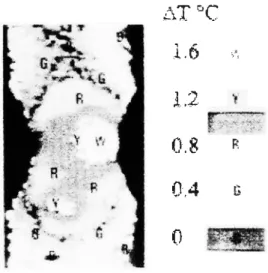
Infrared thermography readily depicts intrinsic dissipation localization announcing quite different mechanisms of damage preceding concrete failure. The different phases of heat dissipation, operating during an unstable failure, are readily described by heat patterns. When defects or weakness zones are present on the specimen, infrared observations evidence the progressive mechanism of defect coalescence (Figure 2). The rate of heat generation at the hottest location is used to detect the threshold of the failure process if compared with the traditional stress-strain curve. These results have been readily extended to rock materials10
3.4. Short-Time Evaluation of Fatigue Limit of Plain Concrete
In accordance with the coupled thermomechanical equation, the analysis of thermal images consists in isolating the intrinsic dissipation from thermal noises by simply subtracting the thermal image at reference time from the thermal image at 1000 load cycles. Computer aid thermography software allowed the data reduction of the thermal images using the function subtraction of images. The resulting image is a subtracted image showing the temperature change between two compared images, obtained under nearly identical test conditions. This image processing provided quantitative values of intrinsic dissipation.
This procedure is applied for each load step. The manifestation of the fatigue damage mechanism is revealed by a break of the intrinsic dissipation regime. The starting load level must be chosen below the fatigue limit. It significantly depends upon concrete characteristics. For example, we started the test at a stress level of about 20% of failure nominal stress, then 30%, 40%, etc. This is continued until temperature rise reaches some Celsius degrees. For each load step, an averaging treatment (among 4, 8, 16 or 32 thermogrammes) provides more stable thermal images.
Experimental results are summarized in Figure 3 that illustrates how the fatigue limit is determined using a graphical procedure. The threshold of critical thermal dissipation is roughly the same for different chosen number of load cycles. It roughly corresponds to the value deduced from standard procedures. These experiments have shown that the infrared thermographic technique can provide the fatigue limit of concrete within a few hours instead of several months when using for instance the traditional standard staircase method. These results are consistent with those obtained on concrete prisms
t
100 HzFigure I. The concrete specimen is subJected to a given static compression superimposed bv a vibratory compressive excitation
(frequency= 100Hz)
High strength concrete (R: = 43 MPa) in use in oil offshore concrete structures (North Sea)
c 3.5 Q
-.;:3
�T
oc
•�
.e-2.5
1;'-lFatigue Limit
.�
2
•Q
'
u1.5
·-= 1
�
• ·- •l::
0.5
I • •alae
c • • •- 0
0
0.2
0.4
0.6
0.8
1.0
Normalized Stress
Figure 3. The fatigue limit of the concrete specimen under compressive loading is graphically determined bv a drastic change
of the dissipative regime.
�T
'='C
1.6
.. ,,l '""
..•
.?·�-0.8
ROA
(;0
Figure 2. Infrared thermograph of a concrete specimen under vibratO!"'.' compressive excitation ( OJ>:l < alar-; <' 0 XX) W cakncss zones arc readily detected by heat patterns after 7.000 load cvclcs
(0 2 oc for each color hue)
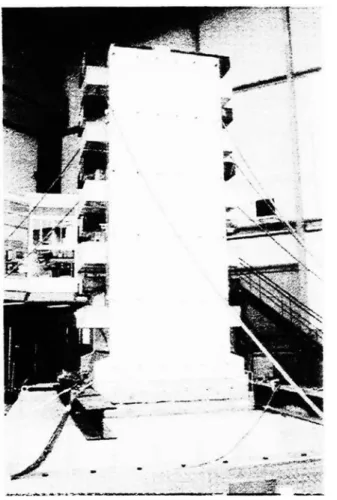
Figure 4. Expcnmental full scale concrete structure under a seismic tvpc loadmg
subjected to compressive fatigue testing21. This so determined stress limit could also be understood as a threshold of acceptable damage for plain concrete under compressive loading.
3.5. Infrared Thermographic Scanning of an Full-Scale Earthquake Resistant Concrete Structure
The damaged areas are located and highlighted by heat patterns. These results support and validate the assumptions to be taken into consideration in numerical procedures for stability and integrity assessment of concrete structures. The phenomenological behavior in consideration is therefore the standard of reference, allowing the use of the methods and results of continuum mechanics for analyzing and modeling their engineering performance. Information about the location and significance of structural defects as a basis for maintenance decisions, including the extreme case of removal from service, can be obtained through inspection and nondestructive evaluation.
The proposed infrared thermographic procedure involves careful examination of areas where defects are most likely to occur. Analyzing the structure and the service histories of similar structures in similar environments can identify the critical areas. The application of infrared scanning to inspection of concrete structure relies on the fact that the energy is dissipated during the process of accumulative damage when internal cracks or flaws develop. Figure 4 presents an experimental reinforced concrete building frame, intended for earthquake resistance studies. The most severe likely earthquake can be survived if the members are sufficiently ductile to absorb and dissipate seismic energy by inelastic deformations with little decrease in strength.
Under seismic-like loading, simulated by a rotating mass exciter placed on the top of the building, plastic hinges form progressively at the column bases where heat dissipation can be observed using infrared thermography as a function of the number of load cycles (Figures 5 and 6).
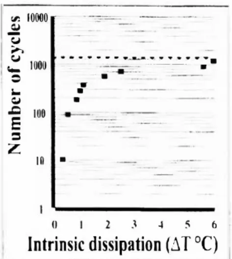
Computer aid thermography software allows the data reduction of the thermal images using the function subtraction of images and shows the progressive evolution of heat dissipation at a column base before crack line becomes visible. The resulting image is a subtracted image showing the temperature change between the reference time and after N load cycles (Figure 7). This image processing provided quantitative values of intrinsic dissipation corresponding to different numbers of load cycles. Obtained results after 270 load cycles (Figure 8) and after 360 load cycles (Figure 9) lead to a (log N - intrinsic dissipation) plot (Figure 10) that allows evaluation of fatigue lifetime of a column base of the experimental reinforced concrete structure subject to seismic-type loading.
The above data processing (heat image subtraction) applied for the overall structure provides useful information about localization of dissipation or damageable zones (Figure 1 1 ).
3.6. Infrared Observations of Energy Dissipation on Concrete Structures Subjected to Shaking Table Loading
Load bearing walls in reinforced concrete structures are of common use in France. Within the framework of the ECOEST2 (European Consortium of Earthquake Shaking Tables) and ICONS (Innovative Seismic Design New and Existing Structures, Topic 5 Shear wall structures) research project supported by the European Commission, two large-scale specimens (36 tons) representing 1/3rd scaled five-story buildings (so-called CAMUS III and CAMUS IV) have been tested under dynamic seismic-like loading on the major shaking table Azalee at CEA Saclay. The loading input signal is the so called Nice artificial accelerogram (far-field earthquake) characterized by its PGA (peak ground acceleration) values. These performed mock-up tests aim to demonstrate the major influence of boundary conditions at the base of the model, and the feasibility of optimizing low ratio and adequate distribution of reinforcements in order to obtain multi-cracking zones (multi-fuse concept) in opposition with the traditional pseudo plastic hinge localized at the base of a RIC wall (mono-fuse concept).
3.6.1 CAMUS ill highlighting the effects of reinforcement ratios
The CAMUS III specimen, composed of two lightly reinforced walls anchored to the shaking table, is designed as recommended Eurocode 8 allowing a plastic hinge at the base. Special attention has been paid on the influence of different reinforcement ratios and boundary conditions19 During the performed tests, CAMUS III mock-up suffered from high damage levels. Its behavior was mostly conditioned by its flexural bending. Examination after tests evidenced failure of steel reinforcements (Figure 12).
In this case, the dissipation mechanism caused by plasticity of steel reinforcements can be considered as an internal parameter so that the equation ( 1) has to be completed with two supplementary terms representing the cross coupling effects6, the former is caused by the dependence of the stress tensor on temperature (reversible) while the latter is induced
Figure 5. Thermal image of a column base of the reinforced concrete structure subjected to seismic tvpe loading at reference
time.
Figure 7. Intrinsic dissipation due toN load cvcles (Fi.r,'1lfe 6
subtracted by Figure 5)
y R BR
Figure<) Intrinsic dissipation due toN = �60 load cycles.
Figure fl. Thermal image of a column base of thc remforced concrete structure subjected to seismic type loading after N C\cles
of loading y G R BR G
Figure X Intrinsic dissipatiOn due to N = 270 load cycles
"' 10000 <lJ -� ... � ._ 1000 = -<lJ ,Q 100 E ::s z . - .. .. .. - - ._ ... .._ ... .. .. .. . -... . . • • -��:.-. --- . . . - ---10 • -0 2 J � � 6
Intrinsic dissipation (�
T
0C)
Figure I 0 Fatigue lifetime evaluation of a column base of the remforced concrete structure subJected to seismic type loadmg
Thermal image after excitation Thermal image before excitation l.ocalization of dissipation zones
Figure II. Subtraction between thermal images after and before excitation e\·idences the locali�:ation of dissipation or damaged zones .
....
�·
\..
Figure 12. CAMUS Ill mock-up on the shaking table of CEA Sacla\.
Heat image of CAMUS Ill
3 minutes after testing at peak ground acceleration
PGA � O.Xg
Heat Image of CAMUS Ill
3 mmutes after testing at peak ground acceleration
PGA � O.X."g
Figure l 3 Infrared thermographic detection of dissipation caused bY plastic1tv of steel reinforcements
Temperature changes arc giYen in °('
by the same dependence of the generalized force conjugates to the internal state vector (irreversible). This phenomenon appeared on the concrete surface with a delay depending on the depth of reinforcements. Thus infrared thermography readily evidenced and localized, on the scanned wall surface, the plasticity of steel reinforcements with a delay due to heat conduction characteristics of concrete (Figure 13).
3.6.2 CAMUS IV highlighting the effects of boundary conditions
The CAMUS IV specimen, composed of two lightly reinforced walls, was designed according to PS92 recommendations1 and simply rested on a 40 em thick sand layer (Figure 14). This test aimed to reproduce the phenomena of uplift and the fact that such a non-linear phenomenon was capable of isolating the structure from ground-borne excitation. In this case it is expected that soft boundary conditions will determine the seismic behavior of structural walls.
As in the above case, infrared thermography evidenced friction between steel reinforcements and concrete matrix with a delay necessitated by heat conduction through the concrete layer (Figure 15).
3. 7 Dissipative Mechanisms and their Range of Temperature Changes
Experimental results showed that the discrimination of the involved dissipative mechanisms is very delicate. Fortunately this work, originally intended to validate diverse different dissipative mechanisms, provided the following interesting discriminative characteristics of temperature changes (Table I).
L__
Dissipative mechanisms Range of temperature changes Time delayPlasticity of concrete under compression Up to 10 °Celsius In real time
Plasticity of steel reinforcements Some degrees oc Some minutes of delay
Slippage between steel reinforcements and concrete matrix Tenths of degrees °C Tens minutes of delay
Table I. Magnitude order of temperature change. 4. CONCLUDING REMARKS
This work has demonstrated that the dissipativity of the tested materials under loading is a highly sensitive and accurate
manifestation of damage.
Owing to the thermomechanical coupling, infrared thermography provides a nondestructive, non-contact and real-time test to observe the physical process of concrete degradation and to detect the occurrence of its intrinsic dissipation. Thus it readily provides a measure of the material damage and permits to define a limit of acceptable damage or fatigue limit of concrete under load beyond which the material is susceptible to failure. It should be pointed out that the inelastic strain due to compressive loading provides information only on the current geometry while the internal state variables provide information on the internal state and on the micro-structural defects.
The method allows not only qualitative work such as finding flaws, defects or weakness zones, but also quantitative analysis of the effects of flaws and defects on strength and durability of concrete structural components. This useful and promising technique offers an accurate illustration of crack initiation, and readily detects the onset of its unstable propagation through the material and/or flaw coalescence when cyclic loading generates increasing irreversible microcracking.
The main interest of this energy approach is to unit)· microscopic and macroscopic test data. The parameter intrinsic dissipation under consideration is a scalar quantity, easy to evaluate with accuracy. Subsequently it may suggest multiaxial design criteria, highly relevant for full scale testing on engineering structures.
Mechanical test data generated under non-cyclic conditions are insufficient to provide a comprehensive insight into the damage development in brittle concrete under cyclic loading. Design procedures ignoring fatigue phenomena may be seriously flawed, if the concrete structures concerned are loaded cyclically.
5. REFERENCES
1. AFNOR, "Regles PS applicables aux bdtiments, dites Regles PS92," Norme NF PI DTURegles PS92, 1995.
2. A Alliche and D. Franvois, "Fatigue damage of concrete," Fracture of concrete and rock, SEM!RILEM Int. Conf., Houston, Texas, June 1987, ed. by S.P. Shah, S.E. Swartz, Springer-Verlag, pp. 88-95, 1987.
Figure 14. This figure highlights the dissipation mechanism due to plasticitY of steel rcmforccments.
Input excitation = far-field earthquake (Nice artificial accelerogram)
Figure 15. CAMUS IV mock-up resting on a fine sand laYer on the shaking table of CEA Saclay.
=>
=>
Ileal changes arc giYcn in °(
Heat image taken (, minutes after seismic test at PGA = l.lg dunng 30 sec
Heat image taken I 0 minutes after seismic test at
PGA - I I g during 30 sec
Figure I(, Infrared thermographic detection of dissipation caused bY shppagc of steel reinforcements embedded m the concrete matm;
3. E. Cadoni, "Experimental study on concrete fatigue by means of pull-out test," Fatigue '96, Proc. Vlth Int. Fatigue Congress, m, pp. 1621-1626, 1996.
4. An. Carpinteri, "Fatigue crack growth in reinforced concrete," Micromechanics of failure of quasi-brittle materials, ed. by S.P. Shah, S.E. Swartz and M.L. Wang, Elsevier, pp. 541-548, 1990.
5. H.A.W. Cornelissen, Fatigue failure of concrete in tension, HERON, 29, No. 4, 1984.
6. M.K. Duszek and P. Perzyna, "The localization of plastic deformation in thermoplastic solids," Int. J. Solids Structures,
Great Britain, 27, N° 11 pp. 1419-1443, 1991.
7. K. Izuno and T. Ohkawa, "Quantification of repair effect for RC members using inelastic earthquake response analysis," Earthquake Engineering, lOth World Conj, Balkema, Rotterdam, 9, pp. 5221-5226, 1992.
8. M.P. Luong, "Infrared observation of failure processes in plain concrete," Durability of Building Materials and Component, 4 DBMC November 1987, Singapore, Pergamon, 2, pp. 870-878, 1987.
9. M.P. Luong, "Infrared thermovision of damage processes in concrete and rock," Engineering Fracture Mechanics, 35,
No. 1-2-3, pp. 127-135, 1990.
10. M.P. Luong, "Infrared thermographic observations of rock failure," Comprehensive Rock Engineering Principles, Practice & Projects, 4, Chap. 26, Pergamon, pp. 715-730, 1993a.
11. M.P. Luong, "Nondestructive analysis of microcracking in concrete," Int. Conj Nondestructive Testing of Concrete in the Infrastructure, Proc. SEM, Dearborn, pp. 199-217, 1993b.
12. M.P. Luong, "Infrared thermographic scanning of fatigue in metals," Nuclear Engineering and Design, Elsevier, 158
pp. 363-376, 1995.
13. M.P. Luong, "Infrared thermography of fatigue behavior of concrete under compression," 2nd Int. Conj Nondestructive Testing of Concrete in the Infrastructure, Proc. SEM, Nashville, pp. 167-176, 1996.
14. M.P. Luong, "Infrared thermography of macrostructural aspects of thermoplasticity," Micro- and Macrostructural Aspects of Thermoplasticity, ed. by O.T. Bruhns & E. Stein, Kluwer Academic Publishers, Solid Mechanics and its applications, 62, pp. 437-446, 1999.
15. M.P. Luong and J.C. Eytard, "Infrared thermovision of dissipation in concrete and concrete works," Genie Parasismique et Reponse Dynamique des Ouvrages, AFPS, ISBN 2-911709-08-X, II, pp. 471-478, 1999.
16. S. Nakashima, "Mechanical characteristics of steel column-base connections repaired by concrete encasement,"
Earthquake Engineering, lOth World Conj Balkema, Rotterdam, 9, pp. 5131-5136, 1992.
17. C. Ouyang, E. Landis and S.P. Shah, "Damage assessment in concrete using quantitative acoustic emission," J. Engineering Mechanics, 117, No. 11, pp. 2681-2698, 1991.
18. E. Papa, "A damage model for concrete subjected to fatigue loading," Eur. J. Mech., A/Solids, 12, No. 3, pp. 429-440, 1993.
19. J.C. Queval, D. Combescure, T. Chaudat and P. Sollogoub, "Seismic behaviour of reinforced concrete structural walls,"
Genie Parasismique et Reponse Dynamique des Ouvrages, AFPS, ISBN 2-911709-08-X, II, pp. 589-596, 1999. 20. G.S. Robinson, "Behavior of concrete in biaxial compression," J. Structural Div., ASCE, 93, pp. 71-86, 1967.
2 1. P.R. Sparks and J.B. Menzies, "The effect of rate of loading upon the static and fatigue strengths of plain concrete in compression," Mag. Concrete Res., 25, No. 83, pp. 73-80, 1973.
22. P. Stroeven, "Mechanisms of damage evolution in low-cycle compression fatigue of concrete," Fatigue '96, Proc. Vlth Int. Fatigue Congress, III, pp. 1615-1620, 1996.
23. S. Suresh, "Fatigue crack growth in cementitious solids under cyclic compression: theory and experiments," Fracture of concrete and rock, ed. by S.P. Shah, S.E. Swartz, B. Barr, Elsevier, pp. 162-172, 1989.
24. R. Valluvan, M.E. Kreger and J.O. Jirsa, "Strengthening of column splices in infilled shear walls," Earthquake Engineering, lOth World Conj, Balkema, Rotterdam. 9, pp. 5121-5126, 1992.
25. G.W.D. Vile, "The strength of concrete under short-term static biaxial stress," Int. Conj Structure of Concrete, Cement and Concrete Association, pp. 131-145, 1968.
26. B.S. Zhang, Z.H. Zhu and K.R. Wu, "Fatigue rupture of plain concrete analysed by fracture mechanics," Fracture of concrete and rock, SEMIRILEM Int. Conf., Houston, Texas, ed. by S.P. Shah, S.E. Swartz, Springer-Verlag, pp. 58-63, June 1987.
27. B.S. Zhang and D.V. Phillips, "Fatigue life of plain concrete under stress reversal," Fracture of concrete and rock, Ed. by S.P. Shah, S.E. Swartz, B. Barr. Elsevier, pp. 183-192, 1989.
28. B.S. Zhang, D.V. Phillips and K.R. Wu, "Further research on fatigue properties of plain concrete," Magazine of Concrete Research 49, No. 180, pp. 241-252, September 1997.