HAL Id: hal-02901474
https://hal.archives-ouvertes.fr/hal-02901474
Submitted on 17 Jul 2020
HAL is a multi-disciplinary open access
archive for the deposit and dissemination of
sci-entific research documents, whether they are
pub-lished or not. The documents may come from
teaching and research institutions in France or
abroad, or from public or private research centers.
L’archive ouverte pluridisciplinaire HAL, est
destinée au dépôt et à la diffusion de documents
scientifiques de niveau recherche, publiés ou non,
émanant des établissements d’enseignement et de
recherche français ou étrangers, des laboratoires
publics ou privés.
Consolidation of Carbon/Poly-Ether-Ketone-Ketone
Prepreg Laminate
Florence Saffar, Camille Sonnenfeld, Pierre Beauchene, Chung Hae Park
To cite this version:
Florence Saffar, Camille Sonnenfeld, Pierre Beauchene, Chung Hae Park. In-situ Monitoring of
the Out-Of-Autoclave Consolidation of Carbon/Poly-Ether-Ketone-Ketone Prepreg Laminate.
Fron-tiers in Materials.
Computational Materials Science section, Frontiers, 2020, 7 (195), pp.1-12.
doi: 10.3389/fmats.2020.00195
Edited by: Maria Chiara Bignozzi, University of Bologna, Italy Reviewed by: Liqing Wei, United States Forest Service (USDA), United States Veronique Michaud, École Polytechnique Fédérale de Lausanne, Switzerland *Correspondence: Florence Saffar florence.saffar@onera.fr
Specialty section: This article was submitted to Polymeric and Composite Materials, a section of the journal Frontiers in Materials Received:29 March 2020 Accepted:25 May 2020 Published:25 June 2020 Citation: Saffar F, Sonnenfeld C, Beauchêne P and Park CH (2020) In-situ Monitoring of the Out-Of-Autoclave Consolidation of Carbon/Poly-Ether-Ketone-Ketone Prepreg Laminate. Front. Mater. 7:195. doi: 10.3389/fmats.2020.00195
In-situ
Monitoring of the
Out-Of-Autoclave Consolidation of
Carbon/Poly-Ether-Ketone-Ketone
Prepreg Laminate
Florence Saffar1,2,3*, Camille Sonnenfeld1, Pierre Beauchêne1and Chung Hae Park2,3
1DMAS, ONERA, Université Paris Saclay, Châtillon, France,2Technology of Polymers and Composites & Mechanical
Engineering Department, IMT Lille Douai, Institut Mines-Télécom, Douai, France,3Université de Lille, Lille, France
The main objectives of this article were to examine the feasibility of high quality laminate (carbon PEKK—Poly-Ether-Ketone-Ketone) manufacturing under low pressure and to analyze the principal phenomena governing the consolidation quality. The quality of laminate was evaluated in terms of the interlaminar shear strength measured by short-beam shear test and the residual voids observed by micrographic images. This work underlined the possibility to obtain a good interlaminar consolidation quality, i.e., interlaminar shear strength of 100 MPa under a low pressure of 7.0 × 10⁴ Pa
even for prepregs which were not designed for out-of-autoclave processes. To better understand the interlaminar consolidation phenomena, we developed an experimental set-up for the in-situ monitoring of the laminate consolidation to measure the change of laminate thickness and the temperature gradient in the thickness direction during the manufacturing process. In particular, we identified two major phenomena, the establishment of intimate contact between the adjacent layers at the glass transition temperature and the molten matrix flow at the melting temperature. The assumption on the intimate contact establishment at the glass transition temperature was confirmed by the heat transfer simulation considering the change of thermal contact resistance at the interlaminar interface.
Keywords: polymer-matrix-composites (PMCs), interfacial strength, thermal properties, out-of-autoclave (OOA) consolidation, in-situ monitoring
INTRODUCTION
In the aircraft design and manufacturing, thermoplastic composites have many technical advantages over carbon/epoxy composites, such as high impact resistance, a short process cycle time, favorable storage conditions, and ease of patch repair. Among a wide spectrum of thermoplastic matrices for high performance composites are Poly-Aryl-Ether-Ketone (PAEK) matrices which have attracted great attention owing to high environmental resistance at elevated temperature. For example, unidirectional carbon fiber reinforced Poly-Ether-Ether-Ketone (PEEK) prepreg is a representative thermoplastic composite material used in the aircraft design (Bishop, 1985; Carlile et al., 1989; Denault and Dumouchel, 1998; El Kadi and Denault, 2001). Recently, more attention is being paid to Poly-Ether-Ketone-Ketone (PEKK) as a promising matrix material for
carbon fiber reinforced composites (Chang, 1988). PEKK has a higher glass transition temperature (155◦C) than PEEK (145◦C)
and offers a better high temperature resistance, whereas it has a similar melting temperature (335–340◦C) which leads to
almost the same manufacturing condition as PEEK. In spite of its advantages, the data on the carbon/PEKK consolidation is seldom found in the literature, however, whereas the characterization of carbon/PEEK prepreg systems has been extensively reported (Blundell et al., 1989; Yang and Colton, 1995; Phillips et al., 1997; Ageorges et al., 1998; Gao and Kim, 2000, 2001; Wang et al., 2001; Stokes-Griffin and Compston, 2016a; Talbott et al., 2016). Only a small number of articles about the degradation and isothermal crystallization of PEKK have been published by Choupin et al. and other authors (Hsiao et al., 1991; Krishnaswamy and Kalika, 1996; Choupin, 2017; Tadini et al., 2017; Choupin et al., 2018; Li and Strachan, 2019).
Moreover, a critical drawback in the use of such materials is the high manufacturing cost. In general, the price of those materials is very high. To reduce the labor cost due to the manual lay-up, automated tape placement (ATP) is widely considered (Khan et al., 2010; Comer et al., 2015; Stokes-Griffin and Compston, 2016a,b). Nevertheless, the high consolidation quality cannot be achieved only by ATP and a post-consolidation process is required. For this post-consolidation step, an expensive manufacturing equipment such as autoclave is generally used because high temperature and pressure are needed to consolidate laminates. Indeed, all the commercial grades of carbon/PEKK prepreg available in the current market are designed for the autoclave manufacturing.
Nowadays, there is a growing interest in out-of-autoclave consolidation processes where low compaction pressure is employed to reduce the manufacturing cost (Witik et al., 2012; Centea et al., 2015). For example, laminates can be consolidated under vacuum condition in a heated oven.
About the high pressure consolidation of thermoplastic composites, different phenomena have already been identified such as intimate contact, autohesion, and crystallization.
The phenomenon of intimate contact has been described by different models. In the literature, the principal mechanism of the intimate contact establishment has been assumed to be the flattening of surface roughness which has been modeled by the squeeze flow of the material under compaction pressure (Lee and Springer, 1987; Loos and Dara, 1987; Mantell and Springer, 1992; Butler et al., 1998; Yang and Pitchumani, 2001). In the early work, the main focus was on the description of the geometric pattern on the rough surface of prepreg. For example, Dara and Loos proposed a model where the surface roughness of the prepreg was represented by a series of rectangles with different dimensions (Loos and Dara, 1987). Lee and Springer simplified this model by representing the prepreg surface roughness by a series of rectangles with the same dimensions (Lee and Springer, 1987). Nevertheless, the limits of this model have also been underlined. Butler et al., and Yang and Pitchumani explained that the identification of the geometric parameters in the models was very complex (Butler et al., 1998; Yang and Pitchumani, 2001). The results of profilometric and micrographic studies showed that the prepreg surface roughness could not necessarily
be described by rectangles. Butler et al. highlighted that according to the geometric parameters, the time for the intimate contact establishment could vary between 1 and 105 s (Butler et al.,
1998). Hence, Yang and Pitchumani introduced Cantor fractals to represent the surface roughness of prepreg ply (Yang and Pitchumani, 2001). By this method, the estimation of intimate contact establishment time could be close to a real value. Yet, the complexity to determine the geometric parameters still remains as a critical issue to address in this approach.
In another approach, the evolution of the intimate contact during the consolidation was assessed by the change of the thermal contact resistance between the adjacent plies of a laminate. To monitor the evolution of this thermal contact resistance, Schaefer et al. installed thermocouples between the adjacent layers in the middle of composite laminate (Schaefer et al., 2016, 2017). With the temperature values measured by the thermocouples, the thermal diffusivities of initial prepreg and of final consolidated laminate were estimated. Subsequently, they determined the thermal contact resistance at the interface between the adjacent layers and found that it decreased during the consolidation process. The relation between the thermal contact resistance and the intimate contact has also been studied by Levy et al. (2014) and Cassidy and Monaghan (1994). It should be noted that in all the aforementioned works, the composite material was considered to be viscous fluid and the intimate contact was assumed to take place at high temperature (i.e., around the melting point of the matrix) and under high compaction pressure (i.e., over 3.0 × 10⁵ Pa). Moreover, all
the works have focused on the PEEK, Polyimide, and PIXA-M matrix composites, whereas PEKK matrix composites have not been investigated (Lee and Springer, 1987; Butler et al., 1998; Yang and Pitchumani, 2001). Finally, the intimate contact phenomenon of carbon fibers/PEKK laminates began to be investigated in a recent work by Çelik et al. (2020). This last study focuses on the intimate contact phenomenon during laser assisted automated fiber placement manufacturing, and so under high pressure conditions.
Therefore, the main subject of this paper is the low pressure consolidation of carbon fibers/PEKK laminates. In particular, the influence of pressure level on the consolidation is experimentally investigated. Moreover, an in-situ monitoring set-up to study the consolidation phenomena in terms of the temperature differential in the thickness direction and the change of the total thickness of laminates is presented. Finally, thermal modeling of the intimate contact phenomenon under low pressure is proposed.
EXPERIMENTAL METHODS AND
NUMERICAL SIMULATION
Material
We used unidirectional carbon fiber reinforced PEKK prepreg. The weight fraction of fibers was 66 %, the areal weight was 145 g/m2 and the thickness of a single ply before the
consolidation was 0.15 mm. A microscopic image of the prepreg ply is presented in Figure 1. The prepreg was placed in an oven
at 120◦C for 80 min before the consolidation process to dry
the samples.
Thermal Expansion Characterization
The thermal expansion of the prepreg in the thickness direction was evaluated by dilatometer (TGA-TDA Setsys Evolution 16/18). The chosen temperature cycle was a 5 K/min heating rate from 40 to 300◦C and an inert gas (argon) was used in order
to obtain the conditions close to the vacuum manufacturing conditions. Tested samples were laminates with a thickness of 4.3mm consolidated using a press. The prepregs were placed in an oven at 120◦C for 80 min before the measurement of thermal
expansion coefficient.
Two Set-Ups for Out-Of-Autoclave
Manufacturing
Two different heating methods were employed for out-of-autoclave consolidation, namely, oven and heating plate.
FIGURE 1 | Microscopic image of the prepreg ply.
Oven Heating
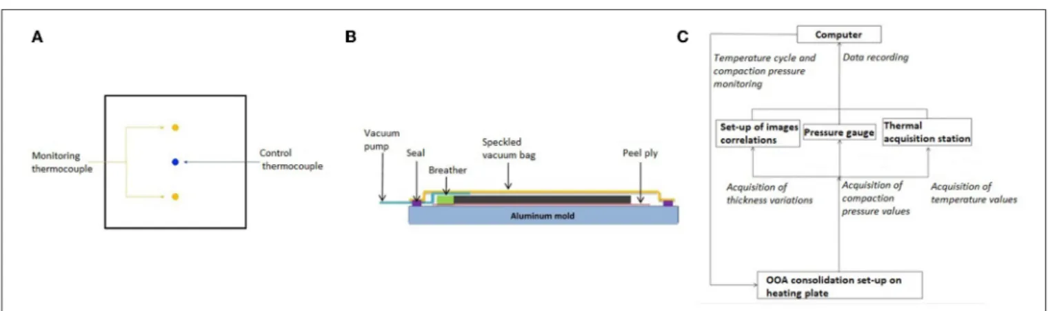
In order to study the feasibility of out-of-autoclave manufacturing, laminate consolidation in a heated oven was used. Using this experimental set-up, only the temperature was measured whereas the thickness of laminate was not monitored. A laminate lay-up of 16 UD plies was chosen. The planar dimensions of the laminates were 115 × 115 mm2. Three
thermocouples of K type were installed on the planar surfaces of laminate to monitor the temperature evolution as shown in
Figure 2A. Because the laminate stack was heated in an oven, relatively uniform heating of laminates could be obtained. The temperature cycle of the oven was controlled by Eurotherm system. The vacuum pressure applied to the laminate stack was controlled and recorded by a pressure gauge (Pfeiffer APR250). One-Side Heating Plate
The second method which has been developed is a heating plate set-up in order to monitor both the temperature difference and the laminate thickness change. A stack of 16 UD prepreg plies with planar dimensions of 60 × 60 mm2was placed on a stainless
steel plate which was heated. The prepreg stack was subsequently covered by a speckled vacuum bag as shown in Figure 2B. Two thermocouples of K type with a diameter of 0.25 mm were installed beneath and on the laminate. It should be noted that the laminate was heated only from the bottom side which induced a non-uniform temperature distribution through the thickness direction. As previously done for the oven heating method, the temperature cycle of the stainless steel plate was controlled by Eurotherm system and the vacuum pressure was controlled and recorded by a pressure gauge.
To monitor the change of the laminate thickness during the consolidation, speckles were applied on the upper face of the vacuum bag and two optical cameras (AVT Pike-421, 4/80 lens and 41 mm extension ring) were placed 1,000 mm above the laminate stack. The angle between the two cameras was around 33◦to measure the change of the out-of-plane displacement. The
data acquisition interval was 30 s. Vis-Snap 8 was used as a data acquisition system and the data processing was performed by Vic-3D. For each time step, the mean value of laminate thickness
FIGURE 2 | In-situ monitoring system for out-of-autoclave consolidation of thermoplastic composites. (A) Scheme of thermocouples monitoring for oven manufacturing. (B) Schematic of prepreg lay-up. (C) Schematic diagram of in-situ monitoring system.
was calculated from around 35 data on the sampling surface of 5 × 5 cm2 which was located in the center of the laminate
surface of 6 × 6 cm2in order to avoid the edges effects. During
the consolidation, the pressure, the temperatures at the top and at the bottom of the laminate and the laminate thickness were recorded. The whole in-situ monitoring system is represented by a schematic drawing in Figure 2C.
Manufacturing Conditions
Temperature Cycle
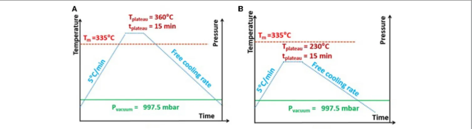
Two different temperature cycles were applied in the heating plate method, to investigate the influence of temperature on the interlaminar consolidation.
In the first case, a classic temperature cycle was used for manufacturing with the heating plate. A prepreg stack was heated from room temperature at a heating rate of 5 K/min. Once the temperature reached 360◦C (=Melting temperature of
PEKK + 25◦C), this temperature was maintained for 15 min.
Then, the prepreg stack was cooled down at a free cooling rate (see Figure 3A).
To better understand the consolidation phenomena, another identical successive consolidation cycle was applied again on the laminate which had already been consolidated.
In the second case, a stack of prepreg which had not been consolidated was submitted to the peak temperature of 230◦C which was maintained for 15 min, while employing the
same heating and cooling rates (see Figure 3B), to observe the interlaminar microstructure of laminate consolidated at the intermediate temperature (i.e., 230◦C) between the glass
transition temperature (Tg) and the melting temperature (Tm).
Finally, for the manufacturing in an oven, the same temperature cycle as shown in Figure 3A was applied, while employing a different cooling rate of 5 K/min.
Vacuum Pressure
The compaction pressure applied on the prepreg stack was determined by the difference between the atmospheric pressure and the vacuum pressure. During the manufacturing cycles, a steady vacuum pressure was applied. The used reference value was −995 × 102 Pa. In order to determine the minimum
compaction pressure to obtain a good consolidation quality, different compaction pressure values (i.e., −995 × 102, −973
× 102, −915 × 102, −825 × 102,−740 × 102, −511 × 102, −253 × 102,−209 × 102, −185 × 102, −93 × 102, −24 × 102) were tested in the oven manufacturing method. Moreover, two different vacuum pressures (−995 × 102Pa, −325 × 102Pa) were used for heating plate method to better understand the influence of vacuum pressure on interlaminar consolidation phenomena.
Assessment of Consolidation Quality:
Interlaminar Shear Strength and Void
Content
Despite the drawbacks of interlaminar shear strength (ILSS) test related to the multiple failure modes which can occur for thermoplastic composites (Kadlec et al., 2014), ILSS test is widely accepted because the interlaminar shear strength of laminate is a representative parameter which is sensitive to interlaminar properties in shear, and in addition it is easy and fast to perform. Furthermore, their results are reproducible from a test to another and enough discriminating. Three rectangular specimens were cut from each laminate according to the same orientation in the laminate to conduct short-beam shear three-point bending. The dimensions of the specimens were 25 × 12 × 2.35 mm3. For the
three-point short-beam shear test, the radius of the loading pin was 5 mm and the radius of the two supporting pins was 2 mm. The distance between the two supporting pins was 12 mm and the displacement speed of the loading pin was 0.5 mm/min. The tests were performed on Zwick/Roell Z010 with a load cell of 10 kN.
Reference laminate samples were fabricated by the compression molding with a high compaction pressure (i.e., 10 ×105Pa), while applying the same temperature cycle as shown in Figure 3A. The corresponding ILSS value was regarded as the reference ILSS of the present prepreg samples.
The void content was evaluated by image analysis. The transverse cross-section of laminates was observed using an optical microscope and the void content was determined by thresholding method on (Image J software, 2020). The observations were made at the zone around the interlaminar interfaces and the observation window size was 1,740 × 60 µm2.
TABLE 1 | Thermal properties of the prepreg.
T = 50◦C T = 100◦C T = 150◦C T = 200◦C T = 250◦C T = 300◦C
Cp (J/g.◦C) 0.6681 0.8481 1.025 1.269 1.454 1.639
δ(m2/s) 4.28 × 10⁻⁷ 3.99 × 10⁻⁷ 3.71 × 10⁻⁷ 3.24 × 10⁻⁷ 3.06 × 10⁻⁷ 2.80 × 10⁻⁷
Characterization of the Thermal Properties
and Numerical Simulation of Heat Transfer
One dimensional finite element model was used for the numerical simulation of heat transfer during the heating plate manufacturing method. The computational domain for heat conduction was composed of 16 layers of composite prepreg with a thickness of 0.15 mm and 15 interlaminar interface layers with a thickness of 8 µm which corresponded to the mean height of the prepreg surface roughness. For the heat transfer simulation, the heat transfer module of COMSOL was used. As the boundary conditions, a convective heat transfer coefficient of 15 W·m−2·K−1 was applied on the top surface
and a preassigned temperature profile was given at the bottom surface. The density of prepreg was 1,400 kg/m3. The thermal diffusivity (δ) has been measured for temperatures between room temperature and 300◦C at every 50◦C by flash method on the
consolidated laminate with a thickness of 2.3 mm. Finally, the specific heat capacity (Cp) of prepreg was evaluated by DSC tests. All the material properties which were used in this model are summarized in Table 1. For the interface layers, the thermal properties were assumed to change, as the intimate contact was established according to the increase of temperature. The thermal conductivity of the interface layers was represented by a sigmoid temperature dependent function. This function was defined by four parameters, viz. the initial conductivity (kinit),
the final conductivity (kfin), the inflection temperature (Tr), and
the temperature range (dT) (see Figure 4). These four parameters were determined by an inverse identification using Levenberg-Marquardt method (Marquardt, 1963).
RESULTS AND DISCUSSION
In-situ
Monitoring Data: Temperature
Difference and Laminate Thickness
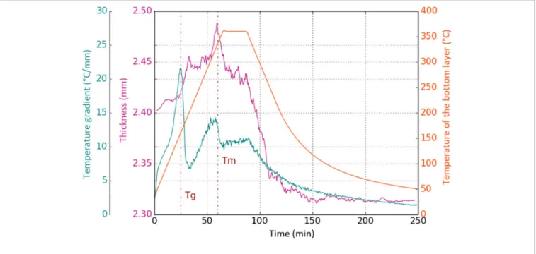
From the in-situ monitoring of thermoplastic laminates manufacturing on the heating plate, the data for the thickness of the laminate and the average temperature gradient through the thickness during the whole consolidation cycle were obtained.
Figure 5 shows the time-dependent change of the laminate thickness obtained by the two optical cameras and the change of the average temperature gradient.
The temperature gradient was greatly increased from “Tg−30◦C” and reached its maximum value when the temperature of the bottom layer was Tg(see Figure 5).
Afterwards, the temperature gradient dropped fast as the temperature increased further from Tg. At the same time,
an increase of the laminate thickness was observed as the temperature increased above Tg. Both the laminate thickness
and the temperature differential were decreased again around
FIGURE 4 | Evolution of thermal conductivity of interlaminar interfaces with temperature.
the melting temperature of the matrix, even if the temperature of the bottom layer continued to increase. We could verify the reproducibility of these observations from the repeated experiments under the same condition. This speculation can be verified by the successive consolidation experiment.
In Figure 6, the evolution of the temperature difference between top and bottom layers is shown during the two identical successive consolidation steps. We can see two sudden decreases of temperature difference at the glass transition temperature and the melting temperature, respectively, during the first consolidation. During the second consolidation of the same laminate, however, such sudden decrease of temperature is not observed at the glass transition temperature. Thus, we can assume that the intimate contact was totally established during the first consolidation and there was no more change of thermal contact resistance at the interlaminar interfaces during the second consolidation.
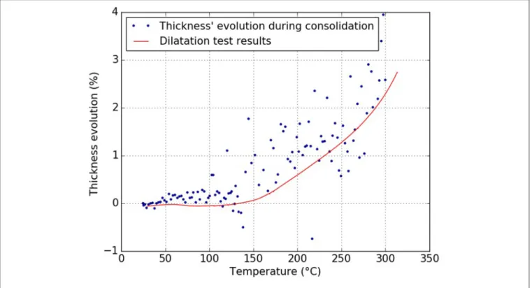
The change of the laminate thickness can be explained by the competition between the thermal expansion effect and the intimate contact establishment which tends to decrease the thickness due to the flattening of prepreg surface roughness. Until the melting temperature of the matrix, the increase of the laminate thickness according to the increase of temperature can be correlated with the coefficient of thermal expansion (CTE) in the thickness direction of laminate which had been experimentally measured (see Figure 7).
Conversely, it is assumed that the molten matrix flow at the interlaminar interfaces accounts for the decreases of the laminate
FIGURE 5 | Results of average temperature gradient and thickness against time.
FIGURE 6 | Result of temperature difference for two successive consolidation cycles.
thickness at the melting temperature. Thus, it can be assumed that the intimate contact is not totally complete between the glass transition temperature and the melting temperature, however and there are still some voids at the interlaminar interfaces. The perfect contact between adjacent layers is only obtained around the melting temperature (see Figure 8). Microscopic observations of laminates highlight a relatively low void content
which shows the establishment of intimate contact at the interlaminar interfaces (see Figure 9). The most of voids are concentrated at the three or four top interlaminar interfaces close to the vacuum bag and the approximate void content at these zones is 5%. At the other zones, it is not easy to identify the interfaces between two adjacent layers and the void content is lower than 2%. This difference between the upper
FIGURE 7 | Comparison between thermal expansion and laminate thickness results.
FIGURE 8 | Schematic of the interlaminar consolidation phenomena. (A) Below Tg. (B) At Tg(Establishment of intimate contact). (C) At Tm(Molten matrix flow).
and bottom zones in the laminate can be explained by the delay in the temperature rise due to one side heating from the bottom heating plate. The maximum temperature in the upper part near the vacuum bag just reached the melting temperature of the PEKK when that in the bottom part near the heating plate was sufficiently above the melting temperature. Thus, we can suppose that some portion of matrix in the upper layers was not sufficiently melted and therefore the matrix could not flow to fill the interlaminar gaps in these zones. Otherwise, voids could migrate from the bottom zone to the upper zone of the laminate because they might move along the negative temperature gradient according to the phenomenon described by
Lu et al. (2004).
Laminate Consolidated at the Low
Temperature
Figure 10shows a micrographic image of the laminate obtained by low temperature consolidation (i.e., 230◦C). Because the
laminate was consolidated above the glass transition temperature, the intimate contact began to be established even if it was not totally complete. The surface roughness was reduced and the adjacent layers became in contact with each other. Nevertheless,
FIGURE 9 | Micrographic image of laminate consolidated by one side heating plate.
there was still a high average content (e.g. ∼11%) of interlaminar voids. It was more difficult to assess the gradient of void content in the thickness direction in a partially consolidated laminate (consolidated at the low temperature, i.e., 230◦C) than in a fully
consolidated laminate (consolidate at the high temperature, i.e., 360◦C). It could be noticed only that the void content at the
interlaminar interfaces was higher at the outer layers (>10%) than at the middle layers (<6%) of the laminate.
The final laminate quality was also evaluated by ILSS tests. The interlaminar shear strength of the laminate consolidated at 230◦C
was around 1 MPa. We can conclude that the intimate contact establishment at the glass transition temperature is not enough to build the interlaminar bonding strength. Once the matrix temperature reaches at the melting temperature, the matrix is melted and flows to fill the small gaps between the adjacent layers (see Figure 8C). As the temperature rises further above the melting point, there is an interdiffusion of polymer molecules across the interlaminar interfaces to erase the interface between the adjacent layers which establishes the interlaminar bonding strength (see Figure 8D). Thus, the phenomena at the melting temperature, viz. molten matrix flow and molecule interdiffusion play the principal role in the laminate consolidation process.
It should be emphasized that the intimate contact begins to be established at a low temperature, viz. around the glass transition temperature, whereas in the literature it has been assumed to occur at a high temperature, i.e., around the melting temperature of the matrix. Hence, the initial surface roughness of prepreg ply is changed above the glass transition temperature, which improves the intimate contact between adjacent layers. This phenomenon can be correlated with the reduction of thermal contact resistance at the interlaminar interfaces. We can see in Figure 5 that the decrease of the average temperature gradient took place around the glass transition temperature. As the intimate contact is established, the heat conduction path is enlarged and the thermal resistance is decreased at the interlaminar interfaces.
Influence of Compaction Pressure
The influence of the compaction pressure on the interlaminar consolidation of laminate was investigated for both heating methods, i.e., heating plate and oven.
For the heating plate method, two levels of compaction pressure were tested, viz. 995 × 102 Pa and 325 × 102 Pa.
Figure 11presents the in-situ monitoring results of the evolution of the average temperature gradient, which is the temperature difference divided by the laminate thickness (Figure 11A) and the evolution of the laminate thickness (Figure 11B). It should be noticed that the laminate thickness was not uniform on the surface of the laminate. The final thickness of laminate was greater in the zones far from the pressure pump than near the pressure pump. This difference is assumed to be come from the non-uniform distribution of compaction pressure. Moreover, the standard deviation of the laminate thickness was increased with the decreasing of compaction pressure applied during the consolidation cycle. Thus, the maximum value for standard deviation was obtained for the compaction pressure of 325 × 102 Pa which is presented in Figure 11C.
The average temperature gradient and the laminate thickness were highly dependent on the compaction pressure. In the case of low compaction pressure (i.e., 325 × 102 Pa), there was no
remarkable change of the average temperature gradient and the laminate thickness at the glass transition temperature. Moreover,
it should be noted that the average temperature gradient at the plateau of peak temperature was the highest for the lowest value of compaction pressure (i.e., 325 × 102 Pa). This high average
temperature gradient implies a weak interlaminar consolidation because of the too low compaction pressure.
In the same manner, the result of the laminate thickness evolution shows that the lowest compaction pressure led to a higher laminate thickness during the whole consolidation cycle. This implies the presence of air layers at the interlaminar interfaces which are likely to swell during the heating phase. Finally, the sudden change of the average temperature gradient at the glass transition temperature is also related with the change of the thermal conductivity of the air layers at the interlaminar interfaces, which can be correlated with the compaction pressure according to Equation 1 adopted by Wu et al. (Cassidy and Monaghan, 1994). kair= k0 1 +7.6.10−5T PD (1) where kair is the thermal conductivity of air, ko is the thermal
conductivity of air at the room temperature and pressure, T is the temperature (in K), P is the air pressure and D is the air gap height.
When the compaction pressure was important, the pressure in vacuum bag was below 5.0 × 10² Pa and the corresponding
thermal conductivity of air was around 1 mW/(m·K). This low value increased the magnitude of the average temperature gradient. On the contrary, when the compaction pressure was around 325 × 102 Pa, the thermal conductivity of air in the vacuum bag and in the gaps at the interlaminar interfaces was around 25 mW/(m·K) at room temperature. The difference of the thermal conductivity between the prepreg plies and the interlaminar zones was not big enough to highlight the intimate contact phenomenon.
As a result, it has been found that thermoplastic laminates can be consolidated under low pressure (< 1.0 × 10⁵ Pa) and
that under these conditions the in-situ monitoring is helpful to improve the understanding of the interlaminar consolidation.
In the oven heating method, the temperature distribution is more uniform than in the heating plate method. Hence, the
FIGURE 11 | Compaction pressure influence on the consolidation phenomena. (A) Temperature gradient evolution. (B) Thickness evolution. (C) Maximal standard deviation of laminate thickness variations for 3.25 × 10⁴Pa.
influence from the non-uniform heating on the interlaminar consolidation can be minimized and eventually ruled out. The interlaminar consolidation quality was assessed by ILSS tests.
Figure 12 shows the results of the interlaminar shear strength of the laminates against the compaction pressure which was applied during the consolidation. The compaction pressure has a huge influence on the final consolidation quality of the material. The ILSS changes from 21 MPa to 107 MPa when the compaction pressure increases from25 × 102 Pa to 980
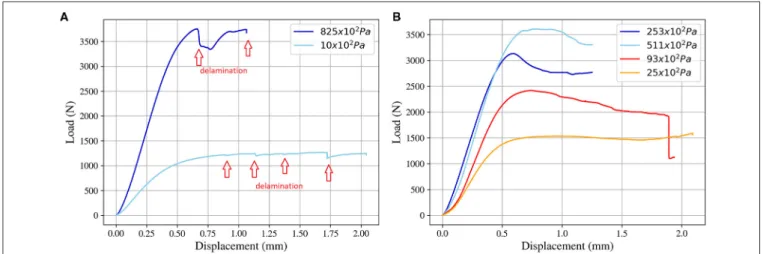
× 102 Pa. Moreover, above 700 × 102 Pa the ILSS values are superior to 100 MPa which is so close to the reference value, viz. 110 MPa (from the compression molded samples). The failure modes of the laminates were more complex to identify. Indeed, the delamination mostly occurred at very low compaction pressure (−10 × 102 Pa) whereas it could also take place for the laminates consolidated at−825 × 102 Pa (see
FIGURE 12 | Results of ILSS measurements for different compaction pressure levels in the heated oven (*: average thickness of the laminate in mm).
Figure 13A). However, this failure mode was relatively rarely observed. Most of samples showed large plastic deformation with or without a small drop of stress after the elastic region (see
Figure 13B) which can reveal the presence of crack propagation (van Rijswijk et al., 2009; Vieille et al., 2011; See et al., 2015; Obande et al., 2019). According to these results the failure mode cannot be directly related with the pressure level of the consolidation.
These results highlight that high interlaminar consolidation quality can be achieved by Out-Of-Autoclave (OOA) or Vacuum-Bag-Only (VBO) manufacturing techniques.
Heat Transfer Simulation Result
The four parameters of the sigmoid function for the thermal conductivity of interface layers (see Figure 4) have been identified. The temperature range (dT) was 22 K. The inflection temperature (Tr =440 K) corresponded to the glass transition temperature and the improvement of conductivity is associated with the matrix phase change. The initial conductivity (kinit) was
0.003 W·m−1·K−1 which corresponded to the air conductivity
under very low pressure (1–5 × 10² Pa). The final conductivity
(kfin) was 0.032 W·m−1·K−1 which was still lower than the
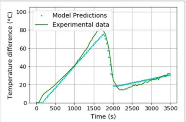
matrix conductivity, because the intimate contact was not complete under the melting point. Figure 14 presents the experimental result and the simulation result for the temperature evolution at the top layer during the consolidation process. We can see that the fast increase of the temperature at the top layer above the glass transition temperature was well-reproduced by the numerical simulation considering the change of thermal contact resistance at the interlaminar interfaces. As the amorphous zones of the matrix softened above the glass transition temperature, the surface roughness was deformed and flattened out to increase the contact area between the adjacent layers. Subsequently, the heat conduction path was enlarged and the thermal contact resistance was decreased. As a result, the heat transfer was enhanced and the temperature at the top layer was fast increased.
FIGURE 14 | Experimental and numerical results of the temperature at the top layer.
CONCLUSION
The OOA or VBO manufacturing of high performance thermoplastic composite laminate was investigated by in-situ monitoring method. Two kinds of experimental set-up were developed, viz. the oven heating method where more uniform heating could be obtained and the heating plate method coupled with the in-situ monitoring system. For this second set-up, carbon/PEKK prepreg laminates were fabricated by the one-side heating mold while the laminate thickness and the temperature differential along the thickness direction were monitored during the consolidation cycle. This method was very effective to produce laminates which were unaltered by the in-situ monitoring (no thermocouples placed inside the laminates) and to analyze the interlaminar consolidation phenomena during the manufacturing process.
Moreover, this work proved the feasibility to consolidate thermoplastic laminate with high interlaminar shear strength by VBO set-up, according to ILSS results and microscopic observations. A high ILSS value (around 100 MPa) can be reached for compaction pressure above700 × 102Pa.
Finally, from the in-situ monitoring experiments, the two major phenomena were identified. At the glass transition temperature of the matrix, the laminate thickness and the temperature differential are decreased. It is assumed that the amorphous zone of the matrix softens at the glass transition temperature and the surface roughness of prepreg can be flattened out to establish the intimate contact even under low compaction pressure, i.e., below1.00 × 105Pa. This establishment
of intimate contact reduces the thermal contact resistance at the interlaminar interfaces and subsequently decreases the temperature differential. In particular, it has been found that the intimate contact begins to be established at the glass transition temperature whereas, in the literature, it has been assumed to take place around the melting temperature. At the melting temperature, the matrix becomes totally in a molten state to flow into small gaps at the interlaminar interfaces and the polymer molecules can get across the interfaces to build the interlaminar bonding strength.
DATA AVAILABILITY STATEMENT
The raw data supporting the conclusions of this article will be made available by the authors, without undue reservation.
AUTHOR CONTRIBUTIONS
FS, CS, and PB contributed to the design of experimental works and realized them. All the authors contributed to the development of the model, the interpretation of the results, the statistical analysis, and contributed to conception of the study.
REFERENCES
Ageorges, C., Ye, L. Y., Mai, W., and Hou, M. (1998). Characteristics of resistance welding of lap shear coupons.: Part IConsolidation. Compos. Part Appl. Sci. Manuf. 29, 911–919. doi: 10.1016/S1359-835X(98)00023-2
Bishop, S. M. (1985). The mechanical performance and impact behaviour of carbon-fibre reinforced PEEK. Compos. Struct. 3, 295–318. doi: 10.1016/0263-8223(85)90059-5
Blundell, D. J., Crick, R. A., Fife, B., Peacock, J., Keller, A., and Waddon, A. (1989). Spherulitic morphology of the matrix of thermoplastic PEEK/carbon fibre aromatic polymer composites. J. Mater. Sci. 24, 2057–2064. doi: 10.1007/BF02385421
Butler, C. A., McCullough, R. L., Pitchumani, R., and Gillepsie, J. W. J. (1998). An analysis of mechanisms governing fusion bondinf of thermoplastic composites. J. Thermoplast. Compos. Mater. 11, 338–363. doi: 10.1177/089270579801100404 Carlile, D. R., Leach, D. C., Moore, D. R., and Zahlan, N. (1989). “Mechanical Properties of the Carbon Fiber/PEEK Composite APC-2/AS-4 for Structural Applications,” in Advances in Thermoplastic Matrix Composite Materials, ed. G. Newaz (West Conshohocken, PA: ASTM International), 199–212. doi: 10.1520/STP24603S
Cassidy, S. F., and Monaghan, P. F. (1994). Effect of contact resistances on the thermal conductivity of an unconsolidated fibre-reinforced thermoplastic prepreg stack, Compos. Manuf. 5, 225–230. doi: 10.1016/0956-7143(94)90137-6
Çelik, O., Peeters, D., Dransfeld, C., and Teuwen, J. (2020). Intimate contact development during laser assisted fiber placement: microstructure and effect of process parameters. Compos. Part Appl. Sci. Manuf. 134:105888. doi: 10.1016/j.compositesa.2020.105888
Centea, T., Grunenfelder, L. K., and Nutt, S. R. (2015). A review of out-of-autoclave prepregs – material properties, process phenomena, and manufacturing considerations. Compos. Part Appl. Sci. Manuf. 70, 132–154. doi: 10.1016/j.compositesa.2014.09.029
Chang, I. Y. (1988). PEKK as a new thermoplastic matrix for high-performance composites. Sampe Q U. S. 19.
Choupin, T. (2017). Mechanical Performances of PEKK Thermoplastic Composites Linked to Their Processing Parameters. Paris: Ecole Nationale Supérieure d’Arts et Métiers.
Choupin, T., Fayolle, B., Régnier, G., Paris, C., Cinquin, J., and Brul,é, B. (2018). A more reliable DSC-based methodology to study crystallization kinetics: Application to poly(ether ketone ketone) (PEKK) copolymers. Polymer 155, 109–115. doi: 10.1016/j.polymer.2018. 08.060
Comer, A. J., Ray, D., Obande, W. O., Jones, D., Lyons, J., Rosca, I., O’ Higgins, R. M., et al. (2015). Mechanical characterisation of carbon fibre–PEEK manufactured by laser-assisted automated-tape-placement and autoclave. Compos. Part Appl. Sci. Manuf. 69, 10–20. doi: 10.1016/j.compositesa.2014.10.003
Denault, J., and Dumouchel, M. (1998). Consolidation process of PEEK/carbon composite for aerospace applications. Adv. Perform. Mater. 5, 83–96. doi: 10.1023/A:1008638105370
El Kadi, H., and Denault, J. (2001). Effects of processing conditions on the mechanical behavior of carbon-fiber-reinforced PEEK. J. Thermoplast. Compos. Mater. 14, 34–53. doi: 10.1106/XDX9-U8K4-E0PM-70MX
Gao, L.-S., and Kim, K.-J. (2000). Cooling rate influences in carbon fibre/PEEK composites. Part 1. Crystallinity and interface adhesion. Compos. Part Appl. Sci. Manuf. 31, 517–530. doi: 10.1016/S1359-835X(00)00009-9
Gao, L.-S., and Kim, K-J. (2001). Cooling rate influences in carbon fibre/PEEK composites. Part II: interlaminar fracture toughness. Compos. Part Appl. Sci. Manuf. 32, 763–774. doi: 10.1016/S1359-835X(00)00188-3
Hsiao, B. S., Chang, I. Y., and Sauer, B. B. (1991). Isothermal crystallization kinetics of poly(ether ketone ketone) and its carbon-fibre-reinforced composites, Polymer 32, 2799–2805. doi: 10.1016/0032-3861(91)90111-U
Image J software (2020). Availabvle online at: https://imagej.nih.gov/ij/
Kadlec, M., Nováková, L., and RuŽek, R. (2014). An experimental investigation of factors considered for the short beam shear strength evaluation of carbon fiber–reinforced thermoplastic laminates. J. Test. Eval. 42, 581–592. doi: 10.1520/JTE20120043
Khan, M. A., Mitschang, P., and Schledjewski, R. (2010). Identification of some optimal parameters to achieve higher laminate quality through tape placement process. Adv. Polym. Technol. 29, 98–111. doi: 10.1002/adv.20177
Krishnaswamy, R. K., and Kalika, D. S. (1996). Glass transition characteristics of poly(aryl ether ketone ketone) and its copolymers. Polymer 37, 1915–1923. doi: 10.1016/0032-3861(96)87309-5
Lee, W. I., and Springer, G. S. (1987). A model of the manufacturing process of thermoplastic matrix composites. J. Compos. Mater. 21, 1017–1055. doi: 10.1177/002199838702101103
Levy, A., Heider, D., Tierney, J., and Gillespie, J. W. (2014). Inter-layer thermal contact resistance evolution with the degree of intimate contact in the processing of thermoplastic composite laminates. J. Compos. Mater. 48, 491–503. doi: 10.1177/0021998313476318
Li, C., and Strachan, A. (2019). Prediction of PEKK properties related to crystallization by molecular dynamics simulations with a united-atom model. Polymer 174, 25–32. doi: 10.1016/j.polymer.2019.04.053
Loos, A. C., and Dara, P. H. (1987). Processing of thermoplastic matrix composites. Rev. Progress Q. Nondestr. Eval. 1257–1265. doi: 10.1007/978-1-4613-1893-4_143
Lu, M., Ye, L., and Mai, W.-Y. (2004). Thermal de-consolidation of thermoplastic matrix composites—II. ‘Migration’ of voids and ‘re-consolidation.’ Compos. Sci. Technol. 64, 191–202. doi: 10.1016/S0266-3538(03)00233-1
Mantell, S. C., and Springer, G. S. (1992). Manufacturing process models for thermoplastic composites. J. Compos. Mater. 26, 2348–2377. doi: 10.1177/002199839202601602
Marquardt, D. (1963). An algorithm for least-squares estimation of nonlinear parameters. SIAM J Appl Math 11, 431–441. doi: 10.1137/0111030
Obande, W., Mamalis, D., Ray, D., Yang, L., and Ó., Brádaigh, C. M. (2019). Mechanical and thermomechanical characterisation of vacuum-infused thermoplastic- and thermoset-based composites. Mater. Des. 175:107828. doi: 10.1016/j.matdes.2019.107828
Phillips, R., Glauser, T., and Månson, A. E.-J. (1997). Thermal stability of PEEK/carbon fiber in air and its influence on consolidation. Polym. Compos. 18, 500–508. doi: 10.1002/pc.10302
Schaefer, P., Guglhoer, T., Sause, M., and Drechsler, K. (2017). Development of intimate contact during processing of carbon fiber reinforced Polyamide-6 tapes. J. Reinf. Plast. Compos. 36, 593–607. doi: 10.1177/0731684416687041
Schaefer, P., Kreuzhage, S., Zaremba, S., and Drechsler, K. (2016). Experimental Investigation of Inter-Layer Thermal Contact Resistance and Its Relevance for Consolidation of Thermoplastic Composites, ECCM17, München.
See, S., Hana, S. H., Jeong, K. U., Bae, I. J., Hong, I. P., Choi, S. K., et al. (2015). Effect of crystal morphology transition of polypropylene on interfacial properties of carbon fiber-reinforced composites through AlOOH surface treatment, Compos. Part Appl. Sci. Manuf. 78, 362–370. doi: 10.1016/j.compositesa.2015.08.036
Stokes-Griffin, C. M., and Compston, P. (2016a). Investigation of sub-melt temperature bonding of carbon-fibre/PEEK in an automated laser tape placement process. Compos. Part Appl. Sci. Manuf. 84, 17–25. doi: 10.1016/j.compositesa.2015.12.019
Stokes-Griffin, C. M., and Compston, P. (2016b). An inverse model for optimisation of laser heat flux distributions in an automated laser tape placement process for carbon-fibre/PEEK. Compos. Part Appl. Sci. Manuf. 88, 190–197. doi: 10.1016/j.compositesa.2016.05.034
Tadini, P., Grange, N., Chetehouna, K., Gascoin, N., Senave, S., and Reynaud, I. (2017). Thermal degradation analysis of innovative PEKK-based carbon composites for high-temperature aeronautical components. Aerosp. Sci. Technol. 65, 106–116. doi: 10.1016/j.ast.2017.02.011
Talbott, M. F., Springer, G. S., and Berglund, L. A. (2016). The effects of crystallinity on the mechanical properties of PEEK polymer and graphite fiber reinforced PEEK. J. Compos. Mater. 21:1987. doi: 10.1177/002199838702101104 van Rijswijk, K., van Geenen, A. A., and Bersee, H. E. N. (2009). Textile
fiber-reinforced anionic polyamide-6 composites. Part II: Investigation on interfacial bond formation by short beam shear test. Compos. Part Appl. Sci. Manuf. 40, 1033–1043. doi: 10.1016/j.compositesa.2009.02.018
Vieille, B., Aucher, J., and Taleb, L. (2011). Carbon fiber fabric reinforced PPS laminates: influence of temperature on mechanical properties and behavior. Adv. Polym. Technol. 30, 80–95. doi: 10.1002/adv.20239
Wang, J., Yang, X., Li, G., and Zhou, E. (2001). Isothermal and nonisothermal crystallization of poly(aryl ether ketone ketone) with all-para phenylene linkage. J. Appl. Polym. Sci. 82, 3431–3438. doi: 10.1002/ app.2204
Witik, R. A., Gaille, F., Teuscher, R., Ringwald, H., Michaud, V., and J.-,Månson, A. E. (2012). Economic and environmental assessment of alternative production methods for composite aircraft components. J. Clean. Prod. 29–30, 91–102. doi: 10.1016/j.jclepro.2012.02.028
Yang, F., and Pitchumani, R. (2001). A fractal Cantor set based description of interlaminar contact evolution during thermoplastic composites processing. J. Mater. Sci. 36, 4661–4671. doi: 10.1023/A:10179502 15945
Yang, H., and Colton, J. S. (1995). Thermal analysis of thermoplastic composites during processing, Polym. Compos. 16, 198–203. doi: 10.1002/pc.7501 60303
Conflict of Interest:The authors declare that the research was conducted in the absence of any commercial or financial relationships that could be construed as a potential conflict of interest.
Copyright © 2020 Saffar, Sonnenfeld, Beauchêne and Park. This is an open-access article distributed under the terms of the Creative Commons Attribution License (CC BY). The use, distribution or reproduction in other forums is permitted, provided the original author(s) and the copyright owner(s) are credited and that the original publication in this journal is cited, in accordance with accepted academic practice. No use, distribution or reproduction is permitted which does not comply with these terms.