En vue de l'obtention du
DOCTORAT DE L'UNIVERSITÉ DE TOULOUSE
Délivré par :Institut National Polytechnique de Toulouse (INP Toulouse) Discipline ou spécialité :
Génie Électrique
Présentée et soutenue par :
M. LUKASZ KRZYSZTOF SIENKIEWICZle mardi 7 juin 2016
Titre :
Unité de recherche : Ecole doctorale :
CONCEPT, IMPLEMENTATION AND ANALYSIS OF THE
PIEZOELECTRIC RESONANT SENSOR/ACTUATOR FOR MEASURING
THE AGING PROCESS OF HUMAN SKIN
Génie Electrique, Electronique, Télécommunications (GEET) Laboratoire Plasma et Conversion d'Energie (LAPLACE)
Directeur(s) de Thèse :
M. JEAN FRANCOIS ROUCHON M. MIECZYSLAW RONKOWSKI
Rapporteurs :
M. LIONEL PETIT, INSA LYON
M. SLAWOMIR WIAK, TECHNICAL UNIVERSITY OF LODZ
Membre(s) du jury :
1 M. JANUSZ NIEZNANSKI, POLITECHNIKA GDANSK POLOGNE, Président
2 M. FRANCOIS PIGACHE, INP TOULOUSE, Membre
2 M. GRZEGORZ KOSTRO, POLITECHNIKA GDANSK POLOGNE, Membre
2 M. JEAN FRANCOIS ROUCHON, INP TOULOUSE, Membre
i
C
ONTENTS
1 GENERAL INTRODUCTION ... 1
1.1 Motivation ... 1
1.2 Objectives of the dissertation ... 3
1.3 Thesis layout ... 4
2 PIEZOELECTRICITY: MATERIALS AND APPLICATIONS ... 6
2.1 Physical phenomenon ... 6 2.1.1 History ... 7 2.1.2 Materials ... 8 2.1.3 Physical structure... 12 2.1.4 Manufacturing process ... 13 2.2 Constitutive equations ... 15 2.2.1 Global relations ... 15 2.2.2 Matrix notation ... 16 2.2.3 Coupling modes ... 18 2.2.4 Coupling coefficients ... 20 2.3 Limitations ... 21 2.3.1 Electric field ... 21 2.3.2 Temperature ... 24 2.3.3 Mechanical Stress ... 24 2.3.4 Power Limitations ... 25
2.4 Overview of chosen bioengineering and medical applications of piezoelectric materials ... 25
2.4.1 Tactile sensor ... 28
2.4.2 Piezoelectric accelerometer ... 28
2.4.3 Pressure and sound sensor ... 29
2.4.4 Micro pump and valve actuators... 30
2.4.5 Ultrasonic generation ... 31
ii
2.5 Piezoelectric transducers for measurement of soft tissues (including human skin) ... 35
2.5.1 Basic properties of human skin ... 37
2.5.2 Mechanical properties of human skin ... 39
2.5.3 Methods for evaluation of skin’s mechanical properties ... 40
2.6 Conclusions ... 42
3 A CONCEPT OF PIEZOELECTRIC RESONANT TRANSDUCER ... 44
3.1 General requirements ... 44
3.2 Transducer for the characterization of soft tissues ... 45
3.3 Structures of piezoelectric bending transducers ... 49
3.3.1 Unimorph structure ... 49
3.3.2 Bimorph structure ... 50
3.3.3 Multimorph structure ... 51
3.4 Chosen geometry of the transducer ... 52
3.4.1 Unimorph transducer - geometry “I” ... 53
3.4.2 Unimorph transducer – geometry “II” ... 54
3.5 Prototype of the unimorph transducer “I” ... 55
3.5.1 Choice of the materials ... 55
3.5.2 Assembly process ... 56
3.6 Prototype of the unimorph transducer “II” ... 57
3.6.1 Choice of the materials ... 57
3.6.2 Assembly process ... 59
3.7 Conclusions ... 61
4 ANALYTICAL APPROACH TO STUDY THE UNIMORPH TRANSDUCER .. 62
4.1 Static analysis ... 62
4.1.1 General equations ... 62
4.1.2 Analytical model of multimorph transducer ... 64
4.1.3 Case study - Unimorph transducer ... 70
iii
4.2.1 Mason equivalent circuit ... 74
4.2.2 Simplified equivalent circuit ... 76
4.3 Analysis of contact between sphere and surface ... 80
4.3.1 Normal force loading ... 81
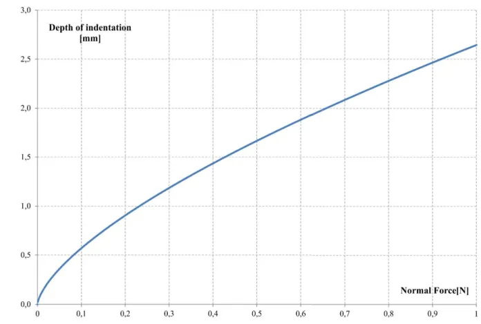
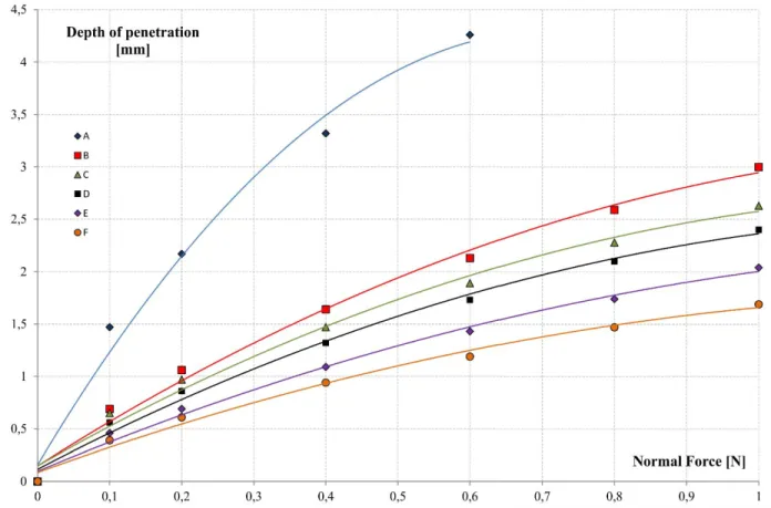
4.3.2 Depth of indentation / force relation ... 83
4.3.3 Tangential force loading ... 86
4.3.4 Quasi-static friction coefficient ... 87
4.4 Conclusions ... 92
5 NUMERICAL (FEM) ANALYSIS ... 94
5.1 Description of the parametric model ... 94
5.2 Definition of used materials ... 98
5.3 Static simulation – prototype “I” ... 99
5.3.1 Deformation vs. active length l1 ... 101
5.3.2 Deformation vs. remaining dimensions ... 102
5.4 Modal simulation – prototype I ... 104
5.5 Static simulation – prototype “II”... 107
5.6 Modal simulation – prototype II ... 109
5.7 Conclusions ... 112
6 EXPERIMENTAL VERIFICATION ... 113
6.1 Measurement methods and test bench ... 113
6.1.1 Measurement of maximal deformations ... 115
6.1.2 Measurement of frequency shifts... 116
6.1.3 Measurements of impedance ... 117
6.1.4 Tested material samples... 118
6.2 Measurement results ... 119
6.2.1 Deformations characteristics ... 119
iv
6.2.3 Electromechanical impedance ... 122
6.2.4 Equivalent circuit parameters ... 127
6.3 Conclusions ... 131
7 FINAL CONCLUSIONS ... 132
7.1 Research results and achievements ... 132
7.2 Future research works ... 136
LIST OF FIGURES ... 137
LIST OF TABLES ... 141
BIBLIOGRAPHY ... 142
v
The most exciting phrase to hear in science, the one that heralds new discoveries, is not 'Eureka!' but 'That's funny...'
vi
P
RAGNĘ SERDECZNIE PODZIĘKOWAĆ
Promotorowi Prof. Jean-François Rouchon, za wsparcie podczas moich studiów oraz staży badawczych w Tuluzie. Za liczne porady i owocne dyskusje przez cały okres realizacji pracy doktorskiej. Przede wszystkim jednak, za stworzenie przyjaznej i koleżeńskiej atmosfery sprzyjającej pracy w laboratorium.
Promotorowi dr hab. inż. Mieczysławowi Ronkowskiemu, prof. nadzw PG, za zachętę oraz umożliwienie studiów doktoranckich w Gdańsku i w Tuluzie. Za liczne porady na każdy temat oraz za pomoc przy opracowaniu rozprawy.
Profesor Marii Pietrzak-Dawid, za nieocenioną pomoc i wiele rad podczas moich studiów oraz staży badawczych w Tuluzie.
Dr inż. Grzegorzowi Kostro, mojemu promotorowi pomocniczemu, za liczne rady oraz poświęcony czas w okresie moich studiów doktoranckich.
Dr. François Pigache, mojemu promotorowi pomocniczemu, za pomoc i cenne porady, zwłaszcza w końcowym etapie realizacji rozprawy.
Dominique Harribey, za nieocenioną pomoc w realizacji prototypów, oraz eksperymentów przeprowadzonych w laboratorium LAPLACE.
Chciałbym szczególnie podziękować moim rodzicom oraz siostrze Agnieszce, za nieustającą miłość, zrozumienie i wsparcie podczas moich studiów doktoranckich w Gdańsku i w Tuluzie.
Chciałbym również podziękować moim kolegom z Katedry Energoelektroniki i Maszyn Elektrycznych: Michałowi, Filipowi, Rolandowi, Dominikowi. Z przyjemnością poznałem i spędzałem czas z wspaniałymi ludźmi z Erasmusa i N7, w szczególności: Carlosem, Driesem, Eleną, Fernandą, Faycelem, Hemzą, Maxem, Remim, Marcinem i Maćkiem. To były piękne czasy.
Na koniec, chciałbym podziękować Ani, mojej ukochanej, za wyrozumiałość oraz cierpliwość, kiedy nie było mnie obok niej.
vii
A
CKNOWLEDGEMENTS
I would like to express gratitude to my supervisor, prof. Jean-François Rouchon, for his guidance and support during my study and internships in France. For a lot of numerous advices and fruitful essential and scientific discussions throughout the course of this project, but most of all for creating very friendly and pleasant atmosphere at the LAPLACE laboratory.
I would like to extend my deepest gratitude to my supervisor, Prof. Mieczysław Ronkowski for his encouragement and inspiration to take up the PhD studies in Gdańsk and in Toulouse. Prof. Ronkowski has been a great advisor in both, matters of science and day-to-day life, throughout the course of my PhD studies.
I would like to give special thanks to Prof. Maria Pietrzak-Dawid for her friendly and energetic attitude in every-day life. She has given an enormous help during my studies and research work at INP-ENSEEIHT-LAPLACE from the first day. It would be impossible without Her to complete the PhD studies in Toulouse.
I would like to thank my co-supervisor, PhD Grzegorz Kostro for all the help and technical and non-technical advices and discussions, he gave me during the course of my PhD studies.
I would like to thank my co-supervisor, PhD François Pigache for all the help and precious advices, especially during the final stages of my research work.
I would like to express my gratitude to Dominique Harribey for introducing me into the lab and realization of the piezoelectric sensor/actuator prototype.
I would like to thank my family for everlasting love, understanding and support through my studies in Poland and in France.
Also, I would like to thank my friends and fellow PhD students at Power Electronics and Electrical Machines group: Michał, Filip, Roland, Dominik. Moreover, I enjoyed spending time with my friends from Erasmus and N7, especially: Carlos, Dries, Elena, Fernanda, Faycel, Hemza, Max, Remi, Marcin and Maciek. It was truly a magical time.
Last but not least, Ania, my love, thank you for your support, understanding and patience when I needed to travel away from you.
viii
R
EMERCIEMENTS
Je voudrais remercier le Professeur Jean-François Rouchon, pour ses conseils et soutien pendant mon séjour en France. Pour de nombreux conseils et discussions techniques précieux tout au long de ce projet, mais surtout pour créer une atmosphère très amicale et agréable au laboratoire.
Je tiens à remercier vivement le Professeur Mieczysław Ronkowski pour encouragement et d'inspiration pour débuter les études de doctorat à Gdańsk et plus tard à Toulouse. Prof. Ronkowski a été un grand conseiller à la fois, les questions de la science et de la vie.
Je voudrais remercier tout particulièrement la Professeur Maria Pietrzak-Dawid pour son attitude amicale et énergique. Elle a été une grande aide pendant de mes études et de travaux de recherche à Toulouse, depuis le début. Il serait impossible sans Elle.
Je voudrais remercier mon co-directeur, le Docteur Grzegorz Kostro pour toute l'aide et des conseils et des discussions techniques au cours de mes études de doctorat.
Je voudrais remercier mon co-directeur, le Docteur François Pigache pour toute l'aide et des conseils précieux, particulièrement pendant les dernières étapes de mon travail.
Je voudrais exprimer ma gratitude à ingénieur Dominique Harribey pour me présenter le laboratoire et aider de nombreux aspects techniques et mécaniques des expériences.
Je tiens à remercier ma famille pour la compréhension et leur soutien par mes études en Pologne et en France.
Je remercie également mes collègues du département: Michał, Filip, Roland, Dominik et tous mes collègues d'Erasmus et N7 en particulier: Carlos, Dries, Elena, Fernanda, Faycel, Hemza, Max, Remi, Marcin et Maciek. Ce était le temps vraiment magiques.
Ania, mon amour, je te remercie pour ton soutien, de compréhension et de patience quand je ne suis pas avec toi.
ix
S
TRESZCZENIE
Podstawowym celem rozprawy doktorskiej było opracowanie koncepcji, modelu analitycznego, modelu wirtualnego, modelu numerycznego, realizacja i weryfikacja eksperymentalna piezoelektrycznego rezonansowego sensora/aktuatora do pomiaru procesu starzenia się ludzkiej skóry. Rozprawę zrealizowano jako wspólny doktorat Politechniki Gdańskiej z uczelnią INP- ENSEEIHT-LAPLACE w Tuluzie, Francja. Praca doktorska jest kontynuacją dotychczasowych badań nad przetwornikami piezoelektrycznymi prowadzonymi w Katedrze Energoelektroniki i Maszyn Elektrycznych Politechniki Gdańskiej. Pracę częściowo zrealizowano w ramach staży naukowych w laboratorium LAPLACE w Tuluzie.
Opracowano koncepcję przetwornika do pomiaru właściwości mechanicznych charakteryzujących tkanki miękkie, w tym skórę. Rezonansowy, przetwornik piezoelektryczny zginający, zwany dalej przetwornikiem typu „unimorph”, został wybrany na podstawie wymagań, które sformułowano w aspekcie właściwości ludzkiej skóry. W świetle metod opisu właściwości ludzkiej skóry zaproponowano nowatorskie podejście, wykorzystując dynamiczną metodę wgłębienia. Innowacyjność koncepcji polega na wsparciu dynamicznej metody wgłębienia przez zastosowanie rezonansowego sensora/aktuatora piezoelektrycznego jako wgłębnika (ang. indentation device). Takie rozwiązanie pozwala wykorzystać szereg atrakcyjnych właściwości piezoelektrycznych przetworników elektromechanicznych.
Rozprawa jest podzielona na siedem rozdziałów. Rozdział 1 opisuje tezę i cele pracy doktorskiej. Rozdział 2 przedstawia opis zjawiska piezoelektrycznego i jego zastosowania w dziedzinie medycyny i bioinżynierii. W rozdział 3 sformułowano wymagania stawiane rozważanemu przetwornikowi. Uzasadniono wybór przetwornika typu unimorph. W rozdziale 4 przedstawiono model analityczny przetwornika unimorph, uwzględniający statyczne obliczenia odkształceń, schemat zastępczy przetwornika oraz opis warunków pracy kontaktu pomiędzy przetwornikiem a badanymi materiałami. Rozdział 5 zawiera analizę numeryczną przetwornika unimorph z wykorzystaniem opracowanego modelu wirtualnego i metod polowych (FEM). Rozdział 6 opisuje realizację weryfikacji eksperymentalnej opracowanych modeli przetwornika unimorph, a w szczególności pomiarów zbudowanych prototypów przetwornika unimorph. Ostatni rozdział zawiera ogólne wnioski i osiągnięcia rozprawy, sformułowane na podstawie przeprowadzonych rozważań i wyników badań, a także wskazania celów przyszłych prac badawczych.
x
A
BSTRACT
The main goal of the dissertation was following: preparation of a new concept, implementation and analysis of the piezoelectric resonant sensor/actuator for measuring the aging process of human skin. The research work has been carried out in the framework of cooperation between the INP-ENSEEIHT-LAPLACE, Toulouse, France, and at the Gdansk University of Technology, Faculty of Electrical and Control Engineering, Research Group of Power Electronics and Electrical Machines, Gdańsk, Poland.
A concept of transducer for the characterization of mechanical properties of soft tissues was presented. The piezoelectric resonant, bending transducer, referred to as “unimorph transducer” was chosen from different topologies of piezoelectric benders based on the fulfillment of the stated requirements. The innovation of the project lies in the integration of the dynamic indentation method by using a unimorph as an indentation device. This allows the use of a number of attractive electromechanical properties of piezoelectric transducers.
The thesis is divided into seven chapters. Chapter 1 states the thesis and goals of the dissertation. Chapter 2 presents piezoelectric phenomenon and piezoelectric applications in the fields of medicine and bioengineering. Chapter 3 describes the requirements for the developed transducer. The choice of unimorph transducer is justified. Chapter 4 presents an analytical description of the unimorph transducer, including the calculations of static deformations, equivalent circuit description, and description of the contact conditions between the transducer and the tested materials. Chapter 5 contains the numerical analysis of the unimorph transducer using FEM virtual model. Results of static and modal simulations are described for two considered geometries of the transducer. Chapter 6 describes the experimental verification process of analytic and numerical models developed for unimorph transducer. The final chapter includes general conclusions concerning obtained research results and achievements, as well as possible future works.
xi
R
ESUME
L’objectif de cet projet est la conception, réalisation et caractérisation d’un actionneur / capteur piézoélectrique piézorésonant destiné à la mesure du vieillissement de la peau humaine. L’étude présentée est le fruit d’une collaboration entre le groupe de recherche de l'Electrodynamique du INP-ENSEEIHT (Toulouse), LAPLACE Laboratoire de Recherche et l'École Polytechnique de Gdańsk, Département Génie Electrique et Automatique.
Un concept d’actionneur / capteur pour la caractérisation des propriétés mécaniques des tissus mous a été présenté. Un actionneur piézoélectrique résonant, appelé "unimorphe" a été choisi parmi les différentes structures piézoélectriques fondées sur le cahier des charges. L'innovation du projet réside dans l'intégration de la méthode d'indentation dynamique en utilisant un unimorphe comme dispositif d'indentation. Ceci permet l'utilisation d'un certain nombre de propriétés électromécaniques favorables des transducteurs piézo-électriques.
Ce mémoire est divisé en 7 chapitres. Le chapitre 1 présente la thèse et ses objectifs. Le chapitre 2 présente le phénomène piézoélectrique et les applications piézoélectriques dans les domaines de la médecine et de la bioingénierie. Le chapitre 3 décrit le cahier des charges pour le transducteur développé. Le choix du transducteur unimorphe est ainsi justifié. Le chapitre 4 présente une description analytique du transducteur unimorphe, y compris les calculs de déformations statiques, la description du circuit équivalent de Mason, et la description des conditions de contact entre la sonde d'indentation et les matériaux testés. Le chapitre 5 contient l'analyse numérique du transducteur unimorphe en utilisant le modèle virtuel MEF. Les résultats de simulations statiques et modales sont décrits par deux géométries considérées du transducteur. Le chapitre 6 décrit le processus de vérification expérimentale des modèles analytiques et numériques développés pour le transducteur unimorphe. Enfin, le dernier chapitre comprend des conclusions générales concernant les résultats de recherche obtenus, ainsi que les travaux futurs possibles.
xii
N
OTATIONS
Sij Strain tensor
Tkl Stress tensor
Ek Electric field tensor
Di Electric displacement tensor
sijkl, cijkl Compliance and stiffness tensors
εij, βij Permeability and impermeability tensors
k Electromechanical coupling coefficient
E, E* Young modulus, reduced Young modulus
d, e, g, h Piezoelectric constants u, w Displacement components
𝝋 Electric potential
𝝋̃, 𝝍 Stress and induction functions
δ, δ0, δAnsys Displacement at the free end of the transducer
p(r), q(r) Normal and shear pressure distribution
1/N Transformation ratio for the equivalent circuit
fR, fA Resonance and anti-resonance frequencies
A Displacement calculated from laser vibrometry
FN Normal force applied on the surface of the sample
RM, CM, LM Parameters of the equivalent circuit modelling the material properties
1
1 G
ENERAL
I
NTRODUCTION
Among the basic transduction mechanisms that can be used for electricity-to-vibration conversion, and vice-versa, piezoelectric transduction has received the most attention in the existing literature [41], [42], [45]. Piezoelectric phenomenon and piezoelectric materials are preferred in transduction process due to their large power densities and ease of application. One of the best example of such an application is a resonant piezoelectric sensor.
A resonant piezoelectric sensor is a device with an element vibrating at resonance state, which changes its output frequency, i.e., mechanical resonance frequency as a function of a physical parameter; it is proved to have major advantages over other physical resolution principles. Resonant piezoelectric sensors with various excitation and detection techniques have been reported in the available literature [66], and each one has its own advantages and disadvantages. Smart materials, in particular piezoelectric materials for excitation and detection, have numerous advantages like, relatively large power density, relatively large force, low actuation voltage, high energy efficiency, linear behavior, high acoustic quality, high speed and high frequency. In the design of resonant piezoelectric sensors an applications of sensor/actuator in collocation (arrangement) is usually used and provides a stable performance [28].
Nowadays, an increased scientific interest in dynamic measurement methods of soft tissues utilizing piezoelectric sensors can be observed. Such solutions are of the interest in biomedical and pharmaceutical industry (e.g. L'Oréal) applications. The piezoelectric sensors and actuators, due to their favorable characteristics, are likely to replace many of the current solutions for the measurement (assessment) of mechanical quantities characterizing soft tissues, i.e., detection of disease states, determining the aging process of human skin, etc. [71].
1.1 Motivation
The research work described in this thesis has been conducted as part of the European Union sponsored programme ERASMUS [12], and a project The Center for Advanced Studies
- the development of interdisciplinary doctoral studies at the Gdansk University of Technology in the key areas of the Europe 2020 Strategy, referred to as Advanced PhD [2].
2 The research work has been carried out in the framework of cooperation between the INP - ENSEEIHT - LAPLACE [34] (Laboratory on Plasma and Conversion of Energy), in Toulouse, France, and the Gdańsk University of Technology, Faculty of Electrical and Control Engineering, Power Electronics and Electrical Machines Research Unit in Gdańsk, Poland [51].
The LAPLACE Laboratory [34] is an inter-university research unit. Its advanced research programs covers the production, the transportation, the management, the conversion and the use of the electricity while concerning all the aspects right from the study of fundamental processes in solid and gas to the development of processes and systems. The major field of study concern the plasma discharges as well as plasma applications, the study of the dielectric materials (polymers, in particular) and their integration into the systems, the study and the design of the electrical systems, the optimization of the controls and the converters. One of the LAPLACE’s Laboratory research groups - GREM3 - is a leading research unit in the world in the field of piezoelectric technology and shape-memory alloys technology.
The research process described in this dissertation was divided into two main stages. The first stage was one-year studying and research programme in the frame of ERASMUS, which started in September 2011 at the INP-ENSEEIHT-LAPLACE. This programme, within the specialization of the “Transformation de l'Energie et Mécatronique avancée”, covered issues of power electronics, automation and mechatronics systems, and has been completed with the International Master research project and diploma. The first part of the carried out research covered the “Rotating-mode motor – simulations, manufacturing and measurements”, and also the “Hybrid piezoelectric motor” topics. The second part was a six-month International Master research project, concerning the piezoelectric sensor/actuator structure, entitled: “Sensor/actuator for measuring the aging process of human skin”.
The second stage of the research process was a 10-month research programme in the frame of the Advanced PhD, started in October 2013. It has been divided into 7-month research work carried out at the Power Electronics and Electrical Machines Research Unit, and 3-month internship at the LAPLACE Laboratory. The subject of the research work conducted at the LAPLACE Laboratory was “Analysis and measurement of resonant piezoelectric
3 sensor/actuator structure”, and has covered the performance analysis of a new prototype of unimorph resonant piezoelectric transducer.
It should be emphasized that the research works in the field of piezoelectric technology have not been carried out on a wide scale in Poland, until now. The study carried out in the frame of this thesis can be considered as a pioneer research works in Poland. It focuses on application of piezoelectric transducers for measurement the mechanical properties of soft materials.
1.2 Objectives of the dissertation
A dynamic indentation method for measurement of the mechanical properties characterizing the soft tissues is used in this dissertation. It is based on measurement the normal component of force applied on the surface of the material as a function of the displacement imposed by the indenter. In addition to a static force, vibrations are injected on the surface of the tested sample. Within this method a piezoelectric system is introduced to make use of the electromechanical impedance characterization of resonant piezoelectric actuators [28], [58]. The key aspect of the research work lies in aiding of the dynamic indentation method by using a resonant transducer as an indentation device. This approach allows to use a number of favorable electromechanical properties of piezoelectric transducers: high sensitivity, generation of vibrations in a wide frequency range, control of the measurement conditions by changing the work mode of the transducer, use of the electromechanical impedance methods, simple design and compact dimensions.
Proposition of the thesis is as follows:
The fundamental mechanical properties of a visco-elastic medium resembling a human skin, such as rigidity, flexibility and viscosity, can be determined by measuring the electromechanical impedance variation of the piezoelectric transducer contacting the tested medium.
In order to verify the proposition of the thesis a full research cycle was carried out, that covered: analytical study, numerical analysis (FEM simulations), prototype realization, and experimental verification of the considered (developed) piezoelectric sensor/actuator structures.
4 The scope of the dissertation included:
State of the art study of the considered issues in the available literature.
Development of the concept of piezoelectric sensor/actuator structures.
Analytical study of the developed/considered piezoelectric sensor/actuator.
Application of equivalent circuit representation method (modified Mason's equivalent circuit).
Application of the electromechanical impedance concept to determine the
parameters of the equivalent circuit models of the considered piezoelectric sensor/actuator.
Development of a virtual model (CAD techniques) of the considered sensor/actuator
in operating mode.
Numerical (FEM ANSYS software) analysis of the virtual model of the considered
piezoelectric sensor/actuator.
Experimental verification of the developed piezoelectric sensor/actuator prototypes.
1.3 Thesis layout
To describe each of the stages of the research work in a systematic way, the thesis is organized into seven chapters.
In chapter 1 the motivation and objectives of the research work are briefly described. In chapter 2 the piezoelectric phenomenon, history of piezoelectricity, piezoelectric materials and their structures are presented. Examples of piezoelectric applications in the fields of medicine and bioengineering are considered.
In chapter 3 the requirements are formulated for the developed transducer. They are based on the properties of soft tissues, human skin in particular. The structures of piezoelectric bending transducer are presented. Choice of unimorph transducer is justified. Two prototypes of unimorph transducer are described in detail.
In chapter 4 an analytical description of the unimorph transducer is carried out. It includes the calculations of static deformations, equivalent circuit description of the transducer working
5 near resonance of the system. And finally, the contact conditions between the transducer and the tested materials are described using the Hertz theory.
In chapter 5 the numerical (FEM simulation) analysis of the unimorph transducer virtual model is carried out using Ansys software. Results of static and modal simulations are described for two considered geometries of the transducer.
In chapter 6 experimental verification of the developed piezoelectric sensor/actuator prototypes is presented. Also the results of the experimental analysis are discussed.
In the last chapter 7 the final conclusions concerning obtained research results and achievements, as well as possible future works are presented.
6
2 P
IEZOELECTRICITY
:
MATERIALS AND APPLICATIONS
2.1 Physical phenomenon
The piezoelectric effect occurs in materials where an externally applied elastic strain causes a change in electric polarization which generates a charge and a voltage across the material. The converse piezoelectric effect is produced by an externally applied electric field, which changes the electric polarization, which in turn produces an elastic strain.
For a crystal to exhibit the piezoelectric effect, its structure should have no center of symmetry. A stress (tensile or compressive) applied to such a crystal will alter the separation between the positive and negative charge sites in each elementary cell leading to a net polarization at the crystal surface (direct piezoelectric effect). The effect is reciprocal, so that if the crystal is exposed to an electric field, it will experience an elastic strain causing its length to increase or decrease according to field polarity (the converse piezoelectric effect). Both effects are schematically demonstrated in the Figure 2.1:
Figure 2.1 Illustrations of piezoelectric effects: direct piezoelectric effect a), b), c) and reverse piezoelectric effect d), e), f); the scale is extended for clarity
7
2.1.1 History
In the middle of eighteenth century Carolus Linnaeus and Franz Aepinus first observed that certain materials, such as crystals and some ceramics, generate electric charges due to a temperature change. Piezoelectricity as a research field in crystal physics was initiated by the brothers Jacques Curie (1856–1941) and Pierre Curie (1859–1906) with their studies [21], [22]. They discovered an unusual characteristic of certain crystalline minerals as tourmaline, quartz, topaz, cane sugar and Rochelle salt. It was found that tension and compression generated voltages of opposite polarity and proportional to the applied load. This was called by Hankel the piezoelectric effect [67].
The word piezoelectricity comes from Greek and means electricity resulting from pressure (Piezo means pressure in Greek). In the year following the discovery of the direct effect, Gabriel Lippman [16] predicted the existence of the converse effect basing on fundamental thermodynamic principles. Before the end of 1881 the brothers Curies confirmed experimentally the existence of the converse effect. They showed that if one of the voltage-generating crystals was exposed to an electric field it lengthened or shortened according to the polarity of the field, and in proportion to its strength.
Until the beginning of the century, the piezoelectricity did not leave the laboratories. In 1917, Paul Langevin, a French physicist, developed a submarine detector based on the piezoelectric effect, resulting in an improved method for submarine ultrasonic echo detection, namely sonar. This invention was the beginning of practical application of the piezoelectric effect. The success of Langevin’s invention opened up opportunities for piezoelectric materials in underwater applications as well as a host of other applications such as ultrasonic transducers, microphones, accelerometers, etc. [46].
In 1945 piezoelectricity was introduced into the global market, thanks to discovery of the
mixed oxide compound barium titanate BaTiO3. It was a ferroelectric which could be easily
fabricated and shaped at low price and could be made piezoelectric with constants many times higher than natural materials by an electrical poling process. This material was of stable perovskite type, which is one of the fundamental crystal lattice structures (described in chapter 2.1.3). The discovery of lead zirconate titanate (PZT) families of materials in the 1950s was
8 the beginning of the modern history of piezoelectricity. Until to today, PZT material is one of the most widely used piezoelectric materials [5].
A variety of new areas, such as ultrasonic delay lines, ultrasonic medical therapy and diagnostics, level gauges, devices for continuous industrial control of physical and chemical substance properties, and other devices with wide range of applications were found for piezoelectric transducers. At the same time, more effective electro-acoustic transducers became available. Piezoelectric transducers have been used for measuring wide variety of mechanical and thermal parameters including: effort, pressure, acceleration, weight, angular speed, torques, deformations, temperature etc. Considering accuracy, these devices in many cases surpassed transducers based on other detection principles [66].
Nowadays, piezoelectric transducers are used in various fields of industry, including but not limited to medicine and bioengineering for ultrasonic tomography, pulse measurements, tone measurements, urology, ophthalmology, etc. [31], [36]. The section 2.4 covers the industry applications of piezoelectric materials and transducers in more details.
2.1.2 Materials
Materials that exhibit a significant and useful piezoelectric effect fall into three main groups: natural and synthetic crystals, polarized piezoelectric ceramics, and certain polymer films. The natural Piezoelectric materials are crystals like quartz (SiO4), Rochelle salt,
Tourmaline-group minerals, Topaz, cane sugar, and some organic substances as silk, wood, enamel, dentin, bone, hair, rubber. In the atomic structure of those materials the change in the position of the atoms due to applied stress leads to the formation of net dipole moments that causes polarization and an electric field, respectively.
Since 1935 attempts were made to produce piezoelectric crystals, which could replace
quartz. Piezoelectric crystals such as ammonium and potassium salts (NH4H2PO4 – ADP,
KH2PO4 – KDP), ethylene diamine tartrate (EDT), dipotassium tartrate (DKT) and lithium
sulphate monohydrate (LH) were developed. Many of these materials are no longer in use due to development and production of artificial quartz, ferroelectric crystals or piezoelectric ceramics. With the exception to quartz few single crystals are used in piezoelectric devices.
9 material properties depending on the cut of the materials and the direction of bulk or surface wave propagation [24].
The discovery of the strong piezoelectric properties of ferroelectric ceramics was a major milestone in applications of piezoelectricity. The ferroelectric ceramics are the most common piezoelectric material in today’s engineering applications. Among them, polycrystalline
ceramics like barium titanate (BaTiO3) and lead zirconate titanate (PZT) are the most popular
materials, in particular due to the low manufacturing costs and the almost arbitrary shaping possibilities compared to single crystalline piezoelectrics. Furthermore, they exhibit outstanding piezoelectric and dielectric properties, which make them particularly indispensable for the field of actuators [11].
Lead zirconate titanate (PZT) are based on the Perovskite structure of ferroelectric
crystals. The general chemical formulae of perovskite crystal structure is ABO3 , where A are
larger metal ions, usually lead or barium, B is a smaller metal ion, usually titanium or zirconium. The perovskite structure is the simplest arrangement where the corner-sharing oxygen octahedra are linked together in a regular cubic array with smaller cations occupying the central octahedral B-site, and larger cations filling the interstices between octahedra in the
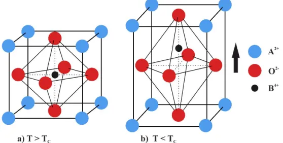
larger A-site. Figure 2.2 shows the crystal structure of a piezoelectric ceramic (BaTiO3) at
temperature above and below Curie point.
Figure 2.2 Crystal structure of a traditional piezoelectric ceramic (BaTiO3) at temperature a) above, and
10 Piezoceramics do not have a macroscopic piezoelectric behavior, although the individual single-crystal grain has piezoelectric characteristics. The spontaneous polarization can be reoriented by an external electric filed: ferroelectric ceramics must be artificially polarized by a strong electric field while the material is heated above its Curie point and then slowly cooled with field applied. Remnant polarization being retained, the material exhibits macroscopic piezoelectric effect [49].
“Poling” is the process of generating net remnant polarization in the material by applying sufficiently high electric field. When an electric field is applied to a ferroelectric material, the microscopic ferroelectric domains orient themselves in the direction of the applied field. As the electric field is increased, more and more domains get oriented and, at a sufficiently high electric field, almost all the domains are in the same direction resulting in a single large domain. The material in this state possesses maximum polarization. If the material is maintained at a high temperature (close to the transition temperature) while the electric field is applied, the orientation of the domains is facilitated. The process of poling involves the following steps: 1. The material is heated to a temperature slightly less than the transition temperature and held
at the temperature.
2. A sufficiently high electric field is applied to the material for about 2 – 3 h. All the ferroelectric domains get oriented in the direction of the electric field, and the material attains saturation polarization.
3. The material is cooled to room temperature with the electric field kept on. The domains remain frozen in the oriented state.
4. The electric field is now put off. The material remains in the maximum polarization state with most of the domains oriented in the same direction.
11 Figure 2.3 Polling of a piezoelectric material: a) the domains are randomly oriented when the material is unpoled; b) The domains are oriented in the direction of the applied electric field, c) relaxation of remnant
polarization due to aging
Piezoelectric ceramics are usually divided into two groups. The antonyms “hard” and “soft” doped piezoelectric materials refer to the ferroelectric properties, i.e. the mobility of the dipoles or domains and hence also to the polarization/depolarization behavior. “Hard” piezoelectric materials are those materials whose properties are stable with temperature, electric field, and stress. They are used in applications requiring high power actuation or projection. The applications often have a narrow bandwidth, but are usually operated either at resonance or well under resonance. “Soft” piezoelectric materials are those materials whose properties have been enhanced for sensing, actuation, or both. They have high coupling and high permittivity. Property enhancement was made at the expense of temperature, electric field, and stress stability [13].
The most recent group of piezoelectric materials, PVDF films (polyvinylidene fluoride), was discovered in 1969 in Japan. PVDF can be of two types: piezo-polymer in which the piezoelectric material is immersed in an electrically passive matrix (for instance PZT in epoxy matrix) and piezo-composites that are composite materials made from two different ceramics
(for example BaTiO3 fibers reinforcing a PZT matrix).With piezo- and pyroelectric coefficients
being less than that of crystalline or ceramic piezoelectrics, polymers have found niche commercial applications in different fields, ranging from sensor systems, accelerometers and non-destructive testing (contactless switches) to fundamental research applications, such as photo-pyroelectric spectroscopy. This class of materials is also used for manufacturing piezo
films of low thickness (less than 30 µm), which may be laminated on the structural materials
12
2.1.3 Physical structure
There are 32 crystal classes which are divided into the following seven groups: triclinic, monoclinic, orthorhombic, tetragonal, trigonal, hexagonal and cubic. These groups are also associated with the elastic nature of the material where triclinic represents an anisotropic material, orthorhombic represents an orthotropic material and cubic are in most cases isotropic materials. Only 20 of the 32 classes allow for piezoelectric properties. Ten of these classes are polar, i.e. show a spontaneous polarization without mechanical stress due to a non-vanishing electric dipole moment associated with their unit cell. The remaining 10 classes are not polar, i.e. polarization appears only after applying a mechanical load.
Figure 2.4 shows a simple molecular model of piezoelectric material. It explains the generating of an electric charge as the result of a force exerted on the material. Before subjecting the material to some external stress, the gravity centers of the negative and positive charges of each molecule coincide. Therefore, the external effects of the negative and positive charges are reciprocally cancelled. As a result, an electrically neutral molecule appears (Figure 2.4a). When exerting some pressure on the material, its internal reticular structure can be deformed, causing the separation of the positive and negative gravity centers of the molecules and generating little dipoles (Figure 2.4b). The facing poles inside the material are mutually cancelled and a distribution of a linked charge appears in the material’s surfaces - the material is polarized (Figure 2.4c). This polarization generates an electric field and can be used to transform the mechanical energy used in the material’s deformation into electrical energy [7].
13 Figure 2.4 Simple molecular model of piezoelectric material: a) an electrically neutral molecule appears,
b) generating little dipoles, c) the material is polarized
2.1.4 Manufacturing process
Several techniques have been adopted for fabrication of PZT. The most commonly used techniques are: Solid-state reaction technique, coprecipitation technique and sol–gel technique. PZT in the form of fine powders can be obtained from the above techniques. Other methods such as tape-casting and chemical vapor deposition techniques are used for obtaining PZT in the form of thick or thin films.
In Solid – State Solution technique, the oxides (PbO, TiO2 and ZrO2 ) in suitable
proportions are mixed well and subjected to solid-state reaction by the calcination process. The calcination process involves heating the oxides to about 650 °C and maintaining at that temperature for 2 to 3 hours. The product is then heated to about 850 °C. The mixture is milled to obtain a particle size of about 1 μm. Ball milling is done using zirconia balls to avoid contamination during milling. The process has been standardized and optimized to get submicron – sized powder with a very narrow particle size distribution [41].
14 For transducer and actuator applications, PZT is required in the form of discs, cylinders, or plates of different dimensions. The PZT powders fabricated by the techniques mentioned earlier are used to form products of desired shapes and sizes. The powder is initially mixed with a polymer binder and pressed in molds using high pressure. The techniques used for pressing are: uniaxial pressing and isostatic pressing.
In uniaxial pressing, the powder is compacted in a rigid die by applying pressure along a single axis using pistons. In isostatic pressing, the pressure is applied uniformly from all sides. This method gives better uniformity of green density than uniaxial pressing. Isostatic pressing is achieved by keeping the powder in a rubber bag and immersing the bag in a liquid which acts as a pressure transmitter. Hydrostatic pressure is applied on the rubber bag to compact the powder.
The example of manufacturing process based on Ferroperm Piezoceramics involves a number of stages shown schematically in Figure 2.5. The first step is weighing, dry mixing and ball milling of the raw materials. The uniform mixture is then heat treated (calcined), during which the components react to form the polycrystalline phase. The calcined powder is ball milled to increase it' s reactivity, and granulated , with the addition of a binder, to improve its pressing properties. After shaping by dry – pressing, the binder is burnt out by slowly heating the green ceramics to around 700 °C. The parts are transferred to another furnace, where they are sintered between 1200 and 1300 °C. The dimensional tolerance of fired parts (± 3 %) is improved by cutting, grinding, lapping etc.. Electrodes are applied either by screen printing or by vacuum deposition . In the next step, poling is carried out by heating in an oil bath at 130 – 220 °C, and applying an electrical field of 2 – 8 kV/mm to align the domains in the material. The oil bath is used as a heat source and to prevent flash over. Final inspection includes testing of electrode-ceramic bonding as well as measurement of dimensional tolerances, dielectric and piezoelectric properties.
15 Figure 2.5 The manufacturing process of piezoelectric ceramics [14]
2.2 Constitutive equations
In this section, the constitutive equations for linear piezoelectricity are presented in tensor as well as matrix form. Only the piezoelectric coupling is considered (the thermoelectricity is neglected) and the quasi – electrostatic approach is used (the phase velocities of acoustic waves are several order of magnitude less than the velocities of electromagnetic waves).
2.2.1 Global relations
When writing the constitutive equation for a piezoelectric material, changes of strain and electrical displacement in three orthogonal directions caused by cross – coupling effects due to applied electrical and mechanical stresses must be taken into account. Tensor notation is first adopted, and the reference axes are shown in Figure 2.6. The state of strain is described by a second rank tensor Sij and the state of stress is also described by a second rank tensor Tkl.
The quantities linking the stress tensor to the strain tensor, compliance sijkl, and stiffness cijkl,
are then fourth rank tensors. The correlation between the electric field Ek (first rank tensor) and
the electric displacement Di (also a first rank tensor) is the permittivity εik, which is a second
rank tensor. The piezoelectric equations can be written as:
Raw materials Mixing Calcining (900ºC) Milling
Granulation Pressing Binder Burnout
(600 - 700ºC)
Sintering (1200 - 1300ºC)
16
𝑆𝑖𝑗 = 𝑠𝑖𝑗𝑘𝑙𝐸 𝑇𝑘𝑙 + 𝑑𝑖𝑗𝑘𝐸𝑘 (2.1)
𝐷𝑖 = 𝑑𝑖𝑗𝑘𝑇𝑗𝑘+ 𝜀𝑖𝑗𝑇𝐸
𝑗 (2.2)
where dijk is the piezoelectric constant (third rank tensor). Superscripts T and E denote
that the dielectric constant εij and the elastic constant sijkl are measured under conditions of
constant stress and constant electric field respectively [70].
In general, a first rank tensor has three components, a second rank tensor has nine components, a third rank tensor has 27 components and a fourth rank tensor has 81 components. Not all the tensor components are independent. Both these relations are orientation-dependent; they describe a set of equations that relate these properties in different orientations of the material. The crystal symmetry and the choice of reference axes reduce the number of independent components. A convenient way of describing them is by using axis directions as shown in Figure 2.6.
Figure 2.6 Reference axes description
2.2.2 Matrix notation
The convention is to define the poling direction as the 3 – axis, the shear planes are indicated by the subscripts 4, 5 and 6 and are perpendicular to directions 1, 2 and 3 respectively. This simplifies the notations introduced above, where a 3-subscript tensor notation (i,j,k =1,2,3) is replaced by a subscript matrix notation (i=1,2,3 and j=1,2,3,4,5,6), and a 2-subscript tensor notation (i,j =1,2,3) is replaced by a 1-2-subscript matrix notation (i=1,2,3,4,5,6). See
17 Table 2.1. 𝑐𝑖𝑗𝑘 = 𝑐𝑝𝑞 (2.3) 𝑒𝑖𝑘𝑙 = 𝑒𝑖𝑞 (2.4) 𝑇𝑖𝑗 = 𝑇𝑝 (2.5) 𝑆𝑖𝑗 = 𝑆𝑝 when 𝑖 = 𝑗 (2.6) 2𝑆𝑖𝑗 = 𝑆𝑝 when 𝑖 ≠ 𝑗 (2.7)
Table 2.1 Matrix notation ij or kl p or q 11 1 22 2 33 3 23 or 32 4 13 or 31 5 12 or 21 6
With this notations constitutive equations can be written in matrix form:
{𝑆} = [𝑠]{𝑇} + [𝑑]{𝐸} (2.8)
{𝐷} = [𝑑]𝑇{𝑇} + [𝜀]{𝐸} (2.9)
where the superscript T stands for the transposed; the other superscripts have been omitted. Assuming that the coordinate system coincides with the orthotropy axes of the material and that the direction of polarization coincides with direction 3, the explicit forms of (2.8) and (2.9) are:
18 { 𝑆11 𝑆22 𝑆33 2𝑆23 2𝑆31 2𝑆12} = [ 𝑠11 𝑠12 𝑠13 0 0 0 𝑠12 𝑠22 𝑠23 0 0 0 𝑠13 𝑠23 𝑠33 0 0 0 0 0 0 𝑠44 0 0 0 0 0 0 𝑠55 0 0 0 0 0 0 𝑠66]{ 𝑇11 𝑇22 𝑇33 𝑇23 𝑇31 𝑇12} + [ 0 0 𝑑31 0 0 𝑑32 0 0 𝑑33 0 𝑑24 0 𝑑15 0 0 0 0 0 ] { 𝐸1 𝐸2 𝐸3} (2.10) { 𝐷1 𝐷2 𝐷3} = [ 0 0 0 0 𝑑15 0 0 0 0 𝑑24 0 0 𝑑31 𝑑32 𝑑33 0 0 0 ] { 𝑇11 𝑇22 𝑇33 𝑇23 𝑇31 𝑇12} + [ 𝜀11 0 0 0 𝜀22 0 0 0 𝜀33] { 𝐸1 𝐸2 𝐸3} (2.11)
2.2.3 Coupling modes
As can be seen in equations (2.10) and (2.11), the only non-zero elements of piezoelectric constants matrix of ceramic materials are: d33, d31 (equal to d32) and d15 (equal to d24). Therefore, the electro-elastic coupling operates in three basic modes called longitudinal mode (“33”), transversal mode (“31”) and shear mode ("15"). The constitutive equations associated with each of these modes and associated effects, in the case of a rectangular bar, are explained in the Table 2.2.
Thus, a bar polarized along its length and subjected to a difference of potential applied
between two electrodes perpendicular to its polarization axis Ox3 undergoes, by converse
piezoelectric effect, a change in length in the same direction. Of course, this assumes that the
bar is free to deform, which is particularly the case for unloaded operation (T3 = 0). In a second
configuration, the bar can be polarized in its thickness direction and subjected to an external field oriented in the same direction. Due to transverse coupling a change in length perpendicular to the polarization direction can be observed. Finally, the application of an
electric field perpendicular to the direction of polarization, for example along the axis Ox3,
tends to turn the elementary dipoles around the axis Ox2. The resulting deformation can be
defined as the shear mode. Similar reasoning can be developed for the direct piezoelectric effect. From these three forms of elementary interaction, a wide variety of configurations can be produced by playing with the sample’s geometry (plate, disc, ring, tube, etc.) as well as its polarization type (axial, thickness, etc.). Various types of piezoelectric transducers based on piezoelectric materials are available, thanks to the adaptation of these elementary coupling modes, used independently or in combination.
19 Table 2.2 Basic electromechanical coupling modes of piezoelectric material
Constitutive equations Illustration of the mode
Longitudinal mode {𝑆3 = 𝑠33𝐸 ∙ 𝑇3+ 𝑑33∙ 𝐸3
𝐷3 = 𝑑33∙ 𝑇3+ 𝜖33𝑇 ∙ 𝐸3
Longitudinal mode of operation: extension along ox3 axis; d33>0; S3 and E3 of the same sign;
electrode surface represented by grey color
Transversal mode {𝑆3 = 𝑠11𝐸 ∙ 𝑇1+ 𝑑31∙ 𝐸3
𝐷3 = 𝑑33∙ 𝑇3+ 𝜖33𝑇 ∙ 𝐸 3
Transversal mode of operation: extension along ox1; d31<0; S1 and E3 of opposite sign
Shear mode { 𝑆5 = 𝑠44𝐸 ∙ 𝑇5+ 𝑑15∙ 𝐸1
𝐷1 = 𝑑15∙ 𝑇5+ 𝜖11𝑇 ∙ 𝐸 1
Shear around ox2 axis; d15>0; S5 and E1 of
20
2.2.4 Coupling coefficients
Another fundamental parameter used in electromechanical applications is the electromechanical coupling factor k. It is a dimensionless number related to conversion of energy from a mechanical source to electrical work, or vice versa, over an idealized work cycle. It is expressed as:
𝑘2 =Converted Mechanical Energy
Input Electrical Energy (2.12)
or:
𝑘2 = Converted Electrical Energy
Input Mechanical Energy (2.13)
The (static) coupling factors can be related to series and parallel - resonance frequencies, fs and
fp respectively, (dynamic behavior) of various specific modes and shapes (Table 2.3).
Table 2.3 Electromechanical coupling factors for different material shapes and polarization directions
Material Coupling Factor Shape
𝑘312 = 𝐴 1 + 𝐴 or 𝑘312 1 − 𝑘312 = 𝐴 𝐴 = 𝜋 2 𝑓𝑝 𝑓𝑠 tan [ (𝜋2) (𝑓𝑝− 𝑓𝑠) 𝑓𝑠 ]
Side electroded bar
𝑘𝑝2 = (𝑓𝑝2− 𝑓𝑠2)
𝑓𝑝2 Thin-wall sphere, “breathing” mode
𝑘332 = 𝜋 2 𝑓𝑠
𝑓𝑝 tan [
(𝜋2) (𝑓𝑝− 𝑓𝑠)
𝑓𝑝 ] End electroded rod
𝑘𝑡2 = 𝜋 2 𝑓𝑠
𝑓𝑝 tan [
(𝜋2) (𝑓𝑝− 𝑓𝑠)
21
Effective coupling factor (dynamic), keff is defined by:
𝑘𝑒𝑓𝑓2 =(𝑓𝑝2− 𝑓𝑠2)
𝑓𝑝2 (2.14)
It is frequently used to express the effective coupling coefficient of an arbitrary resonator, either at fundamental resonance or at any overtone. The effective coupling factor is equal to the material coupling factor for the sphere working in breathing-mode and the hoop mode ring as in these cases all of the elastic energy is dielectrically coupled. For standing wave modes,
keff is usually lower than the material coupling factor [13].
2.3
Limitations
Limitations for piezoceramics are difficult to define due to the tremendous range of applications requirements and operational environments. Piezoelectric ceramic may be damaged by excessive temperature, mechanical stress, or electric field. Temperature, mechanical stress, and electric field in combination may cause damage that would not have resulted from a single stressor. These stressors may also affect the ageing rates of the ceramic.
2.3.1 Electric field
In ferroelectric ceramics, due to the domain processes, a nonlinear and hysteresis affected correlation exists between the polarization S and the applied electric field H. Depending on the previous history of the material, strongly varying domain configurations can arise, thus for a certain instantaneous value of the electric field different polarization values exist.
Starting from a non-polarized state, the domains orientate themselves to the increasing electric field until they are all aligned with its direction. Thus, the polarization curve represented in Figure 2.7 develops between the points A and B. If the electric field decreases in value to zero, a small part of the domains will fold back due to the mechanical stresses within
the ceramics. The remaining polarization is called remanent polarization Pr. This correlation is
represented by the curve between the points B and C in Figure 2.7. If an electric field is applied in opposite direction, the domains will be gradually realigned until all of them are aligned with the field direction. For this case, the pair of variables (E, P) passes the curve along the points C – D – F. At point D, the electric field reaches a level, the ceramic material is depolarized
22 If the electric field is reoriented again, the domains will be gradually realigned until all domains are aligned with the lines of electric flux. In this case, the pair of variables (E, P) passes the curve along the points F – G – H – B. The curves along the points B – C – D – F and F – G – H – B form external hysteresis loops. However, if the direction of the external electric field is reversed before all domains are aligned, the pair of variables (E, P) branches out to a hysteresis area surrounded by external hysteresis loops. Within this hysteresis area, internal hysteresis loops are formed.
Figure 2.7 P-E hysteresis curve and work area of piezoelectric ceramics
The hysteresis affected correlation between the strain S of the ceramics and the electric field E applied to it is also present. Due to the characteristic shape of the curve in Figure 2.8 it often called “butterfly” curve:
23 Figure 2.8 S-E “butterfly” curve and work area of piezoelectric ceramics
A non-polarized ceramic body represents the starting point of the curve in Figure 2.8 (point A). By applying an external electric field, the domains are aligned with the field direction associated with a strain S of the ceramics. Thereby, the pair of variables (S, E) passes the curve between the points A – B. If the electric field decreases in value to zero, a small part of domains
will fold back, that’s why a residual strain Sr of the ceramics is found (point C). If the electric
field is applied in opposite direction, all domains will be statistically distributed, and the strain
S of the ceramics decreases in value to zero at point D. A further increasing of the field strength
results in gradual realignment of the domains in field direction, thus the strain of the ceramic body increases again. The pair of variables (S, E) passes along the curve C – D – F. If the electric field is reoriented again, the domains will also be realigned. The pair of variables (S,
E) passes along the curve F – G – H – B, thus the characteristic butterfly curve is formed.
The Coercive field, Ec, of “hard” piezoelectric materials is greater than 10 kV/cm; Ec of
soft materials is between 1 kV/cm and 10 kV/cm; and Ecof electrostrictors is less than 1 kV/cm.
The work area of piezoelectric ceramics is marked by gray rectangle in Figure 2.7 and Figure 2.8. Driving the ceramics within this range, the piezoelectric effect is optimally used, thanks to uniform domain alignment [49].
24
2.3.2 Temperature
The upper working temperature of ferroelectric ceramics is limited by their ferroelectric
to non-ferroelectric transition temperature – the Curie temperature (TC). Before reaching TC
the dielectric constant peaks, and the net polarization completely disappears at the Curie Temperature. Generally, the operating temperature of piezoelectric ceramics is limited to one-half of TC, typically at temperatures lower than 200 °C. The temperature limitation may
increase with a positive DC bias and may decrease with a high AC field, compressive mechanical bias, or high mechanical loading.
The most commonly used piezoelectric material operating at high temperature is single
crystal quartz (SiO2), which demonstrates a high resistivity and temperature – independent
piezoelectric property. However, its piezoelectric coefficient is relatively low (d11 = 2.3 pC/N).
The most widely used piezoelectric polycrystalline ceramics, based on Pb(Zr1-xTix)O3 (PZT),
have a much better piezoelectric coefficients than SiO2. For example, 150 °C is the upper
working temperature for PbZr0.52Ti0.48O3 with a TC = 386 °C [68].
2.3.3 Mechanical Stress
Like all ceramics, piezoelectric ceramics are brittle and have a much higher compressive strength than tensile strength. Tensile loads of piezo actuators are limited to 5 % – 10 % of the compressive load limit. Many piezoelectric transducers are therefore operated under a prestress (also called preload) to maintain it in compression, particularly for high power applications. High mechanical stress may cause depolarization of the ceramic long before the compressive mechanical strength limit is reached. Piezo ceramic materials can withstand pressures up to 250 MPa before they break mechanically. For practical applications, this value must not be approached because depolarization occurs at pressures of the order of 20 to 30% of the mechanical limit. The strength and toughness of the material are highly dependent on its processing conditions. Smaller grain size is associated with greater fracture toughness. Mechanical strength becomes anisotropic after the ceramic is electrically poled. Cracks in unpoled PZT and PMN ceramic have been observed to propagate more readily in a direction perpendicular to an applied electric field. For high hydrostatic pressure, high stress, or squeeze ignition applications, hard piezoelectric materials are suitable. In high dynamic stress applications, such as impact ignition, soft piezoelectric materials may be suitable [13].
25
2.3.4 Power Limitations
A transducer’s ability to meet power output requirements may be limited by dynamic strength, temperature rise, or efficiency. Dynamic strength is usually a limitation only when
the transducer has high Qm and the ceramic is not under compressive mechanical bias (preload).
Dielectric, elastic (mechanical), and piezoelectric losses in the ceramic as well as other mechanical losses contribute to temperature rise and inefficiency. Piezoelectric transducers tend to be efficiency limited when operated at low duty cycle and temperature limited when used in continuous operation. For temperature limited transducers, removal of heat is as important as minimizing the generation of heat, as dielectric losses increase as temperature rises. The positive feedback between loss and temperature can result in “thermal runaway” and transducer failure. As ceramic losses at high drive result largely from ceramic domain wall motion, hard ferroelectric ceramics are designated for high output power applications [14].
2.4 Overview of chosen bioengineering and medical applications
of piezoelectric materials
Piezoelectric materials convert mechanical energy to electrical energy (direct piezoelectric effect) and electrical energy to mechanical energy (converse piezoelectric effect). Based on these effects, piezoelectric materials have numerous applications in the field of engineering and medicine. The distinctive characteristic of the material, which is a bi-directional energy conversion capability, makes piezoelectric materials highly suited for the design of smart systems. Such system possess the ability to adjust its behavior based on information perceived in real time from its environment. Good examples of smart systems are industrial and medical robots. Piezoelectric materials found applications in this area as: piezoelectric tactile (sensitive to touch) sensors, vibration sensors and ultrasonic detectors for detection and sensing. Piezoelectric motors, benders and vibrators, graspers and precision positioners, on the other hand, are used in robotics for motion control and handling of objects. The main engineering applications of piezoelectric materials with the distinction of the piezoelectric phenomenon used are shown in Figure 2.9 with the distinction of used piezoelectric phenomenon.
26 Figure 2.9 Chosen applications for piezoelectric materials [41]
This section is focused on the medical and bio-engineering applications of piezoelectric materials, as it coincides with the purpose of the resonant piezoelectric transducer described in this thesis. The sensing and actuation characteristics, the ability to generate and detect ultrasonic frequencies (ultrasound) and the high potential of piezoelectric materials in smart systems make them well suited for medical diagnosis and therapy. Table 2.4 presents some of the piezoelectric applications and devices which are used or still being under research and development (R & D) stage.
Applications of piezoelectric materials Direct effect Pressure sensor Accelerometer Gyroscope Piezoelectric microphone Ultrasonic detector Hydrophone (sonar) Tactile sensor Energy harvesting Converse effect Low-frequency applications Electronic buzzer High-frequency speakers Actuators High-frequency applications Piezoelectric motors Piezoelectric pump Ultrasonic drill Ultrasonic cleaner Ultrasonic generator Projector (sonar) Both effects Quartz oscilator Quartz balance Quartz Atomic Force Microscope (AFM) proe Piezoelectric transformer Ultrasonic nondestructive testing Noise and vibration control Structural health monitoring Robotics and smart devices
27 Table 2.4 Medical applications of piezoelectric materials
Piezoelectric characteristic used Medical application
Tactile sensor Scalpel for minimal invasive surgery
Vibration sensor
Measure of tremors in Parkinson’s
patients
Monitoring patient’s activity
Pace maker control
Pressure sensor Blood pressure monitor
Sound sensor Heartbeat monitor (piezoelectric
stethoscope) Pump and valve actuators
Insulin pump
Infusion pump
Valves
Ultrasonic generation
Transdermal drug delivery
Localized drug delivery
Ablation of cancer cells
Cataract surgery
Bone healing and growth
Arthritic and joint inflammation
treatment
Ultrasonic detection Medical imaging (sonography)
28
2.4.1 Tactile sensor
Tactile sensors are devices which sense contact or touch. In the medical field, they are useful in minimally invasive surgery (MIS), in which the scalpel and grasper need to be carefully handled inside the human body. Depending on the working principle, tactile sensors can be divided into: resistive, capacitive, optical and piezoelectric.
Piezoelectric materials used for the tactile sensors are ceramic thin films. It is necessary that such film be flexible, and so PVDF polymers are better suited. In piezoelectric tactile sensors, the direct piezoelectric effect is used where a small pressure on the sensor generates an electrical signal. Another way (more sensitive) is to use the change in resonance frequency of a piezoelectric element in response to a pressure acting on it. A piezoelectric tactile sensor usually consists of a large number of tiny elements arranged in a matrix. Each element is a piezoelectric cantilever or bridge micro – machined on a silicon substrate. The number of elements in the matrix could reach up to 100 elements. The greater number of elements, the better will be the resolution.
The tactile sensors, thanks to micromachining techniques, are small enough to be attached to the end of the graspers or to the tip of the scalpel. They are sensitive enough to detect the presence of soft tissues in the vicinity, which helps to operate the surgical instruments delicately and safely during the surgery. The sensors are capable of detecting the magnitude and position of the pressure on the grasping tool or the scalpel. Piezoelectric tactile sensors are also used in detection of cancerous cells through the study of distributed pressures acting on the surface and their effect on the resonance frequency of the sensor [62].
2.4.2 Piezoelectric accelerometer
The piezoelectric accelerometers operate as very sensitive vibration sensors. In medical applications they are aimed at detecting inertia forces created by body motion. Most of them respond to a particular range of vibration frequencies which have been found to characterize body motion during ordinary physical activities. They monitor activities of patients implanted with pace makers. They are used for detection of involuntary hand tremors in patients with neurological disorders.

![Figure 2.11 Diagram of the resonance sensor working in the feedback system [45],[63],[17]](https://thumb-eu.123doks.com/thumbv2/123doknet/3117316.88553/49.918.287.704.486.757/figure-diagram-resonance-sensor-working-feedback.webp)