DOCTORAT DE L'UNIVERSITÉ DE TOULOUSE
Délivré par :
Institut National Polytechnique de Toulouse (INP Toulouse)
Discipline ou spécialité :
Génie Électrique
Présentée et soutenue par :
M. ROLAND RYNDZIONEK
le mardi 29 septembre 2015
Titre :
Unité de recherche :
Ecole doctorale :
CONCEPTION, REALISATION ET CARACTERISATION D'UN MOTEUR
PIEZOELECTRIQUE MULTICELLULAIRE, POUR APPLICATIONS
AUTOMOBILES
Génie Electrique, Electronique, Télécommunications (GEET)
Laboratoire Plasma et Conversion d'Energie (LAPLACE)
Directeur(s) de Thèse :
M. JEAN FRANCOIS ROUCHONM. MIECZYSLAW RONKOWSKI
Rapporteurs :
M. LIONEL PETIT, INSA LYON
M. SLAWOMIR WIAK, TECHNICAL UNIVERSITY OF LODZ
Membre(s) du jury :
1 M. JANUSZ NIEZNANSKI, POLITECHNIKA GDANSK POLOGNE, Président
2 M. FRANCOIS PIGACHE, INP TOULOUSE, Membre
2 M. JEAN FRANCOIS ROUCHON, INP TOULOUSE, Membre
2 M. MICHAL MICHNA, POLITECHNIKA GDANSK POLOGNE, Membre
Promotorowi Prof. Jean-Francois Rouchon za szczególną opiekę, mobilizację do pracy, inspirujące dyskusje merytoryczne podczas moich studiów oraz staży w INP-ENSEEIHT-LAPLACE w Tuluzie.
Promotorowi dr hab. inż. Mieczysławowi Ronkowskiemu prof. nadzw PG za życzliwość, mobilizację do pracy, za liczne dyskusje oraz pomoc w przygotowaniu niniejszej rozprawy. Prof. Marii Pietrzak-David za pomoc, porady podpowiedzi, które okazały się nieocenione podczas moich studiów oraz staży w INP-ENSEEIHT-LAPLACE w Tuluzie.
Promotorowi pomocniczemu dr inż. Michałowi Michnie za cenne rady, poświęcony czas przez cały okres moich studiów doktoranckich.
Dominique Harribey za cenną pomoc przy realizacji prototypu wielokomórkowego silnika piezoelektrycznego oraz wsparcie techniczne moich badań w Laboratorium LAPLACE.
Chciałbym szczególnie podziękować moim Rodzicom, za ich wielkie wsparcie podczas moich studiów w Gdańsku i Tuluzie. Mamo, Tato mam nadzieję, że spełniłem Wasze oczekiwania. Chciałbym podziękować mojej siostrze Izabeli oraz Jakubowi za cierpliwe wsparcie w czasie redagowania pracy.
Chciałbym również podziękować moim kolegom z Katedry Energoelektroniki i Maszyn Elektrycznych: Filipowi, Łukaszowi, Dominikowi, Grzegorzowi oraz wszystkim moim koleżankom i kolegom z Erasmusa w szczególności Carlosowi, Faycelowi, Fernandzie, Elenie, Hemzie, Maćkowi oraz Marcinowi.
I would like to thank Prof. Jean-Francois Rouchon, my supervisor in France. He did make me feel like his colleague, more than a graduate student, throughout my entire PhD study. He provides a very pleasant research environment in the lab and he really knows how to communicate with his students.
I would like to extend my deepest gratitude to Prof. Mieczysław Ronkowski for he has been more than an academic advisor over the last four years. Prof. Ronkowski has been a great advisor who was always available to discuss and support the technical problems came to my mind.
Prof. Marii Pietrzak-David, she been very helpful since the first day I started study at INP-ENSEEIHT and LAPLACE Laboratory. The friendly office environment and numerous beautiful aspects of ENSEIHT have a lot to do with her presence and energy. She keeps so many things running simultaneously with an amazing performance.
I would like to extend my appreciation to my co-supervisor, PhD Michal Michna, for all help over this four years. He has been available to discuss and advise on non-technical problems of life as well.
I owe thanks to Dominique Harribey for introducing me the lab equipment in LAPLACE. It was in those days when he helped me with conducting the experiments with piezo.
I would like to thank my sister Izabela and Jacob for their patience in editorial work. I owe special thanks to my parents, for their patience and support during my PhD study.
I truly enjoyed sharing the same office and the lab with several colleagues and friends: Filip, Łukasz, Dominik, Grzegorz.
I met another great colleague during my study in France: Carlos, Faycel, Fernanda, Elen, Hemza, Max, Maciek and Marcin.
Je voudrais remercier également le Professeur Jean-François Rouchon pour son accueil chaleureux qu'il m'a réservé pendant mes études à l'ENSEEIHT à Toulouse et pendant mon stage dans le laboratoire LAPLACE.
Je tiens à remercier vivement le Professeur Mieczysław Ronkowski pour sa grande bonté et d'avoir accepté de diriger cette recherche, de m'avoir accompagné toujours avec un mot d'encouragement positif et optimiste dans un domaine si difficile et complexe.
J'adresse mes sincères remerciements au Professeur Maria Pietrzak-David pour ses conseils et commentaires, toujours très pertinents pendant mon séjour en France.
Je remercie le Docteur Michal Michna pour son aide précieuse et pour sa grande disponibilité pendant cette recherche au long de ses différentes étapes.
Je tiens particulièrement à remercier mes parents pour leur soutien pendant mes études à Gdansk et à Toulouse. Maman, papa, j'espère que j'ai bien réalisé vos attentes.
Je suis également très reconnaissant envers ma soeur Izabela et Jacob pour leur patience et aide à corriger mon relecture attentive.
Je remercie également mes collègues du département: Philippe, Luc, Dominique, Gregory et tous mes collègues d'Erasmus en particulier Carlos, Faycel, Fernanda, Elena, Hemza, Maciek et Martin.
j'exprime également toute ma gratitude à toutes celles et tous ceux qui, d'une façon ou d'une autre ont contribué à la réalisation de cette thèse.
Rozprawę zrealizowano jako wspólny doktorat Politechniki Gdańskiej z uczelnią INP – ENSEEIHT- LAPLACE w Tuluzie (Francja). Praca doktorska jest kontynuacją dotychczasowych badań nad przetwornikami piezoelektrycznymi prowadzonymi w Katedrze Energoelektroniki i Maszyn Elektrycznych Politechniki Gdańskiej. Pracę częściowo zrealizowano w ramach staży naukowych w laboratorium LAPLACE w Tuluzie.
Podstawowym celem rozprawy doktorskiej było opracowanie nowej koncepcji, realizacja, badania symulacyjne i eksperymentalne prototypu wielokomórkowego aktuatora piezoelektrycznego (WAP) przeznaczonego do sterowania położeniem fotela w samochodzie osobowym.
Nowatorstwo koncepcji WAP polega zastosowaniu struktury elektromechanicznej złożonej z trzech aktuatorów piezoelektrycznych rezonansowych o modulowanym ruchu obrotowym. Taka struktura WAP umożliwiła połączenie zalet piezoelektrycznego silnika ultrasonicznego z falą biegnącą oraz silnika piezoelektrycznego o ruchu obrotowym modulowanym. Zapewniło to uzyskanie zarówno względnie większych wartości momentu obrotowego jak i prędkości obrotowej WAP. Ponadto, wielokomórkowa struktura WAP zmniejsza liczbę elementów w układzie przeniesienia napędu, umożliwiając bezpośrednie sprzęgnięcie WAP z wałkiem napędowym. Bezpośrednim efektem jest uzyskanie: zintegrowanej struktury układu sterowania położeniem fotela w samochodzie osobowym, zwiększonej wydajności układu, niskiego poziom szumów oraz niskiego kosztu wykonania.
Rozprawa doktorska podzielona jest na siedem rozdziałów. W rozdziale pierwszym przedstawiono tezę i cel rozprawy. W rozdziale drugim zostały omówione materiały piezoelektryczne i najważniejsze topologie przetworników piezoelektrycznych. W kolejnych rozdziałach przedstawiono koncepcję WAP, model analityczny, proces prototypowania oraz budowę modelu wirtualnego i modelu symulacyjnego z zastawaniem metody MES. W rozdziale szóstym opisano proces wykonania prototypu WAP i wyniki badań laboratoryjnych. W ostatnim rozdziale przedstawiono podsumowanie wykonanych badań, osiągniecia rozprawy oraz plan dalszych prac badawczych związanych z optymalizacją i rozwojem WAP.
Rozprawę doktorską zrealizowano w ramach pełnego cyklu badawczego, stosując metody analityczne, symulacyjne i doświadczalne. Wiarygodność wyników badań z zastosowaniem metod analitycznych i metod numerycznych zweryfikowano badaniami doświadczalnymi. Zasadnicze wyniki rozprawy można podsumować następująco: opracowanie nowej koncepcji WAP; sformułowanie modelu analitycznego do wyznaczania parametrów i charakterystyk elektromechanicznych WAP; opracowanie modelu wirtualnego WAP i wykonanie badań symulacyjnych metodą MES; realizacja prototypu WAP z zastosowaniem technologii obróbki CNC i technologii druku 3D; weryfikacja laboratoryjna prototypu WAP.
The research works in the frame of the dissertation have been carried out with the cooperation between the University INP - ENSEEIHT - LAPLACE (Laboratory on Plasma and Conversion of Energy), Toulouse, France, and the Gdańsk University of Technology, Faculty of Electrical and Control Engineering, Research Unit Power Electronics and Electrical Machines, Gdańsk, Poland. The main scope of the dissertation was following: development a novel concept, implementation and analysis of the multicell piezoelectric motor (MPM) for the control of the car seat position. The new concept of the MPM is based on a combined topology using the working principles of the traveling wave motor/actuator (known as the Shinsei motor), and the electromechanical structure of the mode motor/actuator. The electromechanical structure of each rotating-mode motor has been considered as an independent one – referred to as a "single cell".
The application of the novel MPM for the control of the car seat position will reduce the number of gears due to its direct coupling with the driving/movement shaft of the seat positioning system. The achieved effects of a such integrated structure will be following: a higher efficiency, a lower noise of performance, a low cost of manufacturing, and in general a lower pollution of the environment.
The dissertation contains seven chapters. In the first chapter the thesis and the objectives of the dissertation have been presented. The second chapter describes the piezoelectric phenomenon, piezoelectric materials, structures of piezoelectric motors (actuators). The third chapter briefly describes the presently applied servo drives for the control of the car seat position. Next, the known structures of the multi piezoelectric motors have been considered in view of their applications for car seat adjustment. Finally, a general introduction to prototyping a novel concept MPM have been presented. The forth chapter contains a description of analytical approach to modeling the basic structures of piezoelectric motors (actuators). First, modeling of the resonance structure using the Mason’s equivalent circuit has been explained. Next, the principle and the basic relationships involved in the Langevin’s transducer and rotating-mode motor have been considered. Moreover, the rotating-mode motor stator kinematics has been presented, since there is a difference between the excited mode of the rotating-mode motor and the Langevin’s transducer. Finally, using the Langevin’s transducer equivalent circuit, the analytical model of the MPM has been developed and implemented in the Matlab software. The MPM developed model is based on properly modified known analytical model of the rotating-mode motor. The MPM preliminary dimensions and parameters have been determined using the developed analytical model. In the fifth chapter the preliminary dimensions and parameters of the prototype MPM have been verified using its virtual (geometrical) model and developed FEM model. Using the FEM model of the prototype MPM the resonance frequencies and stress values have been determined. In the sixth chapter the manufacturing process, assembling and experimental verification of the prototype MPM has been described. The final chapter describes the dissertation conclusions: research results and the dissertation achievements, and the future research works.
L’étude présentée est le fruit d’une collaboration entre le groupe de recherche de l'Electrodynamique du INP-ENSEEIHT (Toulouse), LAPLACE Laboratoire de Recherche et l'École Polytechnique de Gdańsk, le Département Génie Electrique et Automatique. L’objectif de cet projet est la conception d’un moteur piézoélectrique multicellulaire composé de plusieurs stators de moteurs à rotation de mode (3 au minimum) permettant de garantir des fréquences de résonance élevées ainsi qu’une répartition des efforts de frottement plus favorables. Le dimensionnement du moteur s’appuiera sur un cahier des charges du domaine de l’automobile, en visant une structure la plus simple possible à mettre en œuvre.
Outre un travail important concernant la conception, il faudra procéder à sa caractérisation après la réalisation du prototype. La dernière étape concernera la définition des stratégies d’alimentation et de commande d’une telle structure qui posera inévitablement le problème de l’autoadaptativité des cellules résonantes à une même fréquence de résonance.
Le moteur multicellular (MPM) proposé sera une combinaison du moteur à onde progressive annulaire (Shinsei) et moteur à rotation de mode. Il combine les avantages des deux moteurs par une combinaison de trois cellules élémentaires de moteurs à rotation de mode. La combinaison de ces deux concepts, accroît le nombre de surface de contact.
Les dimensions préliminaires et les paramètres de la MPM prototype ont été vérifiés en utilisant son modèle développé analytique (géométrique) et méthodes numériques (MÉF). Le modèle analytique de la MPM a été développé sur la base de circuit équivalent de la Langevin actuateur. La model analytique a été fait dans Matlab. Les principaux paramètres calculés sont: fréquence de résonance 26.2 kHz, couple bloque 0.4 Nm et la vitesse 40 tr/mn. En utilisant le modèle MÉF les fréquences de résonance et les valeurs du stress de la MPM prototype ont été déterminés. . Des simulations ont été effectuées pour sélectionner la fréquence de résonance et la forme pour concevoir le contre mass. Les fréquences de résonances résultantes sont 25.6 kHz et simulations du stress moins de 9 N/mm2. Comparaison des résultats fréquence de résonance calcule à modèle analytique (26.2 kHz) et le modèle FEM (25.6 kHz) du une prototype MPM, il convient de noter, que de modèle analytique est fortement modèle précis.
Enfin, la réalisation des pièces par imprimante 3D a été décidée (contre-mass et carter) et les matériaux: aluminium et nylatron. Les autres parties ont été réalisés sur une machine à commande numérique à l'aide de l'acier.
Les mesures de la MPM prototype ont été effectuées. L'étape suivante a consisté à tester le moteur et vérifier la fréquence de résonance, et la mesure de déplacement, résonances fréquences résultantes sont 22 kHz et déplacement 1.1 µm sur rotor/stator point du contact. Finalement, les paramètres mécaniques ont été mesurés. Les meilleurs paramètres mécaniques ont été obtenus sur dSpace support de laboratoire: vitesse - 46-48 tr/mn, et le couple bloqué – 0.4 Nm. Les résultats sont satisfaisants et donnent un bon point de départ pour les futurs travaux.
1 General introductions ... 1
1.1 Objectives of this dissertation ... 1
2 Piezoelectric phenomena, materials and structures ... 4
2.1 Piezoelectric phenomena ... 4
2.2 Piezoelectric materials ... 6
2.2.1 Temperature limits ... 7
2.2.2 Voltage limits ... 7
2.2.3 Pressure limits ... 8
2.3 Piezoelectric constitutive equations ... 8
2.4 Coupling factor/coefficient and different modes ... 10
2.5 Resonance motors ... 13
2.5.1 Ultrasonic motors ... 15
2.5.2 Rotating-mode motor ... 18
2.6 Other piezoelectric motor/actuator structures ... 21
2.6.1 Quasi static actuators ... 21
2.6.2 Electroactive lubrication principle ... 23
2.6.3 Hybrid piezoelectric motor based on electroactive lubrication principle ... 26
2.6.4 Non-contact piezoelectric rotating motors ... 32
2.7 Conclusions ... 32
3 A novel concept piezoelectric motor. Introduction ... 33
3.1 Car seat positioning system ... 33
3.2 Known structures of multi-piezoelectric motors ... 34
3.2.1 US patent of a multi-piezoelectric motor ... 34
3.2.2 Multi-piezoelectric motor using longitudinal actuators ... 35
3.3 A new concept topology of the multi-piezoelectric motor ... 37
3.4 Prototyping the multicell piezoelectric motor (MPM). General remarks and assumptions ... 37
4 Analytical modelling of the prototype MPM ... 39
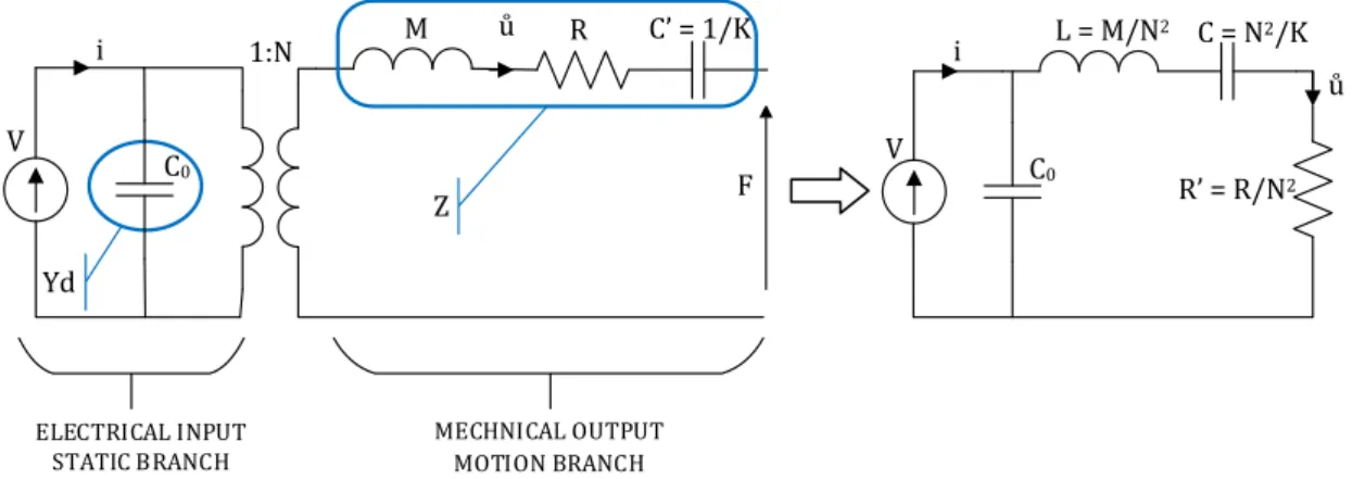
4.1 Modeling of the resonance structures. General remarks ... 39
4.2 Equivalent circuits... 40
4.3.3 Langevin’s transducer ... 50
4.4 Rotating-mode motor ... 54
4.4.1 Equivalent circuit for metal-cylinder ... 54
4.4.2 Stator kinematics ... 56
4.4.3 Torque vs. speed characteristic ... 58
4.5 Preliminary dimensioning and analysis of the prototype MPM ... 60
4.6 Conclusions ... 66
5 Simulations of the prototype MPM ... 67
5.1 Finite element method ... 67
5.2 Piezoceramic structure ... 69
5.3 Counter-mass ... 70
5.3.1 The first structure of the actuator ... 71
5.3.2 The second structure of the actuator ... 74
5.3.3 The third structure of the actuator ... 75
5.4 Rotor ... 77
5.5 Conclusions ... 79
6 Manufacturing and measurements of the prototype MPM ... 80
6.1 Motor parts manufacturing ... 82
6.1.1 Polarization process of the piezoceramics ... 82
6.1.2 Motor parts preparation... 86
6.2 Resonance frequency measurements of the preliminary structure ... 89
6.3 Displacement measurements ... 92
6.4 Resonance frequencies measurements of the final structure ... 94
6.5 Torque vs. speed characteristic measurements ... 95
6.5.1 A concept of power supply for piezo structures... 96
6.5.2 A simplified system for supply and measurements ... 97
6.5.3 Power supply and measurements system using dSpace laboratory stand ... 99
6.6 Conclusions ... 104
7 Final conclusions ... 105
7.1 Research results and the dissertation achievements ... 105
7.2 Future research works ... 106
Appendix 3 ... 138 Appendix 4 ... 139 Appendix 5 ... 140
1 *The project is co-financed by the European Union within the European Social Fund – Human Capital
Operational Programme (HC OP).
1
G
ENERAL INTRODUCTIONS
he modern applications of mechatronic/electromechanical motion systems feature increasing integration of motor (actuator), and sensor functions within a coupling mechanism. This tendency is especially advanced in the field of motors (actuators) characterized by centimetric or decimetric dimensions. It opens an area to design a new generation of electromechanical motion devices which are capable to take up the challenge of the tendency to the more open electrical technology (MOET). In different fields of technology such as: automotive, e.g., engine controlling systems, driving comfort; bio-medical engineering, e.g., driven prostheses, robotized micro-surgery; smart houses and building; avionics and aeronautics, e.g., actuators for flight control, actuators for energy sources system management. [43], [44], [69], [70]. Achieved recently progress in the field of materials engineering, whether passive materials (composite magnetic materials) or smart (intelligent materials)/electroactive (piezoelectric, electrostrictive ceramics, magnetostrictive alloys, shape memory alloys) supports a very promising field of innovations with a very high level of functional integration of mechatronic/electromechanical motion systems [45], [53], [73].
The piezoelectric motors (actuators) are relatively new in comparison to the motors using electromagnetic structures. The results, obtained in the field of piezoelectric motors, have pointed out that these motors have potentially high possibilities in the forthcoming special and advanced applications. The piezoelectric motors (actuators) feature interesting properties in terms of torque per mass ratio. In general, their torque is 10 – 100 times higher than the electromagnetic motors (actuators) of the same size or same weight.
Applications of the piezoelectric motor (actuator) reduces the number of gears due to coupling it directly to the power train shaft. As a result a better efficiency of the electromechanical motion system is gained . In turn, for positioning application, where a high blocking torque is required, particularly the multi-piezoelectric motors (actuators) seems to be the most suitable.
In this dissertation new concept of a multi piezoelectric motor dedicated to adjust the position of car seats has been considered.
1.1
O
BJECTIVES OF THIS DISSERTATIONThe research work described in this dissertation has been conducted as part of the European Union sponsored programme ERASMUS [91], and project called The Center for Advanced Studies - the development of interdisciplinary doctoral studies at the Gdansk University of Technology in the key areas of the Europe 2020 Strategy, referred to as Advanced PhD* [92]. The research works has been carried out with the cooperation between the INP - ENSEEIHT - LAPLACE (Laboratory on Plasma and Conversion of Energy), in Toulouse, France, and the Gdańsk University of Technology, Faculty of Electrical and Control Engineering, Research Unit Power Electronics and Electrical Machines, Gdańsk, Poland [90].
2 The Laboratory LAPLACE is an interuniversity research unit and is involved in advanced research programs in the following fields: technological plasmas and their applications, transport phenomena, dielectric materials (particularly polymers) and their integration into systems, design of electrical systems, optimization of control systems and converters [89]. One of the Laboratory LAPLACE’s research group – GREM3 – is a leading research unit in the world in the field of piezoelectricity and shape-memory alloys technology.
The first part of the 12 months studying and research programme in the frame of ERASMUS started in September 2011 at the INP-ENSEEIHT-LAPLACE. This programme in the frame of "Transformation de l'Energie et Mécatronique avancée" covered issues of power electronics, automation and mechatronics systems, and has been completed with the Master International research project and diploma. The first part of the carried out research covered the “Rotating-mode motor – simulations, manufacturing and measurements”, and also the “Hybrid piezoelectric motor”. In turn, the second part: six months Master International research project has been called “Moteur piézoélectrique multicellulaire”.
The second part of the 10 months research programme in the frame of the Advanced PhD started in October 2013 and has been divided into 7 months research work carried out at the Research Unit Power Electronics and Electrical Machines, and 3 months internship at the Laboratory LAPLACE. The subject of the research work conducted at the Laboratory LAPLACE was "Multicell piezoelectric motor" and has covered measurements and analysis of the performance characteristics of the prototype multicell piezoelectric motor.
It should be underlined that the research works in the field of piezoelectric technology have not been carried out on a wide scale in Poland, so far. The research works conducted in the frame of this disseration are one of the pioneer research works in Poland, that focuses on application of piezoelectric phenomenon to design and manufacture piezoelectric motors (actuators).
The thesis of this dissertation is following:
Multicell piezoelectric motor based on the concept of a combined topology using the working principles of the traveling wave motor,
and the electromechanical structure of the rotating-mode motor
is characterized by a relatively high values of the rotating speed and blocking torque, respectively.
To describe in systematic way the development of modeling, design, measurement, and manufacturing (implementation) technology for new concept multicell piezoelectric motor the dissertation has been structured as follows.
The chapter 2 describes the piezoelectric phenomenon, piezoelectric materials, structures of piezoelectric motors (actuators).
The chapter 3 briefly describes the presently applied servo drives for the control of the car seat position. Next, the known structures of the multi piezoelectric motors have been considered in view of their applications for car seat adjustment. Finally, a general introduction to prototyping
3 a novel concept multi piezoelectric motor, referred to as "multicell piezoelectric motor" (MPM), have been presented.
The chapter 4 contains a description of analytical approach to modeling the basic structures of piezoelectric motors (actuators). First, modeling of the resonance structure using the Mason’s equivalent circuit has been explained. Next, the principle and the basic relationships involved in the Langevin’s transducer and rotating-mode motor have been described. Moreover, the rotating-mode motor stator kinematics has been presented, since there is a difference between the excited mode of the rotating-mode motor and the Langevin’s transducer. Finally, using the Langevin’s transducer equivalent circuit, the analytical model of the MPM has been developed and implemented in the Matlab software. The MPM developed model is based on properly modified known analytical model of the rotating-mode motor. The MPM preliminary dimensions and parameters have been determined using the developed analytical model.
In chapter 5 the preliminary dimensions and parameters of the prototype MPM have been verified using its virtual (geometrical) model and developed FEM model. Using the FEM model of the prototype MPM the resonance frequencies and stress values have been determined.
In chapter 6 manufacturing process, assembling and experimental verification of the prototype MPM has been described.
Finally, the last chapter describes the final conclusions: research results and the dissertation achievements, and future research works.
4
STRUCTURES
n the first part of this chapter the piezoelectric phenomenon has been explained and the piezoelectric materials have been described as well. In the second part the main topologies of the piezoelectric motors have been presented.
Piezoelectricity is widely used in industrial sectors such as the production and detection of sound, generation of high voltages, electronic frequency generation, microbalances, driving an ultrasonic nozzle and ultrafine focusing of optical assemblies. It is also the basis of a number of scientific instrumental techniques using atomic resolution e.g. the scanning probe microscopies such as a scanning tunneling microscope (STM), atomic force microscopy (AFM), microthermal analysis (MTA), near-field scanning optical microscopy (NSOM/SNOM) etc. It can be found useful in everyday life activities, such as acting as an ignition source for lighters.
2.1
P
IEZOELECTRIC PHENOMENASome materials combine electromagnetic and mechanical properties that interact with each other even within these materials [39]. Thus, they have an intrinsic electromagneto-elastic coupling properties that can be used to build up electromechanical transducers, i.e., motors and actuators [65].
Historically, the phenomenon of magnetostriction (1847) was discovered before piezoelectricity (1881) by James Joule [27]. He discovered that a ferromagnetic material changed its length with the application of magnetism. The development of the new materials (especially rare earth element) has resulted in discovered the new phenomenon.
The first research work on piezoelectricity has been done by Carl Linnaeus and Franz Aepinus in the mid-18th century [2], [33]. They studied the pyroelectric effect, by which material generates an electric potential in response to a temperature change. Based on this knowledge, both René Just Haüy and Antoine César Becquerel posited a connection between mechanical stress and electric charge. However both experiments were found unconvincing [76].
Fig. 2.1 An illustration of piezoelectric effect a) direct b) inverse [59]
The first phenomenon is called the direct piezoelectric effect. The name “piezoelectricity” was given by Wilhelm Gottlieb Hankel [28]. When mechanical force or pressure is applied to piezoelectric material, the electric charge or voltage is induced on the surface (Fig. 2.1a).
I
5 Conversely, if some charge or voltage is imposed on a piezoelectric material, the material reacts by generating some mechanical force and strain. This phenomenon is called the converse piezoelectric effect (Fig. 2.1b). Pierre and Jacques Curie show in 1881, the direct piezoelectric effect. A year later, Pierre and Jacques Curie, basing on the work of Lippmann, demonstrated the existence of an inverse effect [4], [12]- [13], [34].
The first commercial application of the inverse piezoelectric effect was the sonar system during the First World War [73]. In 1917, Paul Langevin used a piezoelectric material (quartz) to detect the presence of submarines. The sonar consisted of a transducer, made of thin quartz crystals glued between two steel plates, and a hydrophone to detect the returned echo-signal. By emitting a high-frequency pulse signal from the transducer, and measuring the value of time it takes to hear a signal from the sound waves bouncing off an object, one can calculate the distance to that object. Materials used then, (quartz, tourmaline, Rochelle salt, etc.) revealed weak piezoelectric features. The need to produce materials with improved performance has led to the invention of ceramic polycrystalline [6].
In 40’s, during World War II, in the United States, USSR, and Japan discovered a new class of synthetic materials. It was called ferroelectrics. Piezoelectric properties raise when exposing it to an electric field polarization due to the many times higher piezoelectric constants than natural materials. This helps to intense research and develop a barium titanate and later a lead zirconate titanate materials with specific properties for particular application. Barium titanate and plumbum zirconate titanate, have been named with the acronym PZT. Nowadays, the piezoelectric phenomenon is used in several areas such as sensors, actuators, positioning, detection of seismic zones, igniters, microphones, etc.. The PZT ceramics are most commonly used for piezoelectric motors [3].
Tab. 2.1 Major applications of piezoelectricity [76]
Communications and control
Industrial Health and consumer Newer applications Cellular radio Television Automotive radar Sensors Actuators Pumps Motors Transducers Sensors Actuator Smart Structures High Displacement Transducers Mixed-effect Device o Signal processing o Frequency control and timing o Correlators o Convolovers o Filters o Delay lines o Oscilators o Ultrasonic cleaning sonar o Nondestructive evaluation (NDE),
o Liquid level sensors
o Vibration damping o High temperature sensors o Material properties determination o Chemical/biological sensors o Noninvasive medical o diagnostics Hyperthermia Lithotripsy o Subcutaneous medication o Wristwatches o Camera focusing /steadying / ranging o Computer timing / printing / modem o Ignition of gases (“spark pump”) o Microelectromechanical (MEMS) devices o Microoptomechnaical (MOMS) device o Biomimetic devices o Composite and functionally graded devices o Rainbow devices o Acousto-photonic-electronic devices
6
2.2
P
IEZOELECTRIC MATERIALSAs was written in previous chapter, the first mineral which established the piezoelectric effect was quartz. Quartz (Fig. 2.2) is the second most abundant mineral in the Earth's continental crust, after feldspar. The technological progress allowed to increase the material’s properties. The technology of cuts (SC - Stress Compensated developed in 1974) improved the sensitiveness to mechanical stresses and increased temperature transient effects. Working frequencies ranged from below 1 kHz to above 10 GHz [76].
Two types of quartz crystals exist: left-handed and right-handed. This two types differ in the optical rotation but they are identical in other physical properties. If the cut angle is correct, both left and right-handed crystals can be used for oscillators. In manufacture, the right-handed quartz is commonly used. Quartz exists in several phases. At 573 °C at 1 atmosphere (and at higher temperatures and higher pressures) the α-quartz undergoes quartz inversion, transforms reversibly to β-quartz. The reverse process however is not entirely homogeneous and crystal twinning occurs. Special attention is recommended during manufacture and processing to avoid the phase transformation. Other phases, e.g. the higher-temperature phases of tridymite and cristobalite, are not significant for oscillators. All quartz oscillator crystals are the α-quartz type [15], [21].
a) b)
Fig. 2.2 a) Right-hand quartz, showing natural facets b) Cluster of natural quartz crystals [76]
The application where quartz was used are: resonators, filters, delay lines, transducers, sensors, signal processors, and actuators.
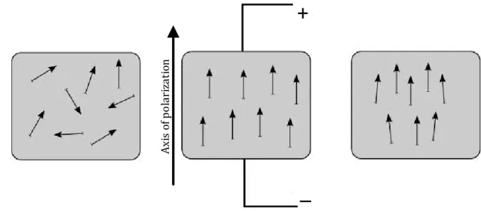
Nowadays, the piezoelectric ceramics are produced mainly from zirconate titanate (PZT). Ceramic materials have several advantages over single crystals, especially the ease of manufacturing in a variety of shapes and sizes. In contrast, single crystals must be cut along certain crystallographic directions, what limits the possible geometric shapes. A piezoelectric ceramic material consists of small grains (crystallites), in which the polar direction of the unit cells are aligned. Before polarization, these grains and the areas are oriented randomly, so that the overall polarization of the material is zero. Therfore, the piezoelectric ceramics do not exhibit piezoelectric properties. The application of a sufficiently high field (called polarization process), will collocate electric potential of the crystal grains similarly to the direction of the
7 field. When the remnant polarization is used, then the material exhibits a piezoelectric effect (Fig. 2.3 and Fig. 2.4). The piezo polymers polyvinylidene fluoride (PVDF or PVF2) are a special class of fluoropolymer that have a high level of piezoelectric activity. They are used to produce piezoelectric thin films (less than 30 microns), which can be laminated on the structural material [4], [76]. Ax is o f p ol ar iz at io n
+
_
Fig. 2.3 Electric dipoles in the piezoelectric materials before, during and after polarization.
2.2.1
T
EMPERATURE LIMITSImportant issue that should be considered is a Curie temperature. It is a point which corresponds to the temperature where the material loses his piezoelectric qualities due to the excessive agitation of the molecules. This point is very relevant because it severely limits the operating temperature of piezoelectric ceramics. In general, piezoelectric ceramics are properly working in the half of the Curie temperature [8].
The following describes the Curie Temperature for a few selected materials: SiO2 ≈ 573°C,
LiNbO3 ≈ 1210 °C, BaTiO3 ≈ 130°C, PVDF ≈ 180°C, PZT ≈ 350°C.
The parameter relevant for the piezoelectricity is also temperature sensitiveness and more particularly the relative permittivity, which varies in an order of magnitude of 5·10-3 per one degree for PZT [26], [78].
2.2.2
V
OLTAGE LIMITSThe voltage limit of the piezoelectric ceramic depends on the level of electrical field applied. If imposed electrical field is too high, ceramic is depolarized, losing the piezoelectric properties.
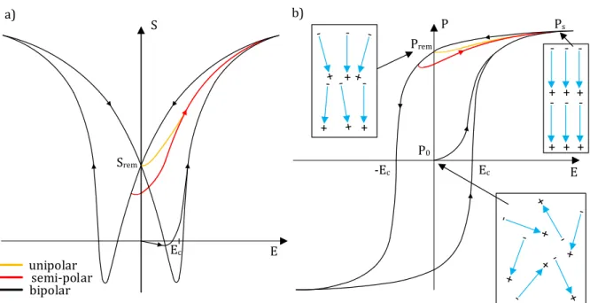
8 S P Prem E E Srem E c -Ec -+ -+ -+ -+ -+ -+ Ec + -+ a) b) unipolar semi-polar bipolar P0 Ps
Fig. 2.4 a) Electromechanical behavior of the longitudinal strain S b) dielectric behavior of the polarization P
Before the first polarization, the electrostatic dipoles are deployed randomly in the material so the polarization of the internal field of ceramics (point P0) is zero. During the polarization
process, the material passes successively from zero to maximum polarization (point Ps). After
the polarization the point is set on the phase of remnant polarization (point Prem), which has
been shown in Fig. 2.4.
2.2.3
P
RESSURE LIMITSThere are two types of pressure limits. The first one, is the depolarization where the internal electric field in the ceramic is greater than the depolarization field which causes a depolarization of the ceramic. The second limit, is the limit where mechanical pressure or high excessive force causes a deterioration of the ceramics. The pressure limit is more important than the yield strength (generally by a factor of 10), which explains that the piezoelectric ceramics generally work under preloading [5].
2.3
P
IEZOELECTRIC CONSTITUTIVE EQUATIONSThe nature of the piezoelectric effect is closely related to the occurrence of electric dipole moments in solids. The piezoelectric phenomenon is manifested by the conversion of electrical energy into mechanical energy and vice versa [72]. When an electric field (E) and a field of mechanical stress (T) are applied to the piezoelectric materials, two things happen:
• mechanical deformation S which can present itself as a translation or rotation respectively along the axes x, y and z.
9 Piezoelectricity is the combined effect of the electrical behavior of the material and Hooke’s Law [25]:
𝐷𝑛 = 𝜀𝑛𝑚𝐸𝑚
𝑆𝑗= 𝑠𝑖𝑗𝐸𝑇 𝑗
(2.1) At the beginning of the most important factors will be presented:
Sij is the strain tensor (m)
Tij is the stress tensor (N/m2)
Ei is the electric field vector (V/m)
Di is the electric displacement field vector (C/m2)
εij is the permittivity tensor (F/m)
βij (ε-1) is the impermittivity components tensor (m/F)
cijkl is the elastic stiffness constant tensor (N/m2)
sijkl (c-1) is the elastic compliance constant tensor (m2/N)
The s and c are obtained in the absence of electric field (E = 0) or charge (D = 0). Although, the ε and β obtained in the absence of mechanical strain (S = 0) or stress (T = 0).
Constitutive equations of piezoelectric materials for one medium dimension could be written as the tensorial representation of the strain–charge displacement form:
𝑆𝑖𝑗= 𝑠𝑖𝑗𝑘𝑙𝐸 𝑇
𝑘𝑙+ 𝑑𝑘𝑖𝑗𝐸𝑘
𝐷𝑖 = 𝑑𝑖𝑘𝑙𝑇𝑘𝑙+ 𝜀 𝑖𝑘𝑇 𝐸 𝑘
(2.2) In general the piezoelectric materials have 21 independent elastic constants, 18 independent piezoelectric constants and 6 independent dielectric constants [25]:
eijk is the piezoelectric constant for stress-charge (N/m2)
dijk is the piezoelectric constant for strain-charge (m/V or C/N)
gijk is the piezoelectric constant for strain-voltage (Vm/N or m2/C)
hijk is the piezoelectric constant for stress-voltage (V/m N/C)
Other forms of the constitutive equations are: stress-charge: 𝑇𝑖𝑗 = 𝑐𝑖𝑗𝑘𝑙𝐸 𝑆𝑘𝑙− 𝑒𝑘𝑖𝑗𝐸𝑘 (2.3) 𝐷𝑖= 𝑒𝑖𝑘𝑙 𝑆𝑘𝑙+ 𝜀𝑖𝑗𝑆𝐸 𝑘 strain-voltage: 𝑆𝑖𝑗= 𝑠𝑖𝑗𝑘𝑙𝐷 𝑇 𝑘𝑙+ 𝑔𝑘𝑖𝑗 𝐷𝑘 (2.4) 𝐸𝑖 = −𝑔𝑖𝑘𝑙 𝑇𝑘𝑙+ 𝛽𝑖𝑘𝑇 𝐷 𝑘
10 stress-voltage: 𝑇𝑖𝑗= 𝑐𝑖𝑗𝑘𝑙𝐷 𝑆 𝑘𝑙− ℎ𝑘𝑖𝑗 𝐷𝑘 (2.5) 𝐸𝑖 = −ℎ𝑖𝑘𝑙 𝑆𝑘𝑙+ 𝛽𝑖𝑘𝑆 𝐷 𝑘
Indexes i, j = 1, 2, 3, …, 6 and k, l = 1, 2, 3 are different directions within the material coordinate system shown in Fig. 2.5.
And matrix form:
[𝑆𝐷] = [𝑠𝐸 𝑑𝑡
𝑑 𝜀𝑇] [𝐸𝑇] (2.6)
Furthermore, [d] is the matrix for the direct piezoelectric effect and [dt] is the matrix for the
converse piezoelectric effect. First elements after the equations refer to the mechanical properties of an elastic body and to electric properties of a dielectric medium. Artificial piezoelectric materials obtain remnant polarization in the process of poling [6], [72].
2.4
C
OUPLING FACTOR/
COEFFICIENT AND DIFFERENT MODESThe ability of a transducer to convert the energy is characterized by the coupling factor k [74]. It characterizes the quality of the electro-mechanical conversion in the piezoelectric material and therefore the ability of the oscillator to convert electrical energy into mechanical energy. Considering the density of mechanical energy WM, electrical energy WE and electromechanical
energy WEM, k is defined as:
𝑘 = √ 𝑊𝐸𝑀
2
𝑊𝐸∙ 𝑊𝑀 (2.7)
In the case of an energy conversion involving only the piezoelectric material, the coupling coefficient can be expressed in terms of electromechanical material parameters and by mode of deformation considered by:
𝑘𝑖𝑗 = √ 𝑑𝑖𝑗
2
𝜀𝑖𝑖𝑇 𝑠 𝑗𝑗𝐸
(2.8) Artificial piezoelectric materials acquire a remnant polarization through the process of polarization. The direction of polarization is the direction of electric field. This direction is marked by convention, the Z-axis orthogonal system x, y, z (Fig. 2.5). The indexes 1, 2 and 3 are linked to these axes, respectively. Indices 4, 5, and 6 are used to describe the shear identified in the directions 1, 2 and 3. Modes couplings can then be defined theoretically by constants with two indices. The first index i in coupling factor corresponds to the direction of the applied electric field, and second j is the axis where deformation take place [30], [40].
11
Z (3)
Y (2)
X (1)
6
5
4
Po
la
ri
za
ti
on
a
xi
s
Fig. 2.5 Modes of the piezoelectric material [62]
As was stated the piezoelectric ceramics are characterized by electromechanical coupling coefficient k. The direction of deformation can be done in several directions that can be classified in three main ways (Tab 2.1):
1. the longitudinal mode (mode 33), results in a change in length along the axis 3, when an electric field is applied along the same axis by means of electrodes placed on the sides perpendicular to this axis,
2. the transverse mode (mode 31 or 32), leads as well to a change in length along the axis 1 when an electric field is applied along the axis 3,
3. shear mode (mode 15), leads to a shear deformation around the axis 2 when an electric field is applied along the axis 1.
The movement depends on the geometry and the relative orientation of the crystal axes and the position of the electrodes. Electrical field has an elongation in that direction and contraction in the perpendicular direction. The reverse field causes contraction in the direction of the field and an elongation in the perpendicular direction. The d33 mode provides three times stronger
12
Tab. 2.1 Different modes of coupling in piezoelectric materials Longitudinal mode 𝑆3= 𝑠33𝐸 𝑇3+ 𝑑33𝐸3 𝐷3= 𝑑33𝑇3+ 𝜀33𝑇 𝐸3 𝑘33= √ 𝑑332 𝜀33𝑇 ∙ 𝑠 33𝐸 3 2 1 E P0 Transverse mode 𝑆1= 𝑠11𝐸 𝑇 1+ 𝑑31𝐸3 𝐷3= 𝑑31𝑇1+ 𝜀33𝑇 𝐸 3 𝑘31= √ 𝑑312 𝜀33𝑇 ∙ 𝑠 11𝐸 3 2 1 E P0 Shear mode 𝑆5= 𝑠44𝐸𝑇 5+ 𝑑15𝐸1 𝐷1= 𝑑15𝑇5+ 𝜀11𝑇 𝐸 1 𝑘15= √ 𝑑15 2 𝜀11𝑇 ∙ 𝑠 44𝐸 3 2 1 5 E P0
On the Tab. 2.1 the properties of some piezoelectric material samples have been presented. Following the values from the table, the coupling factor k33 is the most relevant in terms of
13
Tab. 2.1 PTZ material properties samples [79], [80]
2.5
R
ESONANCE MOTORSModern piezoelectric motors/actuators are generally built using either quasi-static or resonance operating topologies. There are several types of those piezoelectric motors – traveling wave motor, rotation mode motor, quasistatic motor - but they all have a similar principle of operation. When they work in a step by step mode those structures rarely generate rated torque greater than tens of Nm. However, they exhibit interesting properties in terms of torque per mass ratio and relatively small dimensions compared to electromagnetic motors. The detailed comparison of those structures will be discussed in the following paragraphs [7].
In Fig. 2.6 it is shown the classification of motor/actuators technologies according to the force vs. velocity characteristics. Electroactive motors/actuators which have the highest energy density are based on the piezoelectric ceramics or magnetostrictive ceramics [45].
Model Type Coupling factors
Curie Temperature [°C] Piezo charge coefficients [10-12 C/N] Dielectric constants (1 kHz) k15 k33 k31 d33 ε33 PZT-4D Soft PZT 0.62 0.71 0.33 310 360 1280 PZT-8 Hard PZT 0.57 0.68 0.34 320 280 1000 P189 Traditional Hard PZT 0.51 0.65 0.32 320 240 1150 P762 Traditional Hard PZT 0.58 0.68 0.35 300 300 1300 P188 Traditional Soft PZT 0.62 0.75 0.37 340 425 1850 Pz27 Traditional Soft PZT 0.59 0.70 0.33 350 425 1800 Pz37 Low-Acoustic Impedance Family 0.35 0.60 0.15 370 350 1150 Pz46 High Temp PZT 0.03 0.09 0.02 650 18 120
14
Fig. 2.6 Comparison of the various electromechanical effects in terms of specific energy [45], [53]
Piezoelectric motors are based on the conversion of mechanical high-frequency oscillations (tens of kHz) in a continuous movement and are interesting for applications where the functional integration, and reduced mass are required. Piezoelectric materials can be used as oscillators (quartz crystal), and in the case of piezoelectric motors, usually PZT ceramics are implemented [44], [67]. An ultrasonic motor is a transducer where a mechanical vibration in the ultrasonic wave range is used as its driving source.
The advantages of piezoelectric motors are following: high torque, high resolution, excellent control, a small time constant, compactness, high efficiency, quiet operation, and no electromagnetic field. In Fig. 2.7 the principle operation of an traveling wave motor (flexural traveling wave ring-type motor) is shown as an example. Using a resonance mode of the mechanical structure enables the transformation of micro displacements and movement to large amplitudes. FN FT STATOR ROTOR COATED WITH FRICTIONAL MATERIALS FN (NORMAL FORCE) FT (TANGENTIAL FORCE) TRAVELING WAVE RESONANT STRUCTURE HOUSING ELLIPTICAL MOVEMENT V = 0.5 ms-1 F < 100 KHZ ROTOR STATOR
15 Generally the piezoelectric motors/actuators are composed of four parts: stator, rotor, piezoelectric ceramics and power supply. The stator consists of piezoelectric material associated with a mechanical structure. Piezoelectric material structures are properly supplied by a two-phase source of voltage and therefore deformed at a frequency corresponding to the mechanical resonance frequency of the structure to which they are associated by adhesive bonding or preload. Thus, the initial deformation of ceramics is amplified by the effects of the resonance of the mechanical structure. Stator’s final deformation is sinusoidal and is gradually becoming the two-phase supply areas of ceramics. The rotor is a mechanical part, which is held in contact with the stator by a constraints (screw).
The point trajectory of contact between the stator and the rotor is described by an ellipse. This ellipse can be modeled by a wave of the form:
𝑢 = 𝐴𝑐𝑜𝑠(𝑛𝜃 + 𝜔𝑡) (2.9)
Where ω is the vibration frequency, θ is phase angle and A is vibration amplitude. A traveling wave may result from the sum of two standing waves [41]:
𝑢 = 𝑢1+ 𝑢2= 𝑉𝑠𝑖𝑛(𝜔𝑡)·𝑠𝑖𝑛(𝑛𝜃) + 𝑉𝑐𝑜𝑠(𝜔𝑡)·𝑐𝑜𝑠(𝑛𝜃) (2.10)
The elliptical motion is decomposed into two components:
normal, which controls the frictional force by compensating the axial force applied by a spring FN on the moving part,
tangential, which induces the driving force expressed by Coulomb's law FT = FN.
2.5.1
U
LTRASONIC MOTORSIn office equipment such as printers and disk drives, market research indicates the potential application of motors with a volume of 1 cm3 [35], [74]. Ultrasonic motors have better properties compare to classical electrical motors – torque/mass ratio and high resolution. The principle of operation of the motor is based on the wave generation on the stator by a piezoelectric ceramic ring (usually it is lead zirconium-titanate-compound – PZT) glued to the back of the drive ring. The operation depends on friction at the interface between the moving rotor and stator. To extended lifetime of the motor, a design of the specific and precision construction of the stator is necessary [3], [23].
16 COVER STATOR PIEZOELECTRIC CARAMIC SPRINGS SHAFT ROTOR
Fig. 2.8 Exploded view of a ultrasonic motor [81]
The stator has ring type construction with teeth on it. Teeth are arranged in a ring at the radial position and are intended to form a moment arm to amplify the amplitude of displacements, so increasing the speed. To generate a traveling wave within the stator two orthogonal modes are activated simultaneously. The rotor is driven by friction. This type of motor uses specific kinematics at the level of interface between the rotor and stator. Produced forces are a priori weaker. The points at the rotor/stator contact surface are oscillating in an elliptic way. Generally, the stator is made of beryllium-copper and the rotor from duralumin (Fig. 2.8) [32], [64].
-+
+
+
+
+
+
+
+
Phase 2
Phase 1
λ
λ/4
3λ/4
-+
-
P
Fig. 2.9 Sectorization of a piezoelectric ring in ultrasonic motor [42]
There are two sets of electrodes, each having eight sectors of width λ/2. The second set is shifted
λ/4. These modes are induced by a stator that is constructed with the drive piezoelectric
actuators in the form of two sections of poling pattern that are bonded to the stator. Geometrical examination of this pattern shows that driving the two sections using sin(ωt) and cos(ωt) supplying signals, respectively, will produce a traveling wave with a frequency of ω/2p. Also, by
17 changing the sign on one of the drive signals, the traveling wave would reverse its direction (Fig. 2.9) [22].
The advantages of travelling wave motors are following: silent operation due to excitation in a field of inaudible frequencies (>20 kHz), relatively low speed (requiring no gear) and short response times (a few ms) at startup and braking provide excellent dynamic control position or speed. Another advantage is torque/mass high ratio (>10 Nm/kg). In this kind of stator structure appears a technological problem, because the bond between the ceramic and the metal is provided by a glue joint [11], [46].
Canon was one of the pioneers of the ultrasonic motor (motor annular wave - USM) [82]. The motor is used to controlling the auto focus - AF (Fig. 2.10). Camera’s autofocus lenses are driven by these small piezoelectric motors. The stator of this motor is composed of a metal ring which is bonded on a ceramic PZT exciting a bending mode of row 9. The rotor is driven by friction at nine sliding contact points (nine traveling wave are generating). The ring-type USM is actually very simple in operation and interesting in terms of integration within the autofocus. By applying a AC signals with a resonance frequency about 40 kHz to the structure, vibrations are created, causing the rotor is rotate continuously. Depending on the model, Canon uses three types of ultrasonic motor: ring type, micro USM I and II with a gear unit.
RING-TYPE USM MICRO USM MICRO USM II GEAR UNIT GEAR UNIT
18
2.5.2
R
OTATING-
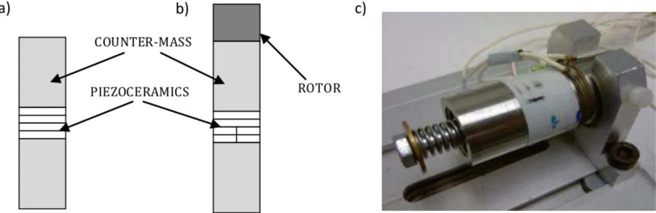
MODE MOTORThe rotating-mode motor (Fig. 2.11) consists of the same parts as a Langevin type transducer, which is basically composed of one or more pairs of piezoceramic rings sandwiched between two metal counter-masses (stator). In addition, the rotating-mode motor has one or two rotor [42].
a) b) c)
COUNTER-MASS
PIEZOCERAMICS ROTOR
Fig. 2.11 The structures of the: a) Langevin’s transducer b) rotating-mode motor c) rotating-mode motor prototype (LAPLACE Laboratory)
The difference is in the excited mode: in rotation-mode motor the mode of flexion exists, whereas Langevin type transducer - longitudinal vibration modes. The stator of a rotating-mode motor uses two modes of bending (Fig. 2.12). The ceramics are discs with opposing polarization on each half. The whole structure is prestressed by a screw.
Sin(ωt) Cos(ωt) α β Fn Sin(ωt) Cos(ωt)
Fig. 2.12 Operation principle of a rotating-mode motor [42]
The two sinusoidal high frequency phase shifted voltage sources are used to supply the ceramics structures. The ceramics are oriented at each other by 90° (Fig. 2.13). Following this conditions, the traveling wave is generating. The traveling wave is amplified by the counter-mass. Generated
19 traveling wave is in contact with the rotor on the stator in any time. The rotor (like in ultrasonic motor) is driven by friction [66].
POLARIZATION DIRECTION
Ucos(ωt)
Usin(ωt)
90˚
Fig. 2.13 Piezoceramics arrangement in rotating-mode motor [10]
The main advantages are the high torque to mass ratio (10 N/kg), a blocking torque, small number of parts (simple structure) and low weight .
A good example of this motor type is the piezoelectric rotating mode motor with high torque density developed in LAPLACE Laboratory in Toulouse. The project was carried out with cooperation between Airbus and LAPLACE in Toulouse. The goal was to create a new concept of piezoelectric rotation mode actuator with high torque density and that is dedicated in aeronautical application areas. The project name was “Future Flight Control” [70] – [72].
For the above case the rotating-mode motor structure is suitable to use because it has simple design and possibility to adjust the preload to piezoceramics to maximize their potential. Other advantage is rotor/stator contact on the entire surface. To increase the properties of the actuator the second rotor has been used due to symmetrical structure. In addition the uses the double rotor it is possible to obtain better force control. The counter-mass (stator) has been made from aluminum alloy AU4G type, to reduce the weight of the actuator. Moreover, this material allows to reduce the mechanical losses comparing to steel. The rotors were made of steel, because the material of high density was necessary. The rotor should have sufficient inertia to ensure the proper functioning of the electromechanical power conversion process. The hard ceramics of the type PC8 have been used because they do not generate much losses. The virtual prototype is presented in Fig. 2.14, and real model parts are shown in Fig. 2.15.
20
STATOR
ROTOR
SHAFT
FIXING
Fig. 2.14 The virtual prototype of the piezoelectric rotating-mode actuator with high torque density [72]
b) STATOR a) ROTOR
Fig. 2.15 The actuator parts: a) rotor, b) stator [72]
The obtained performance characteristics have shown a very interesting technological solution, i.e., the torque density was approximately 8 Nm/kg. The obtained parameters of the prototype for the supply voltage 780 V (rms) was following: velocity 52 rpm, blocking torque 4.2 Nm. The mechanical power of the actuator was around 6 W.
In addition, to supply the above motor, a dedicated frequency converter of 400 Hz and 200/115 V/V was designed (Fig. 2.16). The system has been built and tested in the laboratory with the static converter for the effective application of two voltages 600 V phase-shifted by 90° at a frequency of approximately 20 kHz [71].
21
TRANSFORMER
INDUCTANCE FILTER
AC INVERTER
Fig. 2.16 Power supply of the rotating-mode motor with high torque density [71]
2.6
O
THER PIEZOELECTRIC MOTOR/
ACTUATOR STRUCTURES2.6.1
Q
UASI STATIC ACTUATORSThe principle operation of the quasi static actuators is based on the deformation of ceramics (Fig. 2.17), such as multilayer ceramics, of the order of a few microns, which are supplied with the low frequencies (below few hundreds of Hz). The multiplication of these micro displacements results in movements of larger amplitudes. This type of motors is used primarily for their nano displacement, precision and substantial generated forces. Moreover, the used kinematics is a solid and low speed ( 3÷10 mm.s-1). Thus, the contact imposes the coefficient of a static friction. This kind of motor usually consists of three parts: clips, gripers and piezoceramics changing distance between two previous parts [18], [63], [69].
22 The operating cycle is divided into several steps (Fig. 2.18):
1. the two grippers are gripping the guide,
2. the first gripper is released while another continues gripping the guide,
3. the actuator is extending to move the free gripper, the second gripper is fixed still, 4. then actuator reach the maximum the first gripper is going to fix,
5. the second actuator is released,
6. the actuator is shortening to move the second gripper,
7. when actuator reach the minimum the second gripper is going to fix.
1
2
3
4
5
6
7
Grippers
Piezoelectric stack
23 Quasi-static structures (Fig. 2.19) have some advantages: like high step resolutions which is useful for micropositioning applications, and high torque/mass density. However, they have limited power and low speed.
For the dedicated applications the quasi-static structures have been chosen to implement modification of the operating principle to overcome recurring problems of conventional structures (sensitivity to wear, poor accommodation surfaces). The electroactive lubrication between rotor and stator is also added (using the resonance piezoactuators), in order to disengage rotor and stator in the return phase.
A combination of these two topologies, i.e., using hybrid topology, can result in further advantages of piezoelectric motors. The considered hybrid piezoelectric motor is characterized by much more compact dimensions and lower weight. It exhibits higher torque per volume ratio as well as good blocking ability when is not powered. It operates at a low speeds and do not require any gear reduction system which leads to further gains in weight and volume. Finally, it can work in higher temperatures compared to the variable reluctance motor. On the other hand, while using the piezoelectric elements there is a risk of depolarization as well as a shorter life span.
a)
b)
Fig. 2.19 Quasi-static operating piezoelectric actuator: a) conception, b) prototype [53]
2.6.2
E
LECTROACTIVE LUBRICATION PRINCIPLEThe main idea using the electroactive lubrication is to control the friction forces between the rotor and stator [54]. By the vibrations (µm amplitude, a few kHz frequency) injected at the dry contact between two pieces, subjected to a certain relative speed, the frictional forces resulting from the movement between the two solid bodies are decreased. To increase motor efficiency, it is necessary to reduce the friction losses as low as possible. While keeping power consumption as low as possible it is possible to obtain a relatively high speed and vibration parameters (amplitude and frequency) [54].
24 The principle of electroactive lubrication is based on the control of the friction forces. To obtain this goal the injection of vibrations into the contact surface between rotor and stator is used. The friction control process can be divided in two main stages (Fig. 2.20):
Contact surfaces are separated if the proper vibration magnitude is injected. For this state (indicated by interval t1) there is no friction (friction force - Ffr = 0)
Upon contact of the surfaces, the two bodies have to be in the state of partial slip. While there is a full slip, the entire contact surface slides (the state is indicated by interval t2 and
speed V2). For a partial slip and the proper distribution of the pressure the central part of
the body is fixed (part of the contact is indicated by a red line in Fig. 2.20: interval t2 and
speed V1), while the peripheries of the body are sliding (part of the contact indicated by a
green line in Fig. 2.20). Thus, for the partial slip the friction is involved in a smaller area than for the full slip. As a result, the friction forces are reduced when the slip is partial. To ensure the control of the friction forces, the ball is subjected to a static normal force FNo and
the normal force Fvib (due to injected vibration). Depending on the dynamically produced value
of the normal force, the separation of the surfaces will be effective or not.
Respecting those constrains, explained above it is possible to specify the requirements for control of the vibration and friction in the considered hybrid piezoelectric motor.
According to the Fig. 2.21, there are two fundamental parameters of vibration excitation: amplitude and frequency. In order to determine the most efficient contact for electroactive lubrication, it is crucial to investigate the importance of those parameters. For the minimum amplitude, there is the separation of contact surfaces. However, friction forces increase for the cylinder/plane contact while they decrease for the studs/plane contact. In general, lower amplitude of vibrations leads to a smaller separation of the surfaces, which increases duration of the contact, and as a result the electroactive lubrication is less effective.
For a high excitation frequency, the apparent friction coefficient tends to decrease until a low value. For studs/plane contact, the friction forces decrease more quickly for a frequency range less important. The augmentation of the frequency of the vibrations leads to a shorter contact time and results in a more effective electroactive lubrication.
25 FNo+Fvib FNo+Fvib ADHESION ZONE FNo+Fvib FNo+Fvib FNo+Fvib FNo+Fvib V1 V1 V1 V2 V2 V2 ADHESION ZONE t0 t0 t1 t1 t2 t2
SLIDING CONTACT AREA
Ffr = 0
Ffr = 0
Ffr = 0
Ffr > 0
V1: PARTIAL SLIP V2<V1: FULL SLIDING
V2<V1
V1
NO MOVEMENT
Fig. 2.20 . Illustration of the electroactive lubrication principle applied for hybrid piezoelectric motor: V1, V2 – velocities of the moving body, t0 – full adhesion interval; t1 – separation
interval; t2 – partial or full slip interval; FNo – static normal force; Fvib –normal force due
26
Fig. 2.21 Evolution of the friction coefficient as a function of the amplitude and frequency of vibrations for the discretized contact; Z0 – minimal amplitude of vibrations; ft – minimal
frequency of vibrations; µd – selected dynamic friction coefficient [53]
The above considerations have shown that studs/plane contact (discretization of the contact surfaces) combined with the proper control of the amplitude and vibration frequencies allows to obtain the best conditions for the electroactive lubrication [54].
2.6.3
H
YBRID PIEZOELECTRIC MOTORBASED ON ELECTROACTIVE LUBRICATION PRINCIPLEThe detailed results of the measurements of the hybrid piezoelectric motor have been presented in papers [60] and [61]. Thus, only the most important issues will be described below.
The considered hybrid piezoelectric motor was developed in LAPLACE Laboratory. The specific applications of this motor set up the following parameters: high torque/mass ratio, small overall dimensions and light weight. Moreover, the high blocking torque, when the motor is not powered, is also required.
The hybrid piezoelectric motor (Fig. 2.23) has a basic structure composed of grippers containing resonance actuators and the exciters equipped with the multilayer ceramics.
Vibrations amplitude [m] Vibrations frequency [Hz]
Contact plots/plane
F
ri
ct
io
n
c
o
e
ff
ci
e
n
t
µ
27 PIEZOCERAMICS GRIPPERS EXCITER ROTOR HOUSING MULTILAYER CERAMICS
Fig. 2.22. Disassembled prototype hybrid piezoelectric motor
The hybrid piezoelectric motor (Fig. 2.23) has a basic structure composed of grippers containing resonance actuators and the exciters equipped with the multilayer ceramics.
The hybrid nature of the motor is due to using two different types of piezoelectric actuators in order to generate a rotational movement [55]. The driving force is generated by the exciters using the quasi-static actuators. They produce small deformations due to the operation of the high voltage multilayer ceramics. The basic step is then multiplied and drives the rotor. The purpose of the grippers is to lock and unlock the motor rotor at a specific time intervals, and also to provide the electroactive lubrication. Due to using the resonance actuators, working in the bending mode, the vibrations are injected at the level of the rotor/stator interface. This leads to lowering the parasitic friction of the motor moving structures. It also supports the hybrid motor behavior to be independent of the evolution of ambient temperature, and enables proper control of the motor performance. The half of the hybrid motor consists of one exciter (using two multi-layer ceramics) and two sets of grippers. The completed motor structure consists of those two halves and a rotor that is sandwiched between them (Fig. 2.23).
28 BRAKING GRIPPER ROTOR DISC PRESTRESS COIL MOVEMENT GRIPPER EXCITER MULTI LAYER CERAMICS
Fig. 2.23 Virtual structure (cut away view) of the prototype hybrid piezoelectric motor [55]
Fig. 2.24 Block diagram of the hybrid piezoelectric motor working cycle
MOVEMENT GRIPPERS HOLD
THE ROTOR
EXCITER MOVES WITH THE ROTOR
EXCITER REACHES THE HIGH POSITION MOVEMENT GRIPPERS RELEASE THE ROTOR BREAK GRIPPERS
LOCK THE ROTOR EXCITER RETURNS TO THE LOW POSITION BRAKE GRIPPERS UNLOCK THE ROTOR
![Fig. 2.10 The three types of USM motor used in Canon cameras [82]](https://thumb-eu.123doks.com/thumbv2/123doknet/3220393.92092/27.892.140.801.546.1058/fig-types-usm-motor-used-canon-cameras.webp)
![Fig. 2.19 Quasi-static operating piezoelectric actuator: a) conception, b) prototype [53] 2.6.2 E LECTROACTIVE LUBRICATION PRINCIPLE](https://thumb-eu.123doks.com/thumbv2/123doknet/3220393.92092/33.892.144.802.523.776/operating-piezoelectric-actuator-conception-prototype-lectroactive-lubrication-principle.webp)

![Fig. 3.1 An example of presently applied servo drives for car seat adjustment [83]](https://thumb-eu.123doks.com/thumbv2/123doknet/3220393.92092/43.892.264.671.754.1080/fig-example-presently-applied-servo-drives-seat-adjustment.webp)
![Fig. 3.4 Complete structure of the multi-piezoelectric MLTWILA: a) exploded view b) assembled prototype [48]](https://thumb-eu.123doks.com/thumbv2/123doknet/3220393.92092/46.892.134.805.597.863/complete-structure-multi-piezoelectric-mltwila-exploded-assembled-prototype.webp)
![Fig. 4.2 Orientation of the piezoceramics a) Langevin's transducer, b) rotating-mode motor [43]](https://thumb-eu.123doks.com/thumbv2/123doknet/3220393.92092/50.892.154.736.104.513/fig-orientation-piezoceramics-langevin-transducer-rotating-mode-motor.webp)