Any correspondence concerning this service should be sent
to the repository administrator: [email protected]
This is an author’s version published in:
http://oatao.univ-toulouse.fr/26635
To cite this version: Laffont, Lydia and Pugliara, Alessandro
and Hungria, Teresa and Lacaze, Jacques STEM observation of
a multiphase nucleus of spheroidal graphite. (2020) Journal of
Materials Research and Technology, 9 (3). 4665-4671. ISSN
ISSN 22387854
Official URL
DOI : https://doi.org/10.1016/j.jmrt.2020.02.093
Open Archive Toulouse Archive Ouverte
OATAO is an open access repository that collects the work of Toulouse
researchers and makes it freely available over the web where possible
STEM
observation of a multiphase nucleus of
spheroidal graphite
Lydia Laffont
a,∗, Alessandro Pugliara
a,b, Teresa Hungria
b, Jacques Lacaze
a aCIRIMAT, Université de Toulouse, BP 44362, 31030 Toulouse cedex 4, FrancebCentre de Microcaractérisation Raimond Castaing, Université de Toulouse, UPS – CNRS – INPT – INSA, 31400 Toulouse, France
Keywords: Spheroidal graphite Cast iron Nucleus Nitride TEM STEM-EDS
a b s t r a c t
As part of a study on nucleation and growth of graphite in spheroidal graphite irons, sys-tematic transmission electron microscopy observations are carried out. For this, focused ion beam is used to prepare thin foils that are precisely located and present an even thickness thus allowing high quality characterization.
In this work, a nucleus with an overall elongated shape that was found in a perfectly round graphite spheroid is investigated by scanning transmission electron microscopy (STEM) cou-pled with energy dispersive X-ray spectroscopy. The acquisition of STEM images at different tilt of this nucleus is achieved which allows illustrating the precipitation process of the many phases constituting it. For the first time, a remaining of inoculant could be identified within the nucleus. Furthermore, the elongated shape of the nucleus is a definitive proof that the shape of nucleus does not determine that of the emerging graphite precipitate.
1.
Introduction
Spheroidal graphite cast irons are obtained by submitting a cast iron melt to a spheroidizing treatment (with Mg alone or with rare earths) followed by so-called post inoculation. These additions contain other elements which are mainly strong deoxidizers and/or desulfurizers. Accordingly, many of the observations made on graphite nuclei reported the pres-ence of oxides, sulfides or oxysulfides. Some rationalization of these results has been proposed by Skaland et al.[1]who classified the particles acting as nuclei as A and B. Type A par-ticles relate to a three-stage nucleation process consisting of precipitation of a sulfide on which forms an oxide on top of
∗
which precipitates a complex oxide which is the actual nucle-ation substrate for graphite. Type B particles showed only the last two steps, i.e. they consist of a complex oxide on top of an oxide. Pan et al. [2]and Skaland et al. [1] stressed that the sulfide and the oxide were produced as a result of the spheroidizing treatment, meaning the sulfide contained Mg and Ca – or any other strong added desulfurizer – while the oxide was found to contain Mg and Si.
In contrast, Igarashi and Okada observed graphite nuclei consisting of a MgO core enveloped by MgS with sometimes the presence of small (Mg,Al,Si) nitrides at the periphery[3]. These authors noticed that the sulfide had often a rounded shape. This study was complemented by Nakae and Igarashi [4]who varied the amount of sulfur in a Mg-treated cast iron
Corresponding author at: CIRIMAT, Université de Toulouse, CNRS, INPT, UPS, ENSIACET, 4 allée Emile Monso, BP 44362, 31030 Toulouse Cedex 4, France.
E-mail: [email protected] (L. Laffont). https://doi.org/10.1016/j.jmrt.2020.02.093
from 0.0022 wt.% to 0.083 wt.%. In all samples, a multiphase precipitation of nitride, sulfide and oxide could be observed at the graphite center but the phase considered as nucleus depended on the sulfur level. At very low sulfur content (0.0022 wt.%) this was a faceted nitride, at intermediate sul-fur levels (0.0052 to 0.072 wt.%) a rounded (Mg,Ca) sulfide and at the highest sulfur level (0.083 wt.%) a faceted (Mg,Ca,Mn) sulfide. The rounded shape of the nucleus suggested it was liquid[3]or amorphous[4]at the time graphite precipitated onto it.
Though nitrides have been reported as possible graphite nuclei since a long time (see for example the review by Zhou Jiyang[5]), they have not always been considered and are not mentioned in the review by Harding et al. [6]. Thus, their quasi systematic appearance in the studies mentioned above appeared at first striking. Indeed, the type B Mg-Si bearing pre-cipitates identified by Skaland et al.[1]were later indexed as nitrides by Solberg and Onsoien[7]who showed them to have a trigonal structure very close to the hexagonal structure of AlN. Interestingly, they were found to act as nuclei when the undercooling for solidification was increased by adding rare earths to the melt[8], though Solberg and Onsoien found a layer of oxide on top of the nitride in some cases. It is quite pos-sible that this increased complexity in the description of the graphite nucleation mechanism has to do with the definitive improvements in energy dispersive X-ray spectroscopy (EDS) in the late 1990s.
That the nuclei appear multiphase in the examples pre-sented above complicates the analysis of the sequence of phase transformations leading to the nucleus. This complex-ity is further demonstrated by the description made here of a nucleus of a graphite nodule observed in a cast iron manu-factured by thin-wall casting. In the present work, we present for the first time the complete organization of the nucleus of a graphite precipitate at sub-nanometric scale. The morphol-ogy and the chemical composition of this nucleus was studied using scanning transmission electron microscopy coupled with EDS cartographies. Moreover, the structural identifica-tion of the different crystallographic phases which compose the nucleus are carried out by electron diffraction analyses.
2.
Materials and methods
The investigated spheroidal graphite cast iron was spheroidized with magnesium using an Fe-Si-Mg alloy whose chemical composition has been reported in Table 1 and its final composition has been previously given[9], con-sisting mainly of 3.77 wt.% C and 1.9 wt.% Si, balance Fe. The melt was poured in a thin-wall casting in which a commercial Fe-Si inoculant (chemical composition done inTable 1) had been added. After casting, the material was graphitized by heat-treatment at 950◦C for 15 min.
A sample was then cut perpendicular to the casting sur-face and prepared by standard metallographic methods for observation with light microscopy and was also used to pre-pare a transmission electron microscopy (TEM) specimen. On this section, a nodule was selected and a thin foil was pre-pared using the focused ion beam-lift out technique in a FEI NanoLab HELIOS 600i focused ion beam (FIB) / scanning
elec-tron microscope (SEM). TEM imaging was performed using electron microscopes: a JEOL JEM 2100 F operated at 200 kV equipped with an EDS analyser (Brucker SDD Xflash 5030) and a JEOL cold-FEG JEM-ARM200 F operated at 200 kV equipped with a probe Cs corrector (resolution 0.78 Å) and a JEOL CEN-TURIO SDD EDS detector. Diffraction patterns were recorded using selected area electron diffraction (SAED) mode with a 150 nm aperture, a convergent-beam of 50 nm with a con-vergence semi-angle less than 0.01◦ or a digital diffraction pattern obtained by fast Fourier transform (FFT) of high reso-lution TEM (HRTEM) images. All the diffraction patterns were indexed using the diffraction pattern simulation obtained by JEMS program[10]. During TEM examination, care was taken for minimizing the time during which the beam was focused on the observed areas to avoid graphite amorphisation. This was particularly needed when electron diffraction patterns had to be recorded.
3.
Results and discussion
Fig. 1a is a mosaic image made of bright field (BF) TEM micro-graphs of the thin foil prepared by FIB. The spheroid has a diameter of about 8 mm.Fig. 1b shows a close-up of one part of the spheroid on which the conical sectors radiating for the nodule center can be easily observed. Within one of the sec-tors, a high resolution image was acquired in location labelled 1 inFig. 1b which is 1 mm away from the nucleus. This image is reported inFig. 1c and clearly shows that the stacking of the graphite layers is highly regular. The FFT of the HRTEM image (insert inFig. 1c) presents well-defined spots represent-ing (0002) reflections and reveals that the graphite was highly crystalline with its c-axis roughly parallel to the spheroid radius. Finally, inFig. 1d, the nucleus appears of being a com-posite object made of two parts, namely an elongated nearly rectangular tail loosely connected to a more rounded part.
Further investigation of this nucleus was performed by tilt-ing the sample each 2◦ from −60◦ to +60◦ around its long axis as illustrated with six views inFig. 2. For comparison, BF TEM and high-angle annular dark-field (HAADF) STEM images (inserts) have been acquired in each tilt position. While the connection between the graphite sectors and the nucleus can be followed in the BF TEM image, the nucleus chemical com-position is emphasized with the HAADF STEM images. The BF TEM images clearly indicate that the radial structure of graphite starts from the nucleus. Moreover, this sequence evi-dences the facetted and geometric contours of the nucleus and the presence of a fan-like faceted precipitate in the round part. The HAADF STEM images reveal that the center of the round part is much brighter, and thus contains at least one element heavier than those present in the fan-like precipitate (Fig. 2d).
To more precisely characterize the chemical composition of the nucleus, STEM EDS analyses were performed. A HAADF STEM micrograph of the nucleus at tilt of 0◦ is presented in Fig. 3a. The elongated tail has an almost uniform grey con-trast. The rounded part presents contrasts that indicate it is multi-phase. A fan-like faceted precipitate is seen to develop from the center, while the grey background may correspond to another phase. To study the chemical composition of this
Table 1 – Chemical composition (wt. %) of the spheroidization treatment and the inoculant.
Fe Si Ce La Mg Ca Al F Mn Zr
Fe-Si-Mg Balance 45.52 0.487 0.492 7.75 1.13 0.858 – 0.224 –
Inoculant 12 57 – – <0.5 25 1 1.5 1 2
Fig. 1 – Mosaic image made of TEM bright field images of a graphite spheroid section (a) and close-up of the upper right part (b); high resolution image of the bulk graphite in location 1 inFig. 1b with FFT (insert) of the image (c); BF image of the nucleus of the spheroid (d).
nucleus, EDS mappings of Al, Ti, Mg, Fe, Si, S and N elements have been acquired and are shown inFigs. 3b–h. The elongated phase is mostly composed of Al, Mg, Si and N, apart for some brighter spots which are rich in iron. Furthermore, these ele-ments are also present in the rounded part of the nucleus but this rounded part consists of at least three more phases: the center rich in Fe, the shell around the center rich in S and the fan-like precipitate mostly composed of Ti.
Quantitative EDS analysis was performed by integrating the signal over small boxes labelled 1, 2 and 3 inFig. 3a, and the results are listed inTable 2. It should be noted that only low lev-els of oxygen were detected. In this context, the grey contrast for the rounded and elongated parts have similar chemical composition and are composed of Mg, Al, Si and N. It could be noticed that EDS is not the most appropriate means for quan-tification of light elements as N and O and the error of these composition estimates may be important.
Table 2 – Chemical composition obtained by EDS in selected areas 1, 2 and 3 of Fig. 3a (at. %).
Al Mg Si N O S Ti Fe
1 16.3 32.5 39.9 10.3 2.4 0.9 0.3 0.5 2 14.2 29.3 32.9 20.5 1.6 1.1 0.1 0.4 3 15.4 31.7 35.6 11.3 4.1 1.6 0.3 0.0
For this phase, Mercier et al.[11]suggested a composition of 32 Si, 30 Mg, 4 Al and 34 N (in wt. %) and MgSiN2as a possible formula. Solberg and Onsoien[7]estimated the composition to 23.2 Si, 23.0 Mg, 6.9 Al and 46.9 N (at. %) and proposed to assign the formula AlMg2.5Si2.5N6. Owing to the difficulties in measuring nitrogen content, Table 3shows only the cation composition in at. % limited to the main elements, namely Al, Mg and Si for the two references cited above and our analy-ses. It can be seen that the Si contents are all very close to
Fig. 2 – BF TEM images combined with HAADF STEM images (inserts) obtained with a tilt of −50◦(a), −24◦(b), −10◦(c),+6◦ (d), +24◦(e) and +50◦(f).
Fig. 3 – HAADF STEM image of the nucleus (a) and EDS mappings of Al, Ti, Mg, Fe, Si, S and N elements (b–h).
Table 3 – Cation composition (at. %) for the reported results as referenced in the column to the left.
Al Mg Si
Mercier et al.[2] 5.9 49.0 45.1 Solberg and Onsoein[7] 13.0 43.3 43.7
This work, #1 19.0 37.9 43.1
This work, #2 18.6 38.3 43.1
This work, #3 18.7 38.3 43.0
each other while Al and Mg contents vary in opposite way suggesting a substitution of one by another.
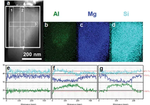
A detailed chemical composition analysis was performed in the elongated tail. Fig. 4a shows a close-up of the STEM
HAADF image of the tail at tilt angle of 0◦andFigs. 4a, 4b and 4c are the EDS mappings of Al, Mg and Si, respectively. Changes in composition are clearly seen which however could be related to changes in the foil thickness. In order to raise any doubt, line-scans were recorded in the long and transverse directions of the tail, which are numbered 1–3 inFig. 4a. The line scan 1 (Fig. 4e) shows a chemical composition which corresponds perfectly to the measurements #1 (red dashed line inFig. 4e–f) inTable 3. In contradistinction, the line scans 2 (Fig. 4f) and 3 (Fig. 4g) show that the Mg content decreases as the Al content increases while the silicon content is nearly constant. These results thus confirm that the changes in composition which appear inFigs. 4a–c are real and that Al and Mg can
substi-Fig. 4 – HAADF STEM image of the elongated part of the nucleus (a) and EDS mappings of Al (b), Mg (c) and Si (d) obtained from the white bold rectangle in a; EDS line-scans labelled 1 (e), 2 (f) and 3 (g) in (a) showing the change in content of the same three elements.
Table 4 – Chemical composition in selected areas of the round part of the nucleus of Fig. 5d (at. %).
Al Mg Si S Ti Fe 1 1.1 10.2 4.0 9.4 12.5 62.8 2 2.8 21.3 7.0 14.3 24.6 30.1 3 4.6 34.9 9.2 24.1 26.1 1.1 4 18.0 39.2 38.9 2.1 1.4 0.4 5 4.5 24.0 9.6 8.3 50.6 3.1
tute to each other. Accordingly, they suggest that the results in Table 3from this work and literature could possibly represent the same phase.
To study the chemical composition of the multi-phase rounded part of the nucleus, focused STEM EDS analyses were carried out with a sub-nanometric probe.Figs. 5b and 5d show a superposition of the Fe (red), S (blue) and Ti (green) maps and the related HAADF STEM images shown inFigs. 5-a and 5-c respectively. Quantitative EDS analysis was performed by integrating the signal over small boxes labelled 1–5 inFig. 5-d. The results are listed inTable 4.
These data are mainly indicative due to the overlapping of the different phases in each small box. Nitrogen has not been quantified inTable 4 due to the overlapping of Ti-La and N-Ka lines. Thus, inFig. 5d, the center of the nucleus is probably iron-base phase (box 1) while the shell around is cer-tainly a Mg-rich sulfide (boxes 2 and 3) which could possibly contain titanium. Further, the fan-like precipitate should be a titanium carbide or carbo-nitride (box 5) and the remain-ing area a (Al,Mg,Si) nitride (box 4). It should be noted that the iron phase in the center appears facetted (Fig. 5c) and that the fan-like precipitate seems to develop from the shell
around the iron center (Figs. 3a and 5a). Also noteworthy, Fe and S are detected between the rounded and elongated parts, and iron is also present at the outer border of the fan-like phase.
Finally, the foil and thus the different parts of the nucleus have been properly oriented for diffraction to have access to the crystallographic structure (seeFig. 6). Selected area elec-tron diffraction (b) and convergent beam diffraction (d, f, h) were performed as illustrated inFig. 6with the related BF TEM images shown in the top row. The greyed area ofFig. 3a in both the elongated and rounded parts of the nucleus have been indexed as trigonal AlMg2.5Si2.5N6with a = b = 5.44 Å and c = 4.82 Å (space group, P31m) according to Solberg and Onsoien [7](Figs. 6b and 6d). The fan-like precipitate can be indexed as cubic Ti(C,N)0.5with a = 4.2822 Å (space group Fm-3 m ICSD 618421 [12] (Fig. 6f) and the center of the nucleus as bcc-Fe (space group Im-3 m - ICSD 631734 [13](Fig. 6h). It was hardly possible to get information about the Mg-rich sulfide areas.
Though the most commonly reported nuclei are mixtures of oxides and sulfides, the literature shows that other types of phases may be encountered. In the present work, one sin-gle nucleus has been studied with modern analytical means which showed it, for the first time, to consist of at least four phases: 1) a center rich in Fe and indexed as bcc; 2) a sul-fide rich in Mg; 3) a titanium carbo-nitride; 4) a nitride rich in Al, Mg and Si. From the spatial distribution of the phases, it seems that the above sorting corresponds also to the forma-tion sequence of the nucleus: the Mg-rich sulfide is around the Fe-rich center; the Ti(C,N) fan-like precipitate develops from this sulfide; finally, the (Al,Mg,Si) nitride precipitates from all around this carbo-nitride. Moreover, it appears that the actual
Fig. 5 – HAADF STEM images of the rounded part (a) and of the center (c) of the nucleus, and superimposition of EDS mappings of Fe (red), S (blue) and Ti (green) of the corresponding zones (b and d).
Fig. 6 – BF TEM images of the different parts of the nucleus (a, c, e and g) and associated electron diffractions (b, d, f and h).
substrate for graphite nucleation has been here the (Al,Mg,Si) nitride. This is at change with respect to the previous works showing nitrides[3,4]in that the inter-relation between the phases is here clearly seen.
The present results are also the first to report a Fe-rich bcc center which is guessed to be a remaining of the FeSi addition for inoculation. Furthermore, the elongated form of the nucleus is a definitive proof that the shape of a nucleus
does not determine that of the emerging graphite precipi-tate.
4.
Conclusion
The use of modern analytical techniques combined with TEM allowed determining the phases that compose the nucleus of a graphite spheroid selected in a thin-wall cast-iron casting. The sequence of formation of this nucleus can be as follows: 1) a facetted center rich in Fe indexed as bcc which may be inher-ited from the inoculation process; 2) a shell around this center made of a sulfide rich in Mg; 3) then a fan-like titanium carbo-nitride developing from the shell; and finally 4) an carbo-nitride rich in Al, Mg and Si which precipitated both around the aggregate of the other phases and as a tail attached to this aggregate.
Conflicts of interest
The authors declare no conflicts of interest.
Data availability
The raw/processed data required to reproduce these findings cannot be shared at this time as the data also forms part of an ongoing study.
Appendix A. Supplementary data
Supplementary material related to this article can be found, in the online version, at doi:https://doi.org/10.1016/j. jmrt.2020.02.093.
r e f e r e n c e s
[1] Skaland T, Grong O, Grong T. A model for the graphite formation in ductile cast iron: part I. Inoculation
mechanisms. Metall Trans A 1993;24A:2321–45, http://dx.doi.org/10.1007/BF02648605.
[2]Pan EN, Ogi K, Loper CR. Analysis of the solidification of compacted/vermicular graphite cast iron, 90. Chicago; USA: In: Transactions AFS Society, Proceedings of the 86th Annual Meeting; 1982. p. 509–27.
[3] Igarashi Y, Okada S. Observation and analysis of the nucleus of the spheroidal graphite in magnesium-treated ductile iron. IJCMR 1998;11:83–8,
http://dx.doi.org/10.1080/13640461.1998.11819261. [4] Nakae H, Igarashi Y. Influence of sulfur on heterogeneous
nucleus of spheroidal graphite. Mater Trans 2002;43:2826–31, http://dx.doi.org/10.2320/matertrans.43.2826.
[5]Jiyang Z. Colour metallography of cast iron. Part 3, China Foundry 2010;7:77–88.
[6]Harding RA, Campbell J, Saunders NJ. An assessment of our current understanding of the inoculation of cast iron. Roosemont, IL: In AFS International Inoculation Conference Proceedings; 1998.
[7] Solberg JK, Onsoien MI. Nuclei for heterogeneous formation of graphite spheroids in ductile cast iron. Mater Sci Tech 2001;17:1238–42,
http://dx.doi.org/10.1179/026708301101509313.
[8] Onsoien MI, Grong O, Skaland T, Jorgensen K. Mechanisms of graphite formation in ductile cast iron containing rare earth metals. Mater Sci Tech 1999;15:253–9,
http://dx.doi.org/10.1179/026708399101505815.
[9] Laffont L, Jday R, Lacaze J. An electron microscopy study of graphite growth in nodular cast irons. Metall Mater Trans A 2018;49A:1287–94,
http://dx.doi.org/10.1007/s11661-018-4508-4.
[10] Stadelmann P, JEMS-SWISS version 4.8130U2019b17, web site: https://www.jems-swiss.ch/.
[11] Mercier JC, Paton R, Margerie JC, Mascré C. Inclusions dans les sphéroïdes de graphite. Fonderie 1969;277:191– 200.
[12] Alyamovskii SI, Mitrofanov BV, Zainulin Yu G, Shveikin GP. Coefficients of thermal expansion of titanium carbonitrides. High Temp 1973;11:616–61.
[13] Straumanis ME, Kim DC. Lattice constants, thermal expansion coefficients, densities and perfection of structure of pure iron and of iron loaded with hydrogen. Zeitschrift fur Metallkunde 1969;60:272–7.