OATAO is an open access repository that collects the work of Toulouse
researchers and makes it freely available over the web where possible
Any correspondence concerning this service should be sent
to the repository administrator:
[email protected]
This is an author’s version published in:
https://oatao.univ-toulouse.fr/24685
To cite this version:
Fayollas, Camille and Fabre, Jean-Charles and Palanque, Philippe
and Cronel, Martin and Navarre, David and Deleris, Yannick A
Three-fold Approach towards Increased Assurance Levels for
Interactive Systems: A Flight Control Unit Case Study. (2016) In:
International Conference on Human-Computer Interaction in
Aeronautics (HCI'Aero 2016), 14 September 2016 - 16 September
2016 (Paris, France).
A Three-fold Approach towards
Increased Assurance Levels for Interactive Systems:
A Flight Control Unit Case Study
C. Fayollas
2,3, J.-C. Fabre
3, P. Palanque
2, M. Cronel
2, D. Navarre
2, Y. Deleris
11 AIRBUS Operations, Toulouse, France
2 ICS-IRIT, Université de Toulouse, France
3 LAAS-CNRS, Université de Toulouse, France
(cronel, fayollas, navarre, palanque)@irit.fr, [email protected], [email protected]
ABSTRACTInteractive cockpits have been used since the early 00’s in many aircraft cockpits, but the use of interactivity still remains limited to non-critical functions even in the most recent aircrafts. Indeed, engineering such interactive systems is still a challenge and their engineering has not reach the Design Assurance Level required for critical functions. In interactive cockpits, interaction takes place through graphical input devices and keyboards (such as the Keyboard Cursor Control Unit in Airbus family) while the behavior of the User Interface (UI) must be compliant with the specifications defined in ARINC 661 standard. The tool-supported three-fold approach presented in this paper proposes means for increasing the assurance level of interactive systems. The approach includes a formal description technique for describing each component of an interactive system (detection and prevention of development faults), a command and monitoring technique dedicated to interactive systems components (detection of natural faults) and a segregation runtime environment (prevention of faults propagation) We report on the implementation of a Flight Control Unit (FCU) panel using this approach, inspired by the FCU of the A380.
Keywords
User Interfaces, Interactive cockpits; model-based development, dependability
INTRODUCTION
In classical cockpits (such as the glass-cockpit [14] introduced by Airbus in the early 80’s) input from pilots takes place through physical objects such as knobs, buttons, side stick, … while output is distributed on digital displays and dials each of them being managed by dedicated hardware. In this generation of cockpits, input and output are processed in an independent manner leaving the connection between them to the pilot (through cognitive processing usually supported by the collocation of input and output devices in the cockpit). Dependability of these cockpits is mainly addressed by formal description techniques (for fault prevention) and redundancy (for fault tolerance) which (during operation) enables pilots to enter
information via multiple input devices and receive information through multiple redundant displays.
With the introduction of the ARINC 661 specification [2] in the 00's, the new generation of aircraft (e.g., Airbus A380, A350 WXB, Boeing 787 …) features graphical user interfaces (GUI) in their cockpit. On the user side, these graphical interfaces offer integrated management of input and output through graphical devices, interactive widgets (radio buttons, text boxes …) very similar to the ones available in standard interactive systems (e.g., office and home computers). On the technical side, such interfaces require complex software components (such as windows managers) to connect input devices to interactive components on the graphical displays. This technical complexity calls for specific methods and tools for engineering such interactive systems and this is why GUIs in interactive cockpits are currently only used for non-safety-critical functions.
The use of graphical interfaces in the cockpit brings a lot of advantages such as increasing the upgradability of the cockpit, decreasing pilots’ workload or improving bandwidth between flying crew and the cockpit. For all of these reasons, aircraft manufacturers (such as Airbus) are studying the possibility of replacing hardware control panels by graphical interfaces, even for safety-critical functions. This raises the issue of the dependability increase of graphical interfaces and the challenge is now to reach the same level of dependability for them as the one of previous generation of cockpits. Even in the field of non-critical systems reliability of interactive application is clearly an issue, usually handled by manufacturers through repetitive patches and by users through regular reboots. To increase the development assurance level of interactive systems, we proposed a three-fold approach based on the use of formal description techniques to detect and remove development faults [8], software patterns for detecting natural faults [4] and segregation of hardware and software for avoiding faults propagation [1].
The paper is structured as follows: next section details the issues raised by engineering interactive systems and outline the solutions proposed in this paper. Section 3 introduces the case study that is used throughout the paper to demonstrate the applicability of the approach. It is a “guiding thread” to explain the proposed approach and to
Permission to make digital or hard copies of all or part of this work for personal or classroom use is granted without fee provided that copies are not made or distributed for profit or commercial advantage and that copies bear this notice and the full citation on the first page. To copy otherwise, or republish, to post on servers or to redistribute to lists, requires prior specific permission and/or a fee.
make it more concrete. The fourth section provides an overview of the various components of the approach dedicated to the development of reliable and fault-tolerant interactive systems. Section 5 describes the implementation of the approach that is compliant with ARINC 653 specification. The last section concludes the paper and highlights perspectives and future work.
PROBLEM SPACE AND OVERVIEW OF THE CONTRIBUTION
Failure Modes Taken Into Account
Concretely, improving development assurance level of interactive systems aims at avoiding four possible failures as required by the European Aviation Safety Agency CS-25 (Certification Specifications for large aeroplanes [6]):
Loss of control: loss of function so that control (from crew member to aircraft systems) is not performed. Erroneous control: malfunction so that control is
performed in an inappropriate manner (wrong control, control sent with a wrong data or unexpected control sent without crew member action).
Loss of data display: loss of function so that the data display (from aircraft system to display for crew member) is not performed.
Erroneous data display: malfunction so that the data display is performed in an inappropriate manner or unexpected change of data display without the aircraft system asking for it. In both cases, the wrong data display may be misleading to crew members.
Considered Fault Model
In this paper, we consider that the failures presented above can be caused by several type of faults. These type of faults constitute the fault model that encompasses software faults such as design faults during the system development and physical faults in particular transient single or multiple bit-flips caused by electromagnetic fields or radiation [18]. The evolution of modern IC components may lead in the next future to a higher probability of physical faults in operation. Although the recommendation for avionics systems is 100 FITs over 25 years lifetime, the current Deep Sub-Micron (DSP) technology may lead to a failure rate up to 1000 FITs, only during 5 years operational life time [19]. This is major worry in the avionics industry since this tendency has two bad sided effects, i) the reduction of the life time of the systems and ii) the increase of the failure rate due to hardware faults. In addition to this, the complexity of the
stack of software layers may lead to a large number of residual software faults impacting the software.
Overview of the Contribution
In this paper, we focus on the interactive system dependability as a computer-based systems; human errors during operation are out of scope of this work. Although human errors can be an important source of problems in avionics, human reliability aspects must be considered independent from the dependability of the cockpit platform. Furthermore, development software faults and natural faults in operation that we considered in this study are not influenced by operator’s behavior.
This paper presents a three-fold approach targeting at improving development assurance level of interactive systems. First, at development time the UI and all its underlying software components are described using a formal description technique dedicated to the formal modelling of interactive systems. This approach (see Fig. 2) has been improved over the years and already applied in the area of interactive cockpits [5] and targets at detecting faults made at development time by formal analysis of the models. Second, the approach embeds the COM/MON [23] design pattern for detecting natural faults occurring during operation (e.g., multiple bit flips [18]). Third, we propose a fault tolerant architecture based on the ARINC 653 standard, more precisely on an IMA (Integrated Modular Avionics) kernel providing time and space partitioning to avoid propagation of faults from one faulty component to another one.
Fig. 2. Complementary approaches to increase development assurance level of interactive systems
CASE STUDY: THE FCUS APPLICATION Interactive Cockpit Architecture
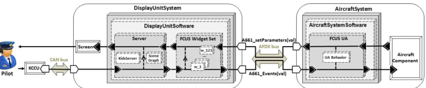
The interactive Control and Display System (CDS) of the Airbus A380 is composed of 8 outputs devices called DUs (Display Unit) and 2 input devices (called KCCUs (Keyboard and Cursor Control Unit) which gather in the same hardware component a keyboard and a trackball (see Fig. 1). A DU device is composed of a LCD screen, a graphics processing unit and a central processing unit
Segregation The approach in the paper Formal Methods COM/MON design pattern Fig. 1. Simplified architecture of an interactive cockpit (compliant with the ARINC 661 standard) implementing the FCUS application
running an ARINC 653 [1] operating system kernel. The DUs are connected together and with the KCCUs through four segregated and redundant CANs networks (Controller Area Network). The DUs are connected to the aircraft systems through the AFDX network (Avionics Full DupleX switched Ethernet). The UA (User Application) is the interactive part of the avionics functions belonging to the aircraft systems.
The interactive system architecture in the cockpit (depicted in Fig. 1) and the interactive applications are based on the ARINC 661 specification [2] which specifies, first the communication protocol between the CDS and the aircraft systems and second, the software interface of interactive objects (called widgets) which can be buttons, editboxes, checkbuttons, ... as in standard user interfaces.
Fig. 3. Snapshot of the FCUS application (left: EFIS CP ; right: AFS CP)
The Flight Control Unit Software Application
In the Airbus A380, the Flight Control Unit is a hardware panel (i.e. several electronic devices such as buttons, knobs, displays …) providing two services: one managing aircraft information called EFIS (Electronic Flight Information System) and the other one managing the autopilot called AFS (Auto Flight System). Several of the actions that can be achieved by the pilot through the use of the Flight Control Unit are critical. Therefore, the Flight Control Unit is a good candidate when considering the replacing of critical hardware panel by graphical interfaces.
We use as a case study an interactive software version of it, providing the same services. This application is called FCUS (for Flight Control Unit Software) and is composed, as shown in Fig. 3, of two interactive pages:
The Electronic Flight Information System Control Panel (EFIS CP) which allows configuring piloting and navigation displays.
The Auto Flight System Control Panel (AFS CP) which allows the setting of the autopilot states and parameters.
The FCUS application is composed of 123 widgets of 11 different types that are quite representative of the 77 widgets types defined by the ARINC 661 specification [2].
Interactive system Functioning
To understand the functioning of the FCUS application, we take the concrete scenario of a pilot engaging a new aircraft heading (the direction pointed by the aircraft) on the FCUS. In this case study, we will more particularly focus on the generic part of the interactive system; our main interest is thus to ensure that the CDS (server and widgets in Fig. 1) of the interactive system processes correctly input events from crew members, and send graphical commands to the LCD screen according to the data received from the UA. Sequence diagrams are really good candidates to identify all the functions and elements of a system; they helps in understanding the system functioning and enables the identification of the function which, in case of failure, may lead to one of the failure modes presented in previous section. They thus support both the system formal development and the application of the COM/MON approach.
The sequence diagram of the engagement of a new aircraft heading is presented in Fig. 4. When the autopilot is active and in mode Heading/Vertical-Speed, it is programmed to maintain the heading chosen during the creation of the flight plan. If the pilot needs to modify the value of the aircraft heading during the flight, he/she can use the FCU application as the following:
1) The pilot clicks on the heading_ebn EditBoxNumeric, the server processes the KCCU event and sends it to the concerned widget (the heading_ebn) that processes it by opening itself and sending a rendering update notification to the server.
2) The pilot types the desired value. The server forwards the event to the heading_ebn that updates its value and asks the server for a rendering update.
3) The pilot validates the value by pressing the validation key. The server forwards the event to the heading_ebn that processes it and asks the server for a rendering update.
4) At the end of this processing, the heading_ebn sends an A661_STRING_CONFIRMED(newValue) event to the UA. The UA processes this event by updating the temporary heading value, checking its consistency and sending a validation to the heading_ebn.
5) The pilot move the cursor to the engagement button, the server processes the events and updates the cursor rendering.
6) The pilot clicks on the heading_ppb
PicturePushButton to engage the new heading value, the server processes the KCCU event and sends it to the concerned widget that processes it and sends a rendering update notification to the server.
7) At the end of the process of the click, the heading_ppb sends an A661_EVT_SELECTION event to the UA. The UA processes it, engages the new heading value and notifies the pilot of this engagement by asking the
heading_ebn to change its text color, the heading_ebn processes this and sends a rendering update notification to the server.
A THREE-FOLD APPROACH TOWARDS INCREASE ASSURANCE LEVEL FOR INTERACTIVE SYSTEMS
This section details the proposed approach. Fig. 5 positions our contribution with respect to the abstract diagram presented in Fig. 2. The interactive system development is achieved through the use of the ICO formal description technique; the COM/MON design pattern is applied to the CDS and the segregation is achieved through the use of ARISSIM, an ARINC 653 simulator.
Fig. 5. Instanciation of the complementary approaches to increase development assurance level of interactive systems
A Formal Description Technique for Detection and Prevention of Development Faults
To prevent the occurrence of software development faults, we propose the use of a formal-description technique dedicated to the specification and verification of interactive systems: the ICO (Interactive Cooperative Objects) formalism [17]. This formalism uses high-level Petri nets [12] to describe the behavioral aspects of the interactive system and concepts borrowed from the object-oriented approach to describe the structural and static aspects of the interactive system. This formalism enables the handling of the specific aspects of interactive systems such as their event driven nature. Its main interest is to provide a way for the interactive system developer to create non-ambiguous and concise models compliant with the system specifications.
The ICO formalism is supported by a tool named PetShop providing means to develop ICO models and formally verify properties over them [21] and also providing a runtime support for models’ execution. As the models are directly interpreted at run-time by this tool, the verified properties will be still valid at execution time. An overview of this preventive approach is done in [11] and its application for interactive cockpits is described in [5].
A COM/MON Approach for Detection of Natural Faults
For the detection of natural faults affecting the system during operations, we propose an approach relying on the conventional COM/MON architecture developed for fly-by-wire functions [23] (also known as self-checking architecture). The COM/MON approach relies on a command (COM) channel and a monitoring (MON) channel. The command channel ensures the function allocated to the classical component and the monitoring channel ensures that the command channel operates correctly. This architectural fault tolerance design pattern thus enables the detection of inconsistencies due to natural faults and is also valid for certification authorities.
More particularly, we apply it to the software elements of the CDS (cf. server and widgets in Fig. 1) thus leading to a self-checking CDS. In that case, the COM is then the classical interactive component, realizing the interactive functions. The MON is responsible for the validation of the COM outputs and is able to send error notifications in case of inconsistency.
The challenge in the COM/MON approach is the definition and implementation of the monitoring component. We propose to define it as a property checker. The monitoring component is thus responsible for the verification of several
The approach in the paper
COM/MON CDS ICO formal description
technique ARINC 653
segregation
server
kccu screen headingebn headingppb
mouseClicked(dx,dy) processMouseClicked(dx,dy) updateCursorRendering findWidgetAt(x,y) processMouseClick(x,y) updateRendering updateRendering pilot clickMouse updateRendering updateRendering seq updateRendering updateRendering updateRendering updateRendering mouseMove(dx,dy) processMouseMove(dx,dy) updateCursorRendering moveMouse mouseClicked(dx,dy) processMouseClicked(dx,dy) updateCursorRendering findWidgetAt(x,y) processMouseClick(x,y) updateRendering updateRendering clickMouse updateRendering updateRendering pressValidationKey pressValidationKey processValidationKey pressNormalKey processNormalKey(code) pressNormalKey(code) processNormalKey(code) 1 2 3 5 6 7 processNormalKey(code) Widgets 4
assertions associated to the interactive objects organization and their semantics in operational context. These assertions are associated in operation to runtime monitors. The identification of the assertions based on i) a failure mode analysis (using a FMECA [7]), ii) formal definition of the assertions associated to items failure modes and iii) the definition of the associated assertion monitors. A full account of the process leading to the identification of the assertion and their monitors is given in [10].
To deal with crash faults but also to handle its fail-silent behavior and enable fault recovery, the self-checking CDS must be replicated, due to space constraints, we do not focus on these aspects in this paper and more information about it can be found in [11].
A Segregated Architecture for Prevention of Fault Propagation
The segregation and error confinement relies on isolating the MON component from the COM component in separated error confinement areas called partitions, thus preventing fault propagation between the two components. The COM, composed of the classical CDS is located in a first partition while the MON, composed of all the assertion monitors is located in another partition.
The implementation relies on a basic ARINC 653 [1] operating system. ARINC 653 (Avionics Application Standard Software Interface) is the specification of a real-time operating system providing Time and Space Partitioning (TSP) for safety-critical avionics systems. Multiple applications of different software criticality levels (Development Assurance Levels – DAL [8]) can run on the same hardware in the context of Integrated Modular Avionics (IMA). TSP means that each partition is allocated a time budget and has its own protected memory space. TSP provides error confinement between executable code running in two different partitions. The APEX (APplication EXecutive) defines the API on this runtime support. Within each Partition, multitasking is allowed. The APEX API provides services to manage partitions, processes and timing aspects, as well as partition/process communication and error handling. The APEX defines communication channels called blackboard and buffer inside a partition, and called sampling and queuing between partitions. They rely on two communication policies:
Sampling and Blackboard only keep track of the last message and a read operation does not erase the information.
Queuing and Buffering implement a conventional FIFO queue. All the messages produced by the sender are received by the receiver.
Fig. 7 depicts the architecture of the mapping of our COM/MON architecture within an ARINC 653 operating system: the interactive part of appli1 is running in partition P1 on DU1, its monitoring counterpart MON_appli1 is running in P1 on DU2. A backup implementation of the former, named appli 2, can be implemented in the same way (for the replication purposes explained in previous section), but its COM part is running on DU2 and its MON part running on DU1.
Fig. 7. Simplified overall physical architecture
The pilot interacts with a given application through the KCCU. All inputs are delivered to both COM and MON components running on 2 different displays using a reliable broadcast protocol. The inputs are processed by the COM whereas the MON keeps them for later verification. The action performed by the COM, i.e. corresponding to the behavior of a given widget, produces an output that is delivered to the UA. The UA also receives the results of the check from the MON, before processing the results of the COM, i.e. an A661WidgetEvent.
The major time frame cycle for the partitions running on a DU must be lower than 33 ms to ensure correct rendering on the display [22]. In practice, the drift between the two clocks has a bounded temporal impact, just one cycle to validate an A661WiggetEvent. An extensive study of this problem can be found in [16].
APPLICATION OF THE APPROACH ON THE FCUS CASE STUDY
Formal Description of the FCUS
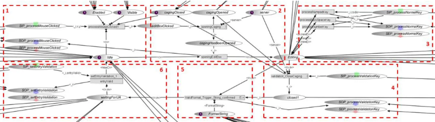
The FCUS application is developed using the ICO formal description technique presented in previous section. Therefore, all the software parts (white boxes in Fig. 1) of the CDS (server and widgets) are developed using the ICO formalism and following the specifications of the ARINC 661 standard [2]. The server is composed of two ICO models, one responsible for the hierarchy of widgets (called SceneGraph) and the other one responsible for all KCCU event management. Each widget is composed of an instance of an ICO model describing its behavior. Fig. 7 depicts an extract of an EditBoxNumeric (EBN) behavior:
1) The actual state of this EBN is: i) waiting for a user action (token in place Idle), ii) visible (token in place Visible) and iii) active (token in place Enabled). In this case, if the EBN receives a click (token in place SIP_processMouseClicked), it will process it (transition processMouseClicked1 producing a token in place editBoxClicked).
2) The EBN needs then to ask the server for a special mode called CagingMode (transition openingCaging) in which the user can only interact with this one widget, using the keyboard. When the server has activated this mode (token in place cagingOpened), the EBN switches to edition mode (token in place Editing).
3) The EBN is then able to process any keyboard input from user (token in place SIP_processNormalKey) in order to update the editing value.
4) When the user validates the editing value by pressing the
validation key (token in place
SIP_processValidationKey), the EBN asks the server for
closing the CagingMode (transition
validation_CloseCaging).
5) The EBN checks the format of the new value and sends (if correct) an A661_STRING_CONFIRMED event along with the new value.
6) The EBN is then waiting for the validation of this value by the UA (token in place waitingForUA). When the EBN receives the UA validation (token in place SIP_setEntryValidation), the EBN switches to the Idle mode with the new value.
Due to lack of space, we only depicted in Fig. 7 the normal behavior of the EditBoxNumeric. All the arcs that are not completely depicted in the Figure are responsible for all abnormal behaviors. Fig. 7 only shows 24 places, 9 transitions and 42 arcs while the whole EditBoxNumeric model contains about 65 places, 60 transitions and more than 200 arcs.
The complete modeling of the FCUS case study is composed of the modeling of the server (composed of two ICO models) and a total of 12 types of widgets. These widgets are representative of the 77 defined in the ARINC 661 standard and a total of 123 instances of them are running in the final application.
Application of the COM/MON Approach to the FCUS
As explained in previous section, the challenge while applying the COM/MON approach is the definition and implementation of the monitoring component. A presented previously, a safety analysis of the FCUS is the starting point of the development of the MON component. This is based on an analysis of the system functioning using sequence diagrams such as the one presented in Fig. 4. The analysis is done following the FMECA process [7] and is achieved through the completion of a FMECA table (see excerpt in Fig. 8). Each row of the FMECA table is leading to the definition of an assertion describing the correct behavior of the function studied.
To exemplify the FMECA table and the associated assertions and assertion monitors, we have selected one row of the FMECA table, typical of all the widgets ones. This raw is depicted in Fig. 8 and corresponds to the management of a KCCU event by a widget; here, it corresponds to the management of a mouse click by a PicturePushButton. We omit here the potential causes (fault model early defined) and the risk level (replaced by the consequence classification, corresponding to the failure mode classification presented earlier). Each row of the FMECA table corresponds to one function (item) of the widget and identifies the three failure modes of this function:
FM1: no execution. FM2: erroneous execution. FM3: unexpected execution.
1 2 34 5 6
Item Failures modes Local effects Upper-level effects Consequence
classification
ppb.processMouseClicked
Process the click, send the corresponding
A661_EVT_SELECTIONto the UA and send an update notification to the server
No execution
ppb.processMouseClicked.FM1
Upon the receipt of a kccu input event, the widget does not send any
A661_EVT_SELECTION
The pilot command is not sent to
the aicraft system Loss of control Erroneous execution
ppb.processMouseClicked.FM2 Upon the receipt of a kccu input event, the widget sends a wrong A661_Event(val) A wrong command is sent to the aircraft system Erroneous control Unexpected execution
ppb.processMouseClicked.FM3
The widget sends an
A661_EVT_SELECTION without receiving any kccu input event
A command is sent t the aircraft system without any user action
Erroneous control Fig. 8. Excerpt of the FMECA tables: process mouse click in a PicturePushButton
The assertion describing the correct behavior of the management of a mouse click by a PicturePushButton is depicted in Fig. 10.
Finally, each assertion is leading to two assertion monitors; the first one allowing to detect the failures modes FM1 and FM2 and the second one enabling to detect the failure mode FM3. The two assertion monitors for the management of a mouse click by a PicturePushButton are depicted in Fig. 9. For the FCUS case study, a complete FMECA has been done to identify the major risks and derived the
corresponding error detection and recovery mechanisms to ensure safety. The complete FMECA table (for the server and the widgets) enabled the identification of lead to the identification of potential failures that are not all critical, leading to the identification of around 30 critical assertions.
A Segregated Runtime Environment for the FCUS
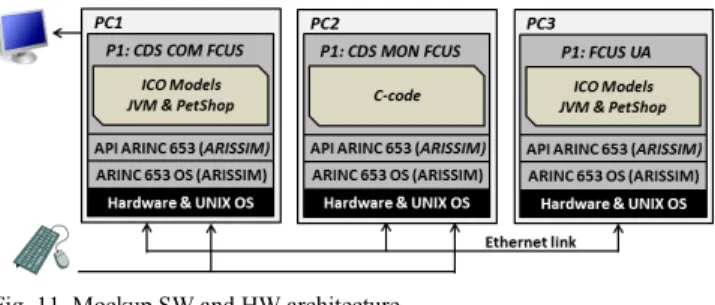
Our first mockup (see Fig. 11) has been developed on a network of 3 computers running UNIX and ARISSIM, an ARINC 653 simulator (see next subsection). PC1 runs a JVM and PetShop executing all the ICO models of the COM component in a partition, PC2 runs the C implementation of MON component in another partition. The UA part of the interactive system (running in PC3) is implemented in the same way than the COM component. However, since the server handling the widgets and the widgets are the focus in this paper, we do not detail the models for the UA that are used as test drivers for our mockup.
Fig. 11. Mockup SW and HW architecture.
A Runtime Support: ARISSIM, an ARINC 653 Simulator
Our ARINC 653 simulator has been developed on UNIX. It implements the TSP concepts and the mechanisms for partition communication. The functions provided to the partitions are not limited to the APEX API as the simulator is more a tool for proof of concepts than a real simulation environment. The UNIX system call interface is accessible, the development of applications can be done in C/C++, and we can launch a Java Virtual Machine in a partition. The setup of a simulation is described in two configuration files (one for communication channels/ports, on for partitioning temporal specification).
Space partitioning, i.e. memory management and protection, relies on UNIX and is implemented using a wrapper of the UNIX fork system call. The fork mechanism allocates a complete independent page table for each process newly created. A partition is a UNIX multi-threaded process.
The partition execution time is parameterized but fixed during the execution of the simulation. Time partitioning is implemented using UNIX signals (SIGSTOP and SIGCONT). These two signals are uncatchable and thus always lead respectively to a pause of the process (move process in waiting status) and to the continuation of the process (move process to ready status).
Inter-partition and intra-partition communication channels are implemented on UNIX sockets. The Queuing mode is based on a stream socket point-to-point communication to
A1.AM1: ppb.processMouseClicked.assert //MON state
boolean w.visible, w.enabled; // ppb.processMouseClicked.assert int errorDetected = -1;
if (functionCall == {source, w, processMouseClicked, parameters}){
if (w.visible == true && w.enabled == true){ boolean timeOut = startTimer(); } } while (!timeOut){ if (! timeOut && widgetEvent.contains({w,A661_EVT_SELECTION,∅}){ errorDetected = 0; sendError(functionCall, errorDetected); } }
if (timeOut && errorDetected == -1){ errorDetected = 1;
sendError(functionCall, errorDetected); }
A1.AM2: A661_EVT_SELECTION.assert //MON state
boolean w.visible, w.enabled; // ppb.processMouseClicked.assert int errorDetected = 0;
if (widgetEvent == {w,A661_EVT_SELECTION, ∅}){
if (functionCall.contains({source, w, processMouseClicked, parameters}) && w.visible == true && w.enabled == true){
errorDetected = 0; sendError(functionCall, errorDetected); }else{ errorDetected = 1; sendError(functionCall, errorDetected); } }
Fig. 9. Implementation of the assertion monitors in C for the assertion A1: process mouse click in a PicturePushButton
A1: Process mouse click in a PicturePushButton Let w be a PicturePushButton,
let f = {source, target, functionName, parameters} be a function call,
let We = {source, eventName, parameters} be a widget event f = {source, w, processMouseClicked, parameters} w.visible = true w.enabled = true
We = {w, A661_EVT_SELECTION, ∅}
Fig. 10. Formal definition of the assertion A1: process mouse click in a PicturePushButton
ensure that every message sent is received. Sampling mode is implemented in the same way but only keeps the last message sent, and the reading is non-destructive.
The simulator is open-source and available for use through a Web link with its documentation [3].
COM and MON Implementation
The COM component is composed of ICO models instances that are executed at runtime using PetShop, running on top of a Java Virtual Machine (JVM).
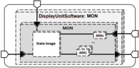
The MON component needs to be implemented in a diversified way from the COM component to deal with remaining software faults in the underlying runtime support (JVM and PetShop). The MON component is thus implemented in C for obvious efficiency reasons. As depicted in Fig. 12, it is composed of a state image (State Image), responsible to store and reconstruct within the MON component the state of the COM component (for instance, the widget tree), that is used as an oracle by each assertion monitors (AM1 … AMn). Each assertion monitor is implemented as a C function. The verification relies on the state image, some observable items coming from the COM through ARINC653 communication channels and all the KCCU events.
This implementation allows us to address both the issue of fault confinement (by means of the ARINC 653 architecture) and of diversity between COM and the MON while focusing on faults specific to interactive systems even though they remain at widget and server levels.
Fig. 12. Software architecture of the MON component
COM & MON Communication
Communication is achieved through the communication facilities provided by the ARINC 653 layer. Two communication channels are opened between the COM and the MON: a sampling channel and a queuing channel. Any information that is required for the verification of an assertion is transmitted through one these channels. The type of channel used depends on the data transmitted. The sampling channel is used when the last updated value of a given variable is required (for instance for the verification of data value); the queuing channel is used for the transmission of events (for instance all the widget events). Hooks are needed to capture the appropriate data for the verification; the hooks can be inserted in the implementation of the models or directly in the models runtime support. In both cases, observable items (event or data) are sent to the MON through an inter-partition
communication channel. In our experiment, hooks are implemented as a Java class, using the models runtime support to observe the changes in the ICO models.
CONCLUSION AND PERSPECTIVES
We have proposed a three-fold approach for the development of dependable interactive systems, based on the use of a formal description technique for their development together with a segregated fault tolerant software architecture. The proposed fault-tolerant approach is based on a COM/MON architecture that has already proven its efficiency for improving the dependability and certification of fly-by-wire functions [23]. The implementation targets interactive cockpits and is compliant with ARINC 661 and ARINC 653 specifications. We have implemented a mockup for this approach ensuring that moving from analog interactive systems to digital systems does not decreases the dependability level of such interactive systems. The current implementation is a proof of concept and should be followed by a real implementation in an industrial context to perform performance evaluation and optimizations.
Previous work has been done in each of the three elements of the approach (formal description techniques, fault-tolerant mechanisms and segregation) but they have not been integrated in a single framework.
The paper has demonstrated that the approach is applicable to a large scale study. So far, this is the only one that has been performed even though the formal description part has been extensively applied to multiple User Applications and even to the user interface server [5] for more than 10 years. The potential introduction of interaction techniques more sophisticated (than the WIMP ones proposed by the ARINC 661 standard) raises additional difficulties (e.g., dynamic instantiation of input devices) that have been presented (together with some solutions) in [13]. The approach is resource consuming, requires deep involvement of expert users but the availability of tools such as PetShop and ARISSIM provide extremely valuable support. This consumption of resources is acceptable in a safety critical context and is not higher than current approaches such as the ones currently used in the avionics domain (e.g., SCADE and SCADE Display).
On the perspectives side, it is important to note that whatever the implementation of the CDS is, analog or digital, with fault tolerance or not, perception, decision and actions from the flying crew are of primary importance. The user interface, the user interactions and the underlying software mechanisms keep the operator in the loop. This means that the flying crew is in charge of triggering commands (using KCCU and physical knobs) and assessing the current state of the aircraft (mainly based on perceived information on displays). In the field of safety critical systems the Human Factor has been most of the time perceived as the weak element of the Organization-Operator-Technological System triangle and as the main source of errors and failures. Indeed, as reported in [15]
79% of fatal accidents in aeronautics in 2006 have been attributed to human error. It is important to note however, that such perception has evolved over the last decade and that some authors represent the human as the last defense against organizational and technical failures [20]. Dealing with the human in assessing potential source of failures, requires looking at the human in a generic term as well as looking at the human in the specific case of the tasks and goals he/she has to achieve. This aspect has not been presented in this paper but is of the highest importance as dependability issues have to be addressed at global socio-technical system level. Indeed, the explicit representation of operators’ tasks makes it possible to identify training needs, workload and added complexity in presence of system or human error. However, dependability, usability and user experience are usually conflicting thus requiring careful management of the trade-offs when interactive critical systems are designed as demonstrated in [9] by the same research team in our joint-project with Airbus.
ACKNOWLEDGMENTS
This work was partly funded by Airbus under the contract R&T Display System X31WD1107313.
REFERENCES
1. ARINC 653. Avionics Application Software Standard Interface. ARINC Specification 653-2. AEEC, 2006 2. ARINC 661. Cockpit Display System Interfaces to User
Systems. ARINC Specification 661-5. AEEC, 2013 3. ARISS: http://makrin.github.io/ARISS/
4. Avizienis A. et al. Basic concepts and taxonomy of dependable and secure computing’, IEEE Trans. Dependable Secur. Comput., Vol. 1, No. 1, pp.11–33. 2004
5. Barboni E. et al. Model-Based Engineering of Widgets, User Applications and Servers Compliant with ARINC 661 Specification. Int. Conf. on Design Specification and Verification of Interactive Systems (DSV-IS 2006), pp. 25-38, Springer Verlag.
6. CS-25 – Amendment 14 - Certification Specifications and Acceptable Means of Compliance for Large Aeroplanes. EASA, 2013
7. Department of the Army, TM 5-698-4, Failure Modes, Effects and Criticallity Analysis (FMECA) For Command, Control, Communications, Computer, Intelligence, Surveillance, and Reconnaissance (C4ISR) Facilities, 2006.
8. DO-178C / ED-12C, Software Considerations in Airborne Systems and Equipment Certification, published by RTCA and EUROCAE, 2012.
9. Fayollas C. et al. An Approach for Assessing the Impact of Dependability on Usability: Application to Interactive Cockpits. EDCC 2014: 198-209
10. Fayollas C. et al. A Software-Implemented Fault-Tolerance Approach for Control and Display Systems in
Avionics. IEEE 20th Pacific Rim International
Symposium on Dependable Computing (PRDC2014). 11. Fayollas, C. et al. Interactive Cockpits as Critical
Applications: a Model-Based and a Fault-Tolerant Approach. In Int. Journal of Critical Computer-Based Systems, Inderscience Publishers, 2013
12. Genrich, H.J. Predicate/Transitions Nets. High-Levels Petri Nets: Theory and Application. pp. 3–43. Springer, Heidelberg, LNCS, Springer (1991)
13. Hamon-Keromen A. et al. Formal description of multi-touch interactions. EICS 2013: 207-216
14. Knight J. The Glass Cockpit. Computer, vol.40, no.10, pp.92,95, Oct. 2007
15. Krey N. (2007) The Nall Report 2007: Accident Trends and Factors for 2006. AOPA Air Safety Foundation. 16. Lauer M. et al. Worst Case Temporal Consistency in
Integrated Modular Avionics Systems. High-Assurance Systems Engineering (HASE), 2011 IEEE 13th Int. Symp. on, pp.212,219, 10-12 Nov. 2011
17. Navarre D. et al. ICOs: a Model-Based User Interface Description Technique dedicated to Interactive Systems Addressing Usability, Reliability and Scalability. Trans. on Computer-Human Interaction, ACM, Vol. 16(4), p. 1-56, 2009.
18. Normand E. Single-event effects in avionics. Nuclear Science, IEEE Transactions on, April, Vol. 43, No. 2, pp.461–474. 1996
19. Regis D. et al. IC components reliability concerns for
avionics end-users. Digital Avionics Systems
Conference IEEE/AIAA 32nd pp.2C2-1,2C2-9, 5-10
Oct. 2013
20. Sandom C. Success and failure: human as hero --human as hazard. In Proc. of Australian workshop on Safety critical systems and software and safety-related programmable systems, Vol. 86. Australian Comp. Society, Inc., Darlinghurst, Australia, 79-87.
21. Silva J. L. et al., Analysis of WIMP and Post WIMP Interactive Systems based on Formal Specification. In Int. Workshop on Formal Methods for Interactive Systems (FMIS 2013), Elsevier, 2013.
22. Card S. K. The Keystroke-Level Model for User Performance Time with Interactive Systems. Commun. ACM 23(7): 396-410 (1980)
23. Traverse P., Lacaze I., and Souyris J. Airbus fly-by-wire: a total approach to dependability. Proc. IFIP World Computer Congress, pp.191–212. 2004