HAL Id: pastel-00002096
https://pastel.archives-ouvertes.fr/pastel-00002096
Submitted on 5 Jun 2007
HAL is a multi-disciplinary open access archive for the deposit and dissemination of sci-entific research documents, whether they are pub-lished or not. The documents may come from teaching and research institutions in France or abroad, or from public or private research centers.
L’archive ouverte pluridisciplinaire HAL, est destinée au dépôt et à la diffusion de documents scientifiques de niveau recherche, publiés ou non, émanant des établissements d’enseignement et de recherche français ou étrangers, des laboratoires publics ou privés.
Alkali-Silica Reaction in Concrete Structures
Isabelle Comby Peyrot
To cite this version:
Isabelle Comby Peyrot. Development and Validation of a 3D Computational Tool to describe Damage and Fracture due to Alkali-Silica Reaction in Concrete Structures. Engineering Sciences [physics]. École Nationale Supérieure des Mines de Paris, 2006. English. �pastel-00002096�
Ecole Doctorale 364 : Sciences Fondamentales et Appliquées
N° attribué par la bibliothèque
|__|__|__|__|__|__|__|__|__|_
_|
T H E S E
pour obtenir le grade de
Docteur de l’Ecole des Mines de Paris
Spécialité «Mécanique Numérique»
Présentée par
Mme. Isabelle COMBY PEYROT
DEVELOPMENT AND VALIDATION OF A 3D
COMPUTATIONAL TOOL TO DESCRIBE
DAMAGE AND FRACTURE DUE TO ALKALI
SILICA REACTION IN CONCRETE
STRUCTURES
Directeurs de thèse : François BAY, Fabrice BERNARD, Pierre-Olivier BOUCHARD, Eric GARCIA-DIAZ
Soutenue publiquement le 01 Décembre 2006 devant le jury composé de :
M. Christian LA BORDERIE………...Rapporteur
M. Erik SCHLANGEN……….Rapporteur
Mme. Angélique VICHOT………Examinatrice
M. Jacky MAZARS………..Examinateur
M. François BAY ………Directeur de thèse
M. Fabrice BERNARD………...Directeur de thèse
M. Pierre-Olivier BOUCHARD…………...Directeur de thèse
REMERCIEMENTS
Cette thèse s’est effectuée en collaboration entre le Centre de Mise en Forme des Matériaux (CEMEF) de l’École Nationale Supérieure des Mines de Paris et le Département Génie Civil et Environnemental (GCE) de l’Ecole des Mines de Douai. Je remercie Monsieur Jean-Loup Chenot, Directeur du CEMEF et Monsieur Denis Damidot, Chef du Département GCE, de m’avoir donné l’occasion de réaliser ce travail.
Je tiens également à remercier Madame Angélique Vichot, Directrice de la Recherche de l’Association Technique de l’Industrie des Liants Hydrauliques (ATILH) et ses partenaires industriels pour s’être investis dans ce projet.
Mes premiers remerciements vont à Monsieur Jacky Mazars qui m’a fait l’honneur d’accepter d'être Président de mon jury de thèse. Je le remercie vivement pour l’intérêt qu’il a porté à mon travail. Mes remerciements les plus vifs s’adressent à Monsieur Christian La Borderie et Monsieur Erik Schlangen qui ont accepté d’être rapporteurs de ma thèse ainsi qu’à Madame Angélique Vichot pour sa participation au jury.
Je tiens à exprimer ma profonde reconnaissance à mes Directeurs de thèse avec qui j’ai eu la chance de travailler depuis le DEA: Eric Garcia-Diaz, Fabrice Bernard, Pierre-Olivier Bouchard et François Bay. J’ai apprécié tout au long de ces trois années les échanges scientifiques passionnants dans une ambiance amicale jusqu’à tendre parfois vers un processus incroyable où François arrivait à exprimer ce qu’Eric percevait! Je vous remercie tous pour votre enthousiasme, votre disponibilité et l’énergie que vous avez placée dans ce projet. Merci Pierre-Olivier pour la confiance que tu m’as accordée en me « léguant » le cours sur la Rupture durant deux années. Et un grand Merci à François pour ton aide précieuse pendant cette thèse mais aussi pour l’après-thèse. Je remercie également tous les chercheurs du groupe M3P pour leur disponibilité et leur bonne humeur ainsi que tous les chercheurs du Département GCE-Douai à qui je dois notamment la découverte des spécialités culinaires (certains se souviennent encore de la tarte au Maroual). Mille mercis à Tous.
Je souhaiterais également remercier toutes les personnes qui ont m’ont aidé au cours de ce travail. Je remercie Marie-Francoise Guenegan, Sylvie Massol, Geneviève Anseeuw, Christiane Collart et Carole Delchambre pour leur disponibilité, Francis Fournier, Emmanuel Levrat pour le support informatique, Brigitte Hanot et Sylvie Michel pour leur aide dans ma recherche bibliographique, Christophe Cappalaere, Mickael D’Helft, Guillaume Potier pour leur aide pendant la campagne expérimentale et de nombreux autres !
Je voudrais remercier mes collègues de travail que j’ai eu le plaisir de côtoyer durant ces trois années au CEMEF et au Département GCE et qui ont rendu très agréables ces trois années de travail. Je pense à Stéphane, Audrey, Aliza, Ludovic, Sébastien, Claire avec qui j’ai eu la chance de partager le bureau, mais aussi Antoine, Carole, Olivier, Elise, Mehdi, Christophe et Fréderic. Je souhaite enfin bonne chance à Raphaëlle pour les trois prochaines années.
Merci à mes amis toujours présents. Je pense aux ziziteviens (Juliette, Jocelyn, Fab, Yasmine, Manuella, Jean-Luc, Ludo from Sollies, JP), à Isa, Sylvain, à Véro, Nico, Marianne, Ben, Anne-Laure, Thom, Tony et pardon à ceux que j’oublie! Toutes mes pensées vont également vers mon amie très chère Charlotte qui me manque beaucoup. Merci a tous pour votre soutien sans faille!
pour tous leurs encouragements et leurs générosités mais je tiens à remercier ma Grand-Mère, Marie-Ange, Abel, Martine pour leur soutien permanent et leur présence le jour de la soutenance de thèse. Je remercie aussi mes deux frères que j’adore, Guillaume et Patrick. Je voudrais aussi bien sur remercier ma Mère sans qui je ne serais pas ici et je n’aurais jamais pu réaliser mes études, ses encouragements et son soutien permanent durant toutes ces années. Merci enfin à mon mari, Matthieu, qui m’a constamment encouragé et aidé, porté et parfois même supporté :). Merci pour ton soutien et tout ton Amour ! Cette thèse vous est dédiée.
Abstract
Development and Validation of a 3D Computational Tool to
describe Damage and Fracture due to Alkali-Silica Reaction in
Concrete Structures
Isabelle Combya,b
a
Centre de Mise en Forme des Matériaux, Ecole des Mines de Paris ; UMR 7635 CNRS, BP 207, 06904 Sophia-Antipolis Cedex, France
b
Ecole des Mines de Douai, 941, avenue Charles Bourseul, BP 938, 59508 Douai Cedex, France
The Alkali-Silica Reaction (ASR) induces aggregates swelling leading to irreversible degradation of concrete structures. Modelling damage and cracks in a 3D concrete structure submitted to ASR is hence of prime importance in civil engineering. FEMCAM (Finite Element Model for Concrete Analysis Method) software has been developed within this framework to model 3D numerical concrete. In this thesis, we have developed a mesoscale approach where concrete is considered as a heterogeneous material with two main phases: the mortar paste and aggregates. An elastic damage law has been successfully implemented to take into account the mortar paste behavior. The non local Mazars model with an implicit formulation is hence used to deal with damage. This model requires determining elastic and damage parameters. In this way, an experimental campaign has been carried out at the Civil Engineering Department of the Ecole des Mines de Douai to identify concrete material parameters. These experimental results have been compared with numerical ones through the inverse analysis modulus RheOConcrete. Applications on concrete (compression tests, three point bending tests and “Brazilian” splitting tests) have been also performed. The influence of the distribution, diameters and volume of aggregates on concrete behavior has been studied. The comparison between the numerical global responses of a concrete sample submitted to ASR and experimental ones are available. These comparisons are based on previous experimental works carried out at the Ecole des Mines de Douai. It leads to compare numerical and experimental approaches and to better understand the mechanism of ASR under the control of some parameters.
Finally, we have underlined the importance of describing macrocracks in concrete sample with a great accuracy to improve the model. The last part of this project concerns the implementation and the validation of a 3D Discrete Crack Propagation technique to model explicitly 3D crack propagation.
Keywords: Numerical modelling, Concrete, Alkali-Silica Reaction, Damage mechanics, Fracture
Résumé
Développement et Validation d’un Outil Numérique
Tridimensionnel pour décrire l’Endommagement et la Fissuration
causés par la Réaction Alcali-Silice dans les Structures en Béton
Isabelle Combya,b
a
Centre de Mise en Forme des Matériaux, Ecole des Mines de Paris ; UMR 7635 CNRS, BP 207, 06904 Sophia-Antipolis Cedex, France
b
Ecole des Mines de Douai, 941, avenue Charles Bourseul, BP 938, 59508 Douai Cedex, France
La Réaction Alcali-Silice (RAS) est une réaction chimique de dégradation des bétons occasionnant des désordres irréversibles au niveau de l’ouvrage. La modélisation de l’endommagement et de la fissuration d’une structure en béton tridimensionnelle victime de la RAS est donc de première importance en génie civil. Le logiciel FEMCAM (Finite Element Model for Concrete Analysis Method) a été développé dans ce cadre, afin de modéliser le comportement mécanique tridimensionnel des matériaux quasi-fragiles tels que les bétons. Dans cette thèse, nous avons développé une approche mésoscopique où le béton est considéré comme un matériau biphasé en présence de granulats et d’une pâte de mortier. Le modèle non local de Mazars avec formulation implicite a ainsi été implémenté et validé dans notre code Eléments Finis pour rendre compte du comportement élastique endommageable de la pâte de mortier. Nous abordons ensuite l’identification des paramètres élastiques et d’endommagement de ce modèle. Une attention particulière est portée à la campagne expérimentale menée au département Génie Civil de l’Ecole des Mines de Douai. Ces résultats expérimentaux ont été comparés aux résultats numériques via le module d’analyse inverse «RheOConcrete ». Des tests de compression, flexion trois points, essais brésiliens ont été ainsi réalisés. Les exemples d’applications proposés montrent l’influence du volume, de la répartition et du diamètre des granulats sur le comportement du béton. Nous utilisons ces résultats pour analyser les conséquences mécaniques de la RAS sur une éprouvette en béton. Les résultats numériques d’un béton soumis à un gonflement granulaire sont comparés aux résultats expérimentaux obtenus à l’Ecole des Mines de Douai. Cela permet de vérifier non seulement la cohérence du modèle numérique mais aussi de mieux comprendre l’influence de certains paramètres sur le mécanisme de la RAS. Enfin, nous soulignons l’importance de décrire avec précision les macrofissures générées par la réaction chimique. La dernière partie du mémoire concerne l’implémentation et la validation de la fissuration discrète en trois dimensions.
Mots-clefs: Modélisation numérique, Béton, Réaction Alcali-Silice, Mécanique de l’Endommagement,
Mécanique de la Rupture, Approche de fissuration discrète en 3D, matériau composite, méthode d’analyse inverse.
CONTENTS
CHAPTER
1
:
G
ENERALI
NTRODUCTION1.1 CONTEXT 1-1
1.2 STUDY DEVELOPMENT 1-2
1.3 PHD MANUSCRIPT OUTLINE 1-6
CHAPTER
2
:
A
REVIEW OF MODELS FOR CONCRETE2.1 INTRODUCTION 2-8
2.2 EXPERIMENTAL BEHAVIOR 2-8
2.3 A STATE OF THE ART REVIEW ON MODELS DESCRIBING THE MECHANICAL
BEHAVIOR OF CEMENT-BASED MATERIALS (MORTAR OR CONCRETE) 2-12
2.4 STATE OF THE ART REVIEW ON HETEROGENEOUS MATERIALS 2-25
2.5 CONCLUSIONS 2-30
CHAPTER
3
:
I
MPLEMENTATION AND VALIDATION OF A THREE DIMENSIONAL HETEROGENEOUS ELASTIC DAMAGE PROBLEM FOR CONCRETE3.1 THE FEMCAMSOFTWARE 3-33
3.2 MODELLING OF CONCRETE 3-34
3.3 THE ELASTIC DAMAGE MODEL USING A MIXED-VELOCIY PRESSURE
FORMULATION 3-39
3.4 SELECTION OF THE MODEL AND NUMERICAL STRATEGY 3-48
3.5 CONCLUSIONS 3-62
CHAPTER
4
:
I
DENTIFICATION OF CONCRETE BEHAVIOR:
THE INVERSE ANALYSIS MODULUS AND THE EXPERIMENTAL CAMPAIGN4.1 INTRODUCTION 4-64
4.2 INVERSE ANALYSIS MODULUS 4-65
4.3 PARAMETERS IDENTIFICATION 4-68
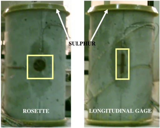
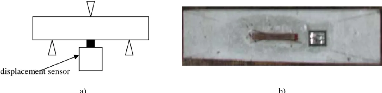
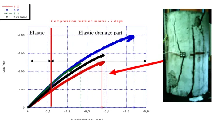
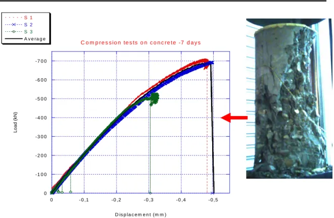
4.4 EXPERIMENTAL CAMPAIGN 4-72
4.5 SENSITIVITY ANALYSIS 4-84
4.6 CONCLUSIONS 4-92
CHAPTER
5:
IDENTIFICATION OF CONCRETE BEHAVIOR:
RESULTS AND SENSITIVITY ANALYSIS ON AGGREGATES PARAMETERS5.1 INTRODUCTION 5-94
5.2 STARTING HYPOTHESES 5-94
5.3 CONCRETE PARAMETERS:FIRST TECHNIQUE 5-94
5.4 CONCRETE PARAMETERS: SECOND TECHNIQUE 5-107
5.7 CONCLUSIONS 5-131
CHAPTER
6
:
M
ODELLING OF THE MECHANICAL EFECTS OF THE ASR6.1 INTRODUCTION 6-133
6.2 DESCRIPTION OF THE MODEL PROPOSED BY THE CIVIL ENGINEERING
DEPARTMENT OF THE ECOLE DES MINES DE DOUAI 6-134
6.3 THE SELECTED MODEL IN FEMCAM 6-137 6.4 MODELLING OF THE CONSEQUENCS OF THE ASR AFTER SEVEN DAYS 6-141
6.5 CONCLUSIONS 6-154
CHAPTER
7
:
I
MPROVEMENT OF THE DESCRIPTION OF THE ASR THROUGH THE DISCRETE CRACK APPROACH7.1 INTRODUCTION 7-157
7.2 STATE OF THE ART REVIEW ON 3D NUMERICAL APPROACHES OF FRACTURE 7-158
7.3 IMPLEMENTATION OF THE DISCRETE CRACK APPROACH IN THE FINITE ELEMENT
CODE FEMCAM 7-170
7.4 VALIDATION OF THE 3D CRACK MODEL 7-186
7.5 CONCLUSIONS 7-196
CHAPTER
8
:
G
ENERAL CONCLUSION AND PERSPECTIVES8.1 CONCLUSIONS 8-198
8.2 PERSPECTIVES 8-200
ANNEXES
A-1LIST OF SYMBOLS
(only the most frequently used)
c~ Characteristic parameter for the implicit formulation
D Scalar damage variable in isotropic damage model
da Crack length
max
d Maximum size of the aggregate
dmin Minimum size of the aggregate
dw Crack opening
E Young modulus for concrete
0
E Initial Young modulus of the compressive unixial stress-strain curve
C
E Young modulus of concrete
C A
E Young modulus for the aggregate
M
E Young modulus for mortar
C MP
E Young modulus for the mortar paste of concrete
e Deviatoric part of the strain tensor
F Reached load
f body forces per mass unit
f
G Fracture energy
C
G Critical Energy Release Rate
g aggregate volume in a volume unit of concrete
h Mesh size
IC
K Critical Stress Intensity Factor
I
K Stress Intensity Factor in mode I
II
K Stress Intensity Factor in mode II
III
K Stress Intensity Factor in mode III
L Tangent modulus
lc Characteristic length for the integral formulation F
m,μ Coefficients for the friction law
p Spherical part of the stress tensor
r Distance to the crack front
nr Normal to the section surface
t Time
v velocity field
R
V Real volume of aggregates generated with Femcam
T
V Theoretical volume of aggregates in a concrete sample
T
α , DT Scalar damage variable for tensile damage mechanism C
α , Dc Scalar damage variable for compressive damage mechanism α Mean compactness of the whole volume
t
Δ Time step
1
ε First principal strain
2
ε Second principal strain
3
ε Third principal strain
0
D
ε Initial damage threshold of damage growth
ASR
ε Strain due to the ASR
ASR ij
ε& Strain velocity induced by the chemical swelling in the aggregate
el ij
ε& Elastic strain velocity
Ti
ε Principal values of the strains due to positive stresses
Ci
ε Principal values of the strains due to negative stresses
crit
ε~ Initial crack threshold
Crit T
ε~ Initial crack threshold in tension
Crit C
ε~ Initial crack threshold in compression
χ Compressibility modulus
υ Poisson ratio
C MP
υ Poisson ratio for the mortar paste of concrete
C A
υ Poisson ratio for the aggregate
M
ν Poisson ratio for mortar
μ Shear modulus ρ volumic mass
σ Total stress tensor
δij =0 if i ≠ j c σ Compresssion strength t σ Tension strength 1
σ First principal stress
2
σ Second principal stress
3
σ Third principal stress
0
CHAPTER 1 : GENERAL INTRODUCTION
1.1 Context
he discovery of the Alkali-Aggregate Reaction (AAR) goes back to the 40’s in the United States in concrete pavements. In 1935 Holde observed the existence of chemical reactions between cements and certain aggregates in concrete. Stanton specified in 1940 the nature of the reagents at the origin of the disorders observed. This phenomenon was identified in France only since 1976. In 1993, Hornain classed the AAR in three major types:
T
- alkali-carbonate reactions; - alkali-silica reactions (ASR); - alkali-silicate reactions.
The most frequent reaction is the Alkali-Silica Reaction (ASR). This study will focus on this specific reaction.
The ASR product is a gel that increases in volume. The swelling forces generated may be sufficient to disrupt aggregate and the surrounding concrete, causing expansion, cracking, and associated deterioration. Typically, ASR results in the formation of map-pattern cracking of the concrete. It leads to the following consequences at a macroscopic scale:
- strain and displacement;
- network of cracks or cracks parallel to the armatures;
- Fragments breaking out of the surface (pop-out) [Bournazel 1997];
- A drop in the mechanical properties (mechanical strength and Young modulus); - The disappearance of lichens and mosses along cracks.
These reactions have the particularity to be localised and distributed randomly in concrete. Concrete deterioration caused by the ASR is generally slow, but progressive. Cracking generally becomes visible when concrete is five to ten years old. ASR has been implicated in the deterioration of various types of massive concrete structures, including dams, pavements, bridges, and other structures. The ASR is a major damage phenomenon for dams; this is due to the high humidity rate, the important mass of the structure and to the fact that dams do not usually contain steel reinforcement to restrain the expansion. Cracks facilitate the entry of de-icing salt solutions that may cause corrosion of the reinforcing steel, thereby accelerating deterioration and weakening of the structure.
Even though there are no documented cases of concrete structures failing due to ASR, it is a serious form of deterioration. Even since the problem was recognised, everything possible has been done to prevent it, adding mixtures for instance. So far over the last twenty or so years there have been no more major signs of the concrete “cancer” appearing in the newer buildings which have been produced, but there is always time.
a) b) Figure 1-1. a) Thomas E. Stanton next to a wall submitted to ASR - California, 1936; b) Chambon’s Dam (first
French dam where RAS has been discovered in France, 1976)
Preventive solutions (limitation of the alkali content of concrete, the use of supplementary cementing materials, the use of non reactive aggregates: but we have to be sure that the subject aggregates to be used are, in fact, nonreactive etc.) and curative solutions (waterproofing of concrete, injection of epoxides resins in cracks in order to limit the effects of the ASR etc.) exists. Moreover some recommendations have been made to avoid ASR as long as possible. But all these methods are inefficient and cost a lot. Only preventive action could lead to an eradication of this pathology.
1.2 Study development
The objective of the whole projects is:
- To understand the coupling relationship between the chemical reaction and the
mechanical consequences on the structures;
- To improve diagnosis tools by defining a methodology based on the quantitative
relationship between the chemical advancement of the reaction and the induced swelling.
Works have been already led by the Ecole des Mines de Douai (GC-Douai) on flint aggregates from almost ten years. The used methodology has clarified the coupling relationship between the chemical advancement and the macroscopic swelling. Now it is time to consider a numerical approach of this phenomenon. This modelling is developed within the framework of collaboration between the CEMEF (“Ecole des Mines de Paris”) and the GC-Douai of the Ecole des Mines de GC-Douai. This type of modelling induces a coupling between the chemical reaction and the swelling, knowledges on the mechanical degradation of the material, concept of cracks and multicracks. The aim of the numerical approach is to
understand the mechanism of the ASR under the controls of some parameters (hydration, number of aggregates, shapes of the aggregates, formulation etc.) which is difficult to analyse from the experimental side. In this way it is important to define in a first time the framework of this work.
1.2.1 Which scale can be used to describe the mechanical consequences
of the ASR with the best accuracy?
Figure 1-2 divides the three main scales in concrete. With the type of computer facilities available today it is impossible to describe the reaction from the micro to the macro scale. It is then necessary to do some hypotheses.
Macroscopic scale Mesoscopic scale Microscopic scale
Figure 1-2. From the mascrocopic scale (Millaud viaduct, France) to the microscopic scale.
At a macroscopic scale, the heterogeneous aspect of concrete is neglected. This level is useful in the framework of study of behavior concrete at a structural level.
At a microscopic scale local properties and type of cement (water-cement ratio, temperature, porosity, moisture content and hydration degree) are studied to understand the complex physical, chemical and mechanical behavior of the hardened cement paste.
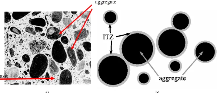
At a mesoscopic scale, three main phases appear [Bentz et al. 1995]: aggregate
Mortar paste
a) b)
Figure 1-3. a) The Concrete composition. Two main components are visible: the aggregates and the mortar paste [Mehta et al. 1993], b) Modelling of the Interfacial Transition Zone (ITZ)
1.2.1.1 The cement paste
The cement paste (mixture of cement and water) fill the existing vacuums between the grains. The paste plays the role of lubricant and adhesive.
1.2.1.2 Aggregates
The aggregates are natural materials of varying size and shape. Types of aggregates (geometry, physicochemical characteristics) are defined by standards. The term “coarse aggregates” refers to aggregate particles larger than 4.5 mm. The term “fine aggregate” takes into account aggregates with a diameter between 0.75 and 4.5 mm. Sand is commonly used for fine aggregate with a diameter lower than 0.75 mm.
The aggregates are not very deformable. They improve the tensile strength of the mortar paste by limiting microcracks of concrete.
1.2.1.3 The Interfacial Transition Zone (ITZ)
It has been discovered in 1956 by Farran [Farran 1956]. The Interfacial Transition Zone (ITZ) has mechanical properties very different from the mortar paste. The ITZ refers to the mortar paste located in the immediate vicinity of the coarse aggregate particles (as shown in figure 1-3.b). Its size ranges from 20 to 50 mμ depending on the mineralogical origin of the aggregate, the Water/Cement (W/C) ratio, the cement type etc.
It plays a fundamental role in the cracking process. Because the ITZ typically has a slightly higher W/C ratio than is observed in the entire mortar paste and because of the physical boundary between the different materials, the ITZ is weaker than the remainder of the mortar paste.
In this definition the contact between the aggregate and the mortar paste (possible decohesion, friction etc.) and the weaker zone around each aggregate are merged under the term of ITZ. The manuscript will distinguish clearly the contact and the weaker zone, which we will call ITZ, around the aggregate. Figure 1-3 describes the concrete composition at a mesoscopic scale.
****
The heterogeneous character of concrete is thus introduced. In the manuscript the mortar paste denotes the homogenization of the cement paste, with sand and fine aggregates, and the ITZ. We will consider the consequences in concrete at a mesoscopic scale as analysis appears to be the most practicable and useful approach for evaluating the composite behavior of concrete. Furthermore aggregates play a major role in the ASR:
- This chemical reaction is not localised and affect randomly aggregates in the structure; - It also induces micro and macro cracks in the sample. The aggregates location will
determine the crack path in the sample. It is thus important to describe as well as possible the aggregates locations and the mortar paste. It will also be important to quantify the number of reactive aggregates by representing them;
- It is also important to take into account the ITZ which is the privileged place of cracks
initiation.
1.2.2 Which size adopts to be representative of a massive structure?
In the classical approximations of heterogeneous materials the representative volume element (RVE) is usually considered to be infinitively large in comparison to the length scales of the microstructure. But the RVE size depends on the studied mechanical behavior. This size will be so much higher than the mechanical behavior will be complex. For concrete the RVE is about three times the size of the larger aggregates [La Borderie 2003]. The CSTB (Centre Scientifique et Technique du Bâtiment) has shown that computations converge when the size is ten times higher than the most larger aggregate, or when the volume is ten times higher than the volume of the largest aggregate [Mounajed 2002]. In fact it ensures that the tools of the continuum mechanics are available. In this way for an aggregate with a diameter of 20 mm, a study at a mesoscopic scale will be lead on sample with a 100 mm size. It corresponds in fact of the range size of samples used commonly for classical tests on concrete.
1.2.3 How link the results at a mesoscale with the micro and macro
scales?
A macroscale description of the heterogeneous concrete is limited by the power of computations. However on the future a good description of the material will be necessary to understand the effect of the ASR on concrete at a macro scale. The approach of the “equivalent homogeneous continuum” considers the heterogeneous volume has a homogeneous volume when the studied volume is rather than a physical scale. The objective of this method is to determine the global mechanical fields of the material using the knowledge of the local properties of the material components. In this way the main interest is
to compute a relation between the mesoscopic strains with the macroscopic mechanical behavior. A method for obtaining such a relation is referred to homogenisation or theory of
effective properties, by which the heterogeneous material is replaced by an equivalent
homogeneous continuum. The method is performed on a statistically representative sample of material, referred to as a representative volume element (RVE). Early approximations for the effective properties of heterogeneous materials were first developed by Voigt [Voigt 1889], Reuss [Reuss 1929] and Hill [Hill 1963]. In 1957, Eshelby [Eshelby 1957] obtained a relatively compact solution which has been a basis for many approximation methods. One of the most efficient numerical methods is the Finite Element Method, whereby the effective response can be obtained by volumetrically averaging numerical solutions of RVEs. From the micro to the mesoscopic scale a coupling with other software would be used. Some advanced softwares give us a state of the microstructure in durability problems. The software VCCTL (Virtual Cement and Concrete Testing Laboratory) [Bentz et al. 2002] is applied to predict a variety of physical properties of cement pastes. In our work these aspects will be not studied.
1.3 PhD manuscript outline
The manuscript is divided in eight chapters.
The starting point of this study is a review of models for concrete. We analyse the numerical methods which enables to model this behavior and we also analyse the different ways to represent the heterogeneous aspects of concrete.
The third chapter is devoted to the numerical implementation of the model in FEMCAM (Finite Element Model for Concrete Analysis Method) selected to simulate the degradation of concrete. We describe the model and the equations used in the software. The numerical model is then validated and justified.
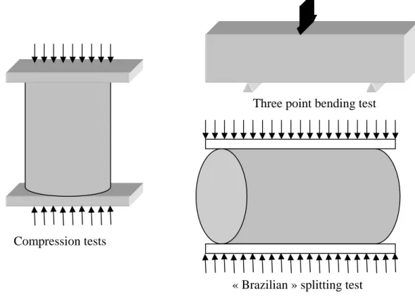
The fourth and fifth chapters underline the method we have used to identify the model parameters. We explain the experimental campaign we have carried out and the inverse analysis module “RheOConcrete” we have used to identify material parameters. Parameters are identified on compression and three point bending tests. We validate the parameters identification on the “Brazilian” splitting test. A sensitivity analysis concludes on the influence of the aggregates on the global response.
In chapter six, we focus on applications about the mechanical consequences of the ASR. We examine the numerical results and compared them to the experimental ones. Furthermore some tests will be made to understand the impact of the repartitions or the size of the aggregates on the swelling. This underlines also how we shall improve this numerical tool. The seventh chapter describes a way to improve the numerical tool by developing an efficient crack module in order to describe cracks in the sample with a great accuracy. We present the “Discrete crack approach” we have developed and validated.
CHAPTER 2 : A REVIEW OF MODELS FOR CONCRETE
2.1INTRODUCTION...2-8
2.2EXPERIMENTAL BEHAVIOR...2-8
2.2.1 Uniaxial compression test ...2-8 2.2.2 Uniaxial tension test...2-9 2.2.3 Multi-axial behavior...2-10 2.2.4 Crack closure effects ...2-11
2.3ASTATE OF THE ART REVIEW ON MODELS DESCRIBING THE MECHANICAL BEHAVIOR OF CEMENT-BASED MATERIALS (MORTAR OR CONCRETE)...2-12
2.3.1 Elastic plastic models...2-13 2.3.2 Damage models ...2-13
2.3.2.1 Elastic damage model...2-15 a) The equivalent strain in the Mazars model ...2-15 b) Damage threshold ...2-15 c) Damage decomposition ...2-16 2.3.2.2 Damage-plasticity coupling...2-17 2.3.3.3 Damage model with induced anisotropy ...2-18 2.3.3.4 Unilateral damage model ...2-18
2.3.3 Localization and mesh sensitivity...2-19
2.3.3.1 Non local damage mechanics ...2-19 2.3.3.2 Gradient formulations ...2-20 2.3.3.3 Internal length value...2-21 2.4STATE OF THE ART REVIEW ON HETEROGENEOUS MODELS...2-25
2.4.1 Statistical approach...2-25 2.4.3 Aggregates particles generation algorithms ...2-26 2.4.4 Real microstructure based on mesh generation...2-27
2.4.4.1 Projecting a specific mesh to the random aggregate structure ...2-27 2.4.4.2 Projection of a regular mesh on the random aggregate structure ...2-29 2.5CONCLUSIONS...2-30
2.1 Introduction
A bibliographic study on different experimental results is first presented to underline different possible modelling of mechanical behavior of concrete under various loadings.
The second part deals with the constitutive laws which aim at describing the behavior of quasi-brittle material as concrete or mortar*. Many theories describe the macroscopic behavior of these materials. We present a bibliographic study of these models describing the mechanical behavior of concrete. For the constitutive modelling, the focus here is mainly on continuum theories such as plasticity theory and continuum damage mechanics. We will underline how some of these models should be improved, thanks to the non local approaches. Advantages and drawbacks of constitutive models will be examined in this chapter to provide a general background and motivation for this study.
The different ways of modelling concrete are discussed in the fourth part. Two very different models appear: homogeneous models in order to simplify the numerical approach versus heterogeneous models. We will detail these different models.
We will conclude on the model we have chosen to describe the mechanical behavior of concrete. Special attention is given to starting hypotheses for this model.
2.2 Experimental behavior
Classical uniaxial tests (tension, compression) give us some important information on the mechanical behavior of concrete. Hence it is very useful to understand the role of the micro and macro cracks, friction, viscosity etc. We present here classical uniaxial and multiaxial tests for monotonic and cyclic loadings. Dynamic loadings will not be considered here since they do not have any impact on ASR.
2.2.1 Uniaxial compression test
Damage behavior is often studied for compressive stress states because of their importance at the industrial level. It is usually characterized using a uniaxial compression test on a cylindrical sample. The load-displacement curve obtained for such a test enables to identify the yield stress σc in compression. Figure 2-1 shows results obtained by Ramtani.
We can observe four stages in the material behavior. We first have a linear behavior of the material up to 50% of the σc value (stage 1). From 50% to 80% of the σc value, interfacial
cracks start to grow and the behavior stops being linear (stage 2). From 80% to 90% of σc,
interfacial cracks start to join, thus leading to macro-cracks initiation (stage 3). In the last stage, there is a fast degradation of mechanical characteristics which is related to the fast evolution of microcracks (stage 4).
*
Quasi-brittle means materials that show small plastic deformation after full fracture and relatively exhibit a relatively large cohesive process zone ahead of a pre-existing macrocrack where the interdependence between stresses and strains is nonlinear.
stage 4 stage 3 stage 2 stage 1 stage 0 2 ε σ ε C σ 1 ε
Figure 2-1. Stress-strain curve for a compression test.ε1 is the principal maximal strain. [Ramtani 1990, as
presented by Menou 2004]
2.2.2 Uniaxial tension test
Strength in tension is measured by tests such as Brazilian splitting test, three point bending test, and direct tensile tests.
The results in figure 2-2 clearly display two main stages, with a fracture zone much more localised than in compression. The behavior is linear almost up to the peak. Tests monitored by sound emission confirm that almost no degradation takes place before reaching the peak-value. In the post-peak stage, material degradation gets faster. Non-linearity and damage correspond to the initiation and growth of microscopic cracks which, when the peak load is reached, are located in a material band and end up being organized in macro-cracks. The stress drops quickly and becomes stable after a certain strain level. By the end of the test, the specimen stiffness is ten times smaller than the initial one.
Figure 2-2. Stress-strain curve for a direct tensile test. [Terrien 1980]
2.2.3 Multi-axial behavior
Under combinations of biaxial compressive stress, quasi-brittle materials exhibits strengths and stress-strain behavior which are different from that under uniaxial loading conditions. Concrete behavior under biaxial loading is characterized by an increase of the strength in comparison with the uniaxial behavior. We can quote the experimental tests of Kupfer [Kupfer et al. 1969]. Figure 2-3 shows the biaxial strength envelope of concrete under proportional loading.
Figure 2-3. Strength failure envelope under biaxial stress [Kupfer et al. 1969]. βp is the correspondent unconfined uniaxial compressive strength.
strength up to 16% of the uniaxial compressive strength, when the stress ratio σ1 /σ2 is 0.5. The applied boundary conditions, during the tests, have a great importance, on experimental results. These tests lead to the determination of envelopes areas in the principal stress space (σ1,σ2,σ3).
2.2.4 Crack closure effects
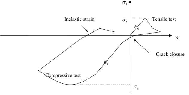
This phenomenon appears when the material is subjected to alternated loads. The uniaxial cyclic tensile tests underline the unilateral behavior of concrete. This phenomenon consists in a recovery of the stiffness between the tensile loading (damage and microcracks initiation) and a compression loading. The microcracks creation does not change material characteristics in compression. And it leads to a closure of microcracks and thus to a restoration of the material stiffness. Figure 2-4 underlines the unilateral behavior of concrete.
1 σ 1 ε t σ c σ 0 E 0 E Tensile test Compressive test Crack closure Inelastic strain
Figure 2-4. Unilateral behavior of a quasi-brittle material under uniaxial test. E0 is the initial material stiffness.
A specific test on concrete with metallic bars glued on the lateral surfaces of the sample to generate a distributed state of damage during the direct tensile test [Mazars et al. 1989] has underlined the unilateral characteristic of concrete.
The experimental behavior of concrete is rather complex. It is important to underline the different behaviors in compression and in tension. It is in fact a combination of phenomena such as linear elasticity, viscosity, microslidings (leading to permanent strains) and microcrackings (inducing a lower stiffness of the material). The relative importance of such phenomena depends on the type of solicitation. Modelling of concrete will have to take into account these aspects.
2.3 A State of the art review on models describing the mechanical
behavior of cement-based materials (mortar or concrete)
Quasi-brittle materials, such as concrete, belong to a heterogeneous material class whose non-linear behavior is rather complex. There is a very wide literature on experimental aspects of the mechanical behavior of these materials. The standard uniaxial tests provide information for modelling. Damage impacts the mechanical behavior of concrete in several ways:
- Modification of the elastic behavior which results in a change of the mechanical
characteristics;
- Modification of the plastic behavior (for concrete, these microstructural changes
correspond to decohesion in aggregate or in the mortar paste, or between them, slips along surface of decohesion).
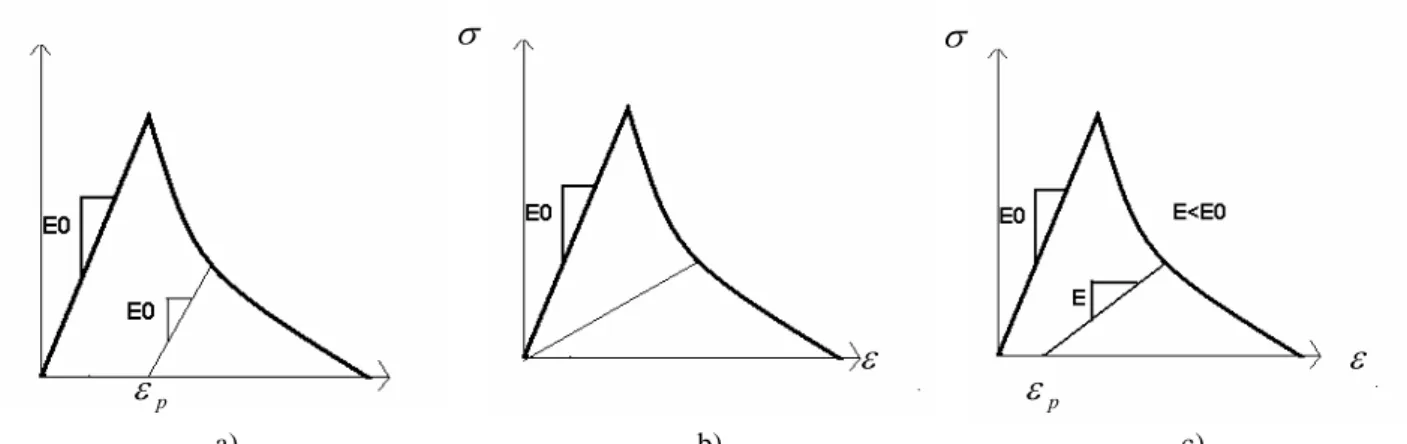
Many theories describe the macroscopic behavior of quasi-brittle materials. Various models of gradually increasing complexity have been proposed (see figure 2-5):
- Plastic models, in which the permanent unrecoverable strains appear after unloading; - Damage models divided into two main groups:
o Elastic-brittle, in which irreversible strains are negligible;
o Plastic-brittle, in which the permanent unrecoverable strains appear after unloading, in addition to the modification of elastic properties (modelled with damage model). σ σ σ p ε ε ε p ε a) b) c)
Figure 2-5. Typical stress-strain diagrams a) elastic-plastic material; b) elastic-damage material; c) elastic-plastic damage material.
Some models of these two main groups are going to be detailed and we will then focus on the Mazars model. Fracture in quasi-brittle materials such as mortar or concrete is a difficult issue because it induces localization and discontinuity in the displacement field. During the test, the stress-strain curve presents a negative slope: <0
ε σ
d d
(Hill criterion). Pijaudier-Cabot explains why this behavior leads to important numerical problems: the differential equations which govern equilibrium do not have any more the adapted mathematical form [Pijaudier-Cabot et al. 1997]. Therefore the stability criterion proposed by Hill is violated. Several models have been proposed. We will present in a second part models developed to avoid any mesh dependency.
Elastic plastic models provide a description of the development of plastic strain after the elastic stage. The first approach of the mechanical behavior of concrete supposes concrete as elastic perfectly plastic. We can quote several authors who have developed this approach. Lin and Scordelis [Lin et al. 1975] have largely developed this approach. The concrete is assumed to be elastic plastic in compression, but brittle in tension (see figure 2-6).
t σ ε σ C σ ε 0 E σ
a) Concrete in compression b) Concrete in tension
Figure 2-6. Assumed stress-strain diagram for concrete [Lin et al. 1975].
Reynouard [Reynouard 1974], Frantzeskakis [Frantzeskakis 1987] consider concrete as perfectly elastic in tension until fracture, and elastic plastic with hardening in compression.
Fracture criterion dependent on pressure, as the Rankine criterion can describe crack in tension. In compression several criteria can be used such as the Mohr-Coulomb (1911) or the Drucker-Prager (1952) criterion (see figure 2-7).
Figure 2-7. Representation of the Drucker-Prager and Mohr-Coulomb criteria in the stress deviator plane
(
σ1,σ2,σ3)
.Some of these models have been already implemented in FE code such as Adina (1982), Castem (1988) or Abaqus (1989).
2.3.2 Damage models
The concept of damage applied to quasi-brittle materials behavior was initially introduced by Kachanov in 1958 [Kachanov 1958] then developed by many other authors [Lemaître et al. 1992]. Damage mechanics is a theory describing the progressive reduction of the mechanical properties of material due to initiation, growth and coalescence of microscopic
material.
The distinction between a sound and a damaged material, at the base of this theory, has led to the concept of effective stress, defined by Kachanov. S denotes the section surface of one volume element, n being the outer normal, and the damaged surface (voids, cracks).
r
D
S
S~ denotes the effective resistant surface ( S~ < ) and takes into account the geometrical discontinuities and stress concentrations:
S D S S S~= − (2-1) nr Damage surface SD Total surface S
Figure 2-8. Uniaxial damage according to Kachanov.
The measure of the damage tensor , with respect to the normal n , is given by the following relationship: n D r S S S S S D D n ~ − = = (2-2)
If we consider that the defaults are uniformly distributed in each direction (isotropic damage), damage Dn does not depend on nr:
D
Dn = (2-3)
D is a scalar such as , with D = 0 (undamaged material) and D = 1 (completely damaged material). The damage variable D links damage and the mechanical behavior through the effective characteristic of the material. By definition:
1 0≤ D≤
D − = 1 0 σ σ (2-4)
E and σ are respectively the effective Young modulus and the effective stress. E0 and are
respectively the initial Young modulus and the initial stress. The effective stress concept introduced by Kachanov has been successfully applied to concrete by Mazars [Mazars 1984].
0
σ
2.3.2.1 Elastic damage model
The Mazars model (Mazars 1984) aims at modelling the modification of the elastic behavior; in this model, the damage variable is isotropic: it is modelled using the scalar variable D which affects stiffness.
a) The equivalent strain in the Mazars model
The concept of the equivalent strain introduced by Mazars takes into account the state and the intensity of local extension. The Mazars model thus considers only positive principal strains. This choice is well suited for quasi-brittle materials - and thus for mortar and concrete. The expression of the equivalent strain ε~ with respect to positive principal strains is given by:
∑
= + = 3 1 2 ~ i i ε ε (2-5) where 2 i i i ⎟⎟ ⎠ ⎞ ⎜⎜ ⎝ ⎛ + = + ε εε and
( )
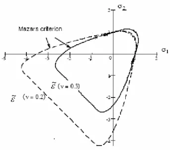
εi i∈[ ]1,3 denote the principal strain components. b) Damage thresholdAn evolutive threshold is introduced, depending on the damage variable D. Thus for a given damage state D, the form of the loading function is:
(
D)
Kf ε, =ε~− (2-6)
where K represents the variable related to the history of the damage. Damage D grows when the equivalent strain reaches a threshold K initialized at εD0.
(
)
(~ ) then 0 ~ , If ⎩ ⎨ ⎧ = = = − = ε ε ε K K D D K D f (2-7)ε~
ε~
Figure 2-9. Mazars model - Plot of the threshold area in the stress plane (σ1,σ2). [Mazars 1984]
c) Damage decomposition
It has been experimentally found that the response of concrete is different in tension and in compression. Damage D defined by Mazars is thus split into two parts:
C C T
TD D
D=αβ +αβ (2-8)
The parameter β is fitted from the response of the material to shear. It is usually considered as a constant. This coefficient is very sensitive. When β =1 , the shear strength is underestimated (here β =1.05). DT and are respectively the tensile and compressive parts
of the damage variable D.
C D
(
)
(
)
[
, 0]
, , 0 , ~ exp ~ 1 1 D C T C T C T D C T B A A D ε ε ε ε − − − − = (2-9) CA , AT, BC and BT are four material parameters. The weights αT and αC are defined such that:
(
)
∑
(
)
∑
= = + = + = 3 1 2 3 1 2 and ~ ~ i Ci Ti Ti i T i Ci Ti Ci i C H H ε ε ε ε α ε ε ε ε α (2-10)and the principal strains
( )
εi i∈[ ]1,3 check:Ci Ti i ε ε ε = + (2-11) 1 = i
H if εi ≥0, otherwise Hi =0. For pure tension cases, αC= 0 and D tends towards DT;
us note that if all principal strains are positive or null, αT =1,αC =0 and . Reversely, and T D D= 1 0 = = C T ,α
α D=DC. Figure 2-10 presents the results obtained by Mazars in 2D for a uniaxial tension test and a uniaxial compression test. These plots have been obtained with specific material parameters.
Figure 2-10. Mazars model in tension and in compression. [Mazars 1984]
The Mazars model is quite popular (easy to implement, robust etc.). However this model does not take into account the permanent strains and the unilateral effect. Most other damage models are an extension of this model (improvements for permanent strains, unilateral effect, anisotropic damage).
2.3.2.2 Damage-plasticity coupling
Damage models are motivated by the gradual initiation and propagation of microcracks and microvoids, and they describe the corresponding stiffness reduction. If the basic material between the defects remains elastic and the defects can close perfectly, the unloading branch of the stress-strain curve returns to the origin; real materials usually exhibit both permanent strain and a reduction of stiffness, and the unloading branches are somewhere between these two extremes. This induces the development of models that combine the frameworks of damage and plasticity. Bazant and Kim [Bazant et al. 1979] have proposed a damage-plasticity coupling (“Plastic-Fracturing”). It associates the damage theory with the fracture mechanism based on Dougill theory [Dougill 1976]. The La Borderie model adds a supplementary term to describe permanent strains. We assume here that only the elastic modulus is decreased by material damage according to the theory of continuum damage mechanics. The stress-strain relationship is the following:
p
ε
(
1 D)
E0(ε εp)σ = − − (2-12)
And the damage criterion includes permanent strains, by adopting the assumption of small strains:
(
)
= − = + =∑
( )
+ +∑
( )
+ i p i i e i p e K D f ε, ε~ , with ε~ ε~ ε~ ε 2 ε 2 (2-13)where + e i ε et + p i
ε are the principal parts of the elastic and plastic strain tensor. The La Borderie model has been implemented in the FE code Castem 2000.
2.3.3.3 Damage model with induced anisotropy
If an initially isotropic material is subjected to a general loading that leads to microcracks propagation, stiffness degradation is usually faster in specific directions. Consequently, the macroscopic properties of the material become anisotropic. Some theories take into account this property. To generalize the concept, the damage value becomes a fourth order tensor. The generalized relation gives [Ramtani 1990]:
0
) 1
( σ
σ = −Dn (2-14)
One of the major difficulties of this model is to keep the stress tensor symmetric.
2.3.3.4 Unilateral damage model
When damage D takes place under a cyclic loading, the previous formulation cannot capture the stiffness recovery observed during the stress reversal [La Borderie 1991]. This model distinguishes damage due to tension from damage due to compression. Since damage cannot decrease two independent scalars, damage DT and D are used. If loadings are C complex, damage may be a combination of and . We use a decomposition of the stress tensor into a positive part
T
D DC
+
σ~ and a negative part σ~ . The effective stress tensor can be − written: − + + = σ σ σ~ ~ ~ (2-15) In which σ~ is built with the positive eigenvalues and + σ~ with the negative ones, which − leads to
( )
σ~ =Tr σ~ + +Tr σ~ −Tr (2-16)
The La Borderie model enables to introduce unilateral effect according to the sign change and the anelastic strain part. The main difficulty of this model is that this formulation is very difficult to implement in a FE code. The reason is that the behavior law has to be inversed at each loading step. Furthermore it is not very well adapted to shearing effects.
Damage model for quasi-brittle materials can lead to a fast growth of damage after reaching the elastic limit in order to describe the softening behavior observed in experiments. As a consequence of this fast damage growth, local loss of ellipticity of partial differential equations governing equilibrium occurs immediately after reaching the damage threshold in quasi-brittle damage models (see example in 1D in appendix A.1). The loss of ellipticity of partial differential equations corresponds to a situation in which the number of linearly independent solutions to the equilibrium equations is infinite. This convergence of the finite element approximation to the actual, non physical solution of the problem is the origin of the apparent mesh sensitivity of damage models and other discontinuous descriptions of fracture.
We call “regularisation” methods the methods used to avoid the pathological localisation of deformation and damage growth by improving the continuum model. These techniques consist in introducing a "characteristic length" which enables to specify the localization zone width while preventing possible numerical problems which are dependent on it. The characteristic length can be introduced under various formulations:
- Nonlocal theories;
- gradient based formulation;
- Viscous or time-dependant terms in the constitutive model may prevent the loss of ellipticity of the original, time-independent behavior of solids [Needleman et al. 1988], [Sluys et al. 1994]);
- Cossera’s continua introduce micro-rotations as degrees of freedom, in addition to the conventional displacements. However this method does not lead to results in good agreement with experiment in the case of mode I loading [Mülhaus et al. 1987].
The non local and gradient approaches, which are closely related, are the most generally applicable techniques.
2.3.3.1 Non local damage mechanics
We denote ε the average of ε~ in a representative volume surrounding a point x. It is this variable which will control damage growth at point x:
( )
( )
∫
∫
= = V r V r ds x s x V ds x s s x V , ) ( , ) ( ~ ) ( 1 α α ε ε (2-17)V is the volume of the structure, ε~ is the equivalent strain at point s.α
( )
s,x is a homogeneous and isotropic weight standardized function which depends on the distance s− between the x points and s x . represents the material internal length. is proportional to the smallest size of the damaged zone [Pijaudier-Cabot et al. 1993].C
Figure 2-11. Weighted average for an irregular microstructure
Several functions have been considered in the literature to expressα . Among them, the Gaussian function is the most popular:
( )
⎟⎟ ⎠ ⎞ ⎜ ⎜ ⎝ ⎛ − − =exp 4 2 ² , c l x s x s α (2-18)The ε value - which can be considered as the non local equivalent strain - is the variable that controls the growth of damage in accordance with the following conditions:
K K
f(ε, )=ε − (2-19)
2.3.3.2 Gradient formulations
For sufficiently smooth ε -fields, the integral relation Eq. ( 2-17) can be rewritten in terms of gradient of ε~ by expanding ε~ into a Taylor series [Peerlings et al. 1996]:
.... ) )( )( )( ( ~ ! 4 1 ) )( )( ( ~ ! 3 1 ) ( ~ ! 2 1 ) ( ~ ) ( ~ ) ( ~ 4 3 + − − − − ∂ ∂ ∂ ∂ ∂ + − − − ∂ ∂ ∂ ∂ + − ∂ ∂ + − ∂ ∂ + = l l k k j j i i l k j i k k j j i i k j i i i i i i i x s x s x s x s x x x x x s x s x s x x x x s x x s x x s ε ε ε ε ε ε (2-20)
Neglecting terms of order four and higher in Eq. ( 2-20), definition of Eq. ( 2-16) of the non local equivalent strain can be replaced by:
ε ε
ε =~+~c∇~ (2-21)
In Eq. ( 2-21) the derivative of order second of the local equivalent strain introduce a spatial interaction in the numerical model (dependence of ε on the Laplacian of the local
Laplacien reduces the distance of interaction to an infinitesimal volume. The variation of
( )
yε~ , to a finite distance from x, has no effect on ε~
( )
x and ∇ε~( )
x and so on ε( )
x . This disadvantage can be avoided as follows:ε ε
ε − c~∇² = ~ (2-22) The non local strain is not given explicitly in terms of ε~ and its derivatives but as the solution of the boundary value problem:
⎪⎩ ⎪ ⎨ ⎧ = ∂ ∂ = ∇ − 0 ~ ² ~ n c r ε ε ε ε (2-23)
nr denotes the external normal unit vector. The boundary condition must therefore be
defined not only on the boundary of the problem domain but also on the internal boundary which surrounds the crack area. The physical interpretation of this type of boundary conditions remains an unresolved issue.
This is a local model in a mathematical sense, because the non local strain in a point depends only on the local strain and its gradient in the same point. Spatial interactions are therefore limited to the immediate neighbourhood in this model. This remark will influence the choice of the non local model in our code, more particularly for the modelling of problem with heterogeneous materials or with cracks. Compared to a classical model with an integral formulation, which directly modifies the equivalent strain (in the case of the Mazars model), this method can be used with any constitutive law. Indeed it is based on the computation of a non local strain tensor and used to evaluate any invariant (isotropy, anistotropy, plasticity etc.). The difficulty of this method is the evaluation of strain tensors instead of a scalar for the integral formulation.
2.3.3.3 Internal length value
Regarding the choice of the internal length value, it has a physical meaning: with the starting of the macroscopic fracture, the microscopic cracks coalesce, which is characteristic of a non-linear behavior, to form macrocracks or a Fracture Process Zone (FPZ) surrounded by a damaged material zone. A localization band is created when the strains cannot be described locally but have to take into account the interactions with the nearest points.
Figure 2-12. Section inside a FPZ; 1) « sound zone », 2) « damage zone »: some microcracks appear; 3) « Crack-damage zone »: the crack is visible on the surface but a part of the internal section is still active; 4)
classical continuous models. The non local approach enables to describe this FPZ. Its shape is controlled by the strain softening response of the material and by the internal length. Different methods exist: integral formulation, implicit gradient formulation etc. Each of them includes a non local parameter to identify. But the internal length is an additional parameter which is difficult to obtain directly by experiments.
A new theory of “fictitious crack” has been introduced by Hillerborg in 1976 and by Bazant [Bazant et al. 1983] with the “Crack Band Model” to idealise the behavior of a crack. The crack opening law is governed by three parameters: tensile strength, fracture energy , and the shape of the softening curve. The model is based on the assumption that is considered as a constant internal parameter of the material. It leads hence to consider that the smooth part of the stress strain curve in tension depends on the characteristic leng h l . In C this formulation the crack strain is related to the mesh size used. A first simple estimation was proposed by Rots for 2D configurations [Rots 198
f G f G t 8]: FE C r A l = (2-24)
Where is the area of the considered finite element and r is a parameter which is function of the finite element used. It is fixed to
FE
A
2 for linear finite elements. In the case of a 3D study:
3 V
lC = 2-25)
Where V is the volume of the finite element. It means that the non local parameter depends on the mesh size, the type of finite elements, and their position in the mesh. This approach is very easy to use but is insufficient for non regular meshes.
[Bazant 1989] have linked the internal length to the FPZ with a proportional relationship (see figure 2-13). If we consider that the area under the “a” curve is the same than the “b” curve, the following relationship can be established:
C
l
C
FPZ l
l =α× (2-26)
Incremental strain lc lFPZ b a Length coordinate x
Figure 2-13. Schematic profile of strain obtained analytically. [Pijaudier-Cabot et al. 1987, as presented by Haidar 2002]
Hence it is possible to measure the displacement field with a great accuracy in this zone and compare it to a numerical model [Geers et al. 1996]. The most accurate way of reaching the internal length is by a semi-inverse technique which is based on computations on size effect tests. The complete explanation of this effect is described in [Bazant et al. 1998]. This is due to the redistribution of the stored strain energy inside the structure where the size of each specimen can change but where the FPZ is constant. Hence scale effect tests can indirectly determine the parameter of the non local model. These tests are carried out on geometrically similar specimens on different sizes. But such identification requires many computations.
An approximation of the internal length l was obtained by Bazant and Pijaudier-C Cabot. Physically it is thus generally assumed that the lC value is between 3 dmax and 5 dmax
[Bazant et al. 1983], where dmax is the diameter of the larger aggregate. Relationships between
the internal length lC for the integral non local model and c~ for the gradient approaches have been discussed by many authors. Theorically, Peerlings considers the following relationship:
2 ~ lC2
c = (2-27)
Jason [Jason 2004] has carried out a numerical campaign where he has compared load-displacement curves on three points bending tests between the results obtained with an integral non local model and a gradient approach. He found:
16 9 ~ dmax2
Concrete exhibits a quasi-brittle behavior and the degradation process is linked to the macrocracks initiation and evolution in the sample. It induces a loss of stiffness, a strain localisation and irreversible strains. It is thus important to take into account this non-linear behavior.
Among the different numerical approaches, the elastic plastic and damage-elastic approaches are commonly used if we consider monotonic loading. We have chosen to use the classical Mazars model. This model is robust. It is also well adapted in the framework of this first 3D numerical description of the degradation of concrete submitted to the ASR as we consider a monotonic swelling of the sample.
We have also noticed the importance of introducing “regularization” methods to avoid localization of deformation. Two main approaches exist. The gradient approach seems to be more adapted for the description of heterogeneous material as concrete.
Experiments and numerical models reflect the complexity of the material. Whereas these numerical models try to model the global mechanical behavior of concrete as accurately as possible, they neglect the strong heterogeneity of concrete and consider it as a homogenised material. However figure 2-14 shows differences between the mechanical behaviors of the main concrete components. It underlines hence that aggregates induce a modification of the mechanical behavior of the mortar paste and that ductility has its origin in the bond between the aggregates and the mortar paste.
Principal strain ε Principal stress σ
Figure 2-14. Typical stress-strain curves for aggregates, mortar paste and concrete.
The properties of complex composite material are not equal to the sum of the components. Aggregates are generally linear elastic and the mortar paste has an elastic damage behavior. We will detail in the next part some of these models. However these approaches are:
- Unsuitable to characterise the entire fracture process from initiation to propagation and coalescence of macrocracks in concrete (fracture is often initiated at the ITZ and its evolution depends on the heterogeneity of the structure);
insufficient to understand the fracture process of concrete.
Hence different numerical models for the simulation of the fracture process in concrete at a mesoscopic scale have been proposed in recent years. Taking into account the heterogeneous aspect of concrete, they have the advantages to:
- estimate and understand local mechanisms of deformation;
- better simulate mechanisms of damage (damage is piloted by local values as the ITZ);
- become a precious tool for concrete formulations;
- describe accurately chemical degradation involving changes in mesostructures.
2.4 State of the art review on heterogeneous models
Few studies take into account the heterogeneous aspect of concrete, because of its complexity. We recall the three main phases which appear at a mesoscopic scale:
- The hydrated mortar paste; - The aggregates;
- The Interfacial Transition Zone (ITZ).
Numerical simulations of concrete are generally based on homogenization techniques in order to simplify the numerical approach. However only a few models exist (mainly for 2D configurations) because of computer storage, computation time, difficulties to represent 3D structures etc. We present them hereafter.
2.4.1 Statistical approach
A way to take into account the heterogeneous aspect of concrete is to distribute randomly the Young modulus and the strength on the mesh elements. The 2D Cesar LCPC probabilistic model is based on this concept. This randomly distribution leads to simulate the material heterogeneity and so a random cracking mode. This distribution follows a normal law, where the mean and the standard deviation are empiric functions of experimentally identified parameters. They depend on two parameters:
- The compressive strength σC; - The ratio
g T
V
V where V
T is the sample volume and Vg is the volume of the most
larger grain.
This model takes into account scale effects due to the heterogeneity of concrete [Rossi et al. 1992]. The aggregates shape plays an important role on the stress distribution and fracture energy of heterogeneous materials (they can be spherical or angular depending on their origin). However this model does not respect the aggregates geometry. Furthermore the ITZ is not taken into account. The contact is considered as perfect.
An interesting method consists in building the microstructure directly from an image (by the use of the scanning electron micrograph of a concrete specimen) of a real piece of material. Using image processing techniques the image can be splitted into three phases: mortar paste, aggregates and ITZ. But this method is very limited as it needs to ever have an
experimental concrete sample and the microtomographic techniques requires using samples with standard (usually very small) dimensions. First simulations were considering aggregates
as perfectly spherical. We can quote the model developed by Schlangen and Van Mier [Schlangen et al. 1992], Mounajed [Mounajed 2002] in the Symphonie code (CSTB). Figure 2-15 shows a few examples of modelling of aggregates in 2D and 3D. The 2D mechanical computation imposes a big hypothesis: we consider an identical aggregate repartition in the whole volume. This is hence the major drawback of the 2D aspect as we miss the random position of aggregates in the volume.
a) b) c)
Figure 2-15. Modelling of spherical aggregates in 2D-CSTB (a) or 3D (b) [Mounajed 2002]; c) Modelling of a granular skeleton in a cube of 24 mm size. [Lilliu 2002]
Other models ([Leite et al. 2003], [Häfner et al. 2006]) have been developed considering spherical or ellipsoidal aggregates (figure 2-16).
a) b)
Figure 2-16. a) Generated 3-D specimen with 60% aggregate content [Leite et al. 2003]; b) View on the section of a three-dimensional geometrical mesoscale model. [Häfner et al. 2006].
One of the drawbacks of this model is the spherical or ellipsoidal shape of the cells which is not compatible with reality. Wang [Wang et al. 1999] developed a procedure for generating a random structure for spherical and angular aggregates (figure 2-17).
![Figure 2-3. Strength failure envelope under biaxial stress [Kupfer et al. 1969]. β p is the correspondent unconfined uniaxial compressive strength](https://thumb-eu.123doks.com/thumbv2/123doknet/2992173.83550/21.892.276.610.698.1025/figure-strength-envelope-correspondent-unconfined-uniaxial-compressive-strength.webp)