REAL-TIME AURALIZATION OF INDUSTRIAL NOISE
JJ Embrechts Intelsig group, Dept Electrical Engineering and Computer Science, University of Liege, Belgium
L Bos Intelsig group, Dept Electrical Engineering and Computer Science, University of Liege, Belgium
1 INTRODUCTION
Auralization is defined as1 “the technique of creating audible sound files from numerical (simulated, measured, or synthesized) data”. In the field of room acoustics predictions, the simulated data consist in room impulse responses (RIR) or directional room impulse responses (DRIR) 2 which are mostly obtained by geometrical acoustics models.
A real-time and interactive auralization system has been developed within the research project Auralias3,4. Originally conceived for architectural acoustics applications, it is now intended to apply this system to auralize the effect of noise reduction solutions in industrial halls.
It is the purpose of this paper to report on these early experiments. The Auralias project is first presented, followed by the main characteristics of the real-time auralization system. Then, the specific characters of industrial noise problems are identified and their impact on the performance of the auralization system is discussed. Finally, the system is applied on a particular industrial noise problem and some results are commented.
2
THE AURALIAS RESEARCH PROJECT
This project is a collaboration between three research teams:
- the Intelsig group (Signal and Image Exploitation) of the University of Liege, in association with the Acoustics laboratory,
- the LISA group (Laboratory for Image Synthesis and Analysis) of the Free University of Brussels,
- the LUCID group (Lab for User Cognition & Innovative Design) of the University of Liege. AURALIAS aims at developing an interactive and real-time auralization system for architects, acousticians and more generally all people involved in a room acoustics project. The auralization is realized in a studio, equipped with some loudspeakers surrounding the listener. Six loudspeakers are presently used in the horizontal plane (about 1m50 above the ground), including a stereo pair at 30 degrees from the frontal viewing direction and four more loudspeakers every 60 degrees, in a nearly circular arrangement.
±
The auralization can also be performed through headphones, in which cases HRTFs (head-related transfer functions) are introduced in the signal processing algorithm.
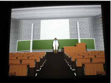
While listening to the virtual sound field, the user is looking at an image of the virtual room in front of him (see Figure 1). He is able to interact with this virtual environment through an appropriate interface (running on a ultra-mobile PC, UMPC). For example, he is able to move himself into the virtual room and the auralized sound is changed accordingly. He can also move the sound sources, change their message (anechoic wave file) and/or their volume. While rapidly switching between
two room’s configurations, the listener is able to appreciate the effect of some acoustical treatments.
Another feature of AURALIAS is the sweet-spot correction system. As the sound reproduction module is based on the VBAP method5, there exists an optimal listening position (the so-called
sweet-spot) in the centre of the loudspeaker arrangement. However, the user in the studio is not
rigorously tight to that specific position, but he is allowed to freely move around it. Therefore, a tracking system based on two laser detectors regularly senses the real position of the listener in the studio and this information is used to correct the VBAP reproduction module accordingly.
Figure 1: View of the screen in the immersion studio.
The users are looking to an image of the virtual room. The front loudspeakers (not apparent on this figure) are situated immediately on the left and right of the screen
3
DESCRIPTION OF THE AURALIZATION SYSTEM
3.1 The acoustical model
As mentioned in the introduction, the auralization of an acoustical space is based on the (directional) room impulse responses (RIRs). In this project, these responses are obtained by a ray-tracing program called Salrev 6.
In architectural acoustics’ problems, one often considers that a unique sound source is present in the room, to compute the room acoustics parameters. This is also the case for the auralization of a theatre, an auditorium or a concert hall, except if one wants to auralize an orchestra, which is quite unusual. On the other hand, several receiving positions are defined in order to test the room acoustics properties on the entire audience surface.
Monophonic (omnidirectional) RIRs (one for each source-receptor pair) are sufficient for the determination of most room acoustics parameters (reverberation time, clarity, definition, ..), but not for auralization. Indeed, auralization must not only render the overall impression of reverberation, but also the source localization and the spatial properties of the sound field. This is why directional RIRs are computed by ray-tracing in several directions around each receptor. These DRIRs are reproduced by the VBAP module as individual contributions to the sound field. Also in headphones’ reproduction, each DRIR is convolved with the adequate HRTF in order to localize its contribution in the listener’s virtual sound environment.
The question about the number of computed DRIRs was asked early in the conception of the auralization system. This question is discussed in reference2. Since then, we have mainly used two types of sets: 6 or 26 DRIRs. The first set corresponds to the division of the listening sphere into 6 solid angles: four are situated around the horizontal plane, between +45 and –45 degrees in elevation and with an azimuth extent of 90 degrees. These four solid angles collect the energy of the sound rays reaching this receiving position, leading to four directional echograms and, finally, to four DRIRs. Each directional response is attributed to the central direction of the solid angle for auralization cues. These four solid angles therefore create the DRIRs called frontal, rear, left and
right. To complete the sphere and the set of solid angles, the remaining cone around elevation +90
deg. creates the up directional RIR and the same kind of cone is defined at the bottom, around elevation –90 deg. By analogy with this procedure, the set of 26 solid angles is defined as illustrated in Figure 2. 67 5 22 5 0 -67 5 -22 5.
Figure 2: The set of 26 solid angles defined around the listener’s head to compute the 26 directional room impulse responses.
The set of 26 DRIRs of course provides a better resolution in the spatial localization of the contributions to the sound field than the set of 6, at the cost of a longer computing time for the same accuracy in the results. However, it is still not sufficient to correctly reproduce the direct sound field. Therefore, a mirror source module has been added to the sound ray program in order to compute the precise localization of the real source and the specular reflections up to a pre-defined order. The question now arises about the value of this pre-defined order: we generally not exceed the 3rd order in our applications, while we have not really conducted subjective experiments to confirm that this is sufficient. However, one must be aware that increasing this maximum order also increases the number of image sources to be computed and auralized, and both aspects are important in a real-time auralization in which these sources must be re-computed each real-time the real sources and/or the receiving position are modified.
In most auralization systems, the real and image sources’ contributions are computed in real-time (up to a maximum order), while the remaining contributions are assembled into a monophonic (omnidirectional) RIR. The latter is furthermore often approximated by some room acoustics’ model to allow its computation in real-time. In AURALIAS, we have decided to keep the quality of auralization as high as possible, for the largest category of rooms that can be met in practice, as the system is conceived for professional applications, especially for architects and acousticians. For example, some room geometries create flutter echoes that are badly reproduced by monophonic RIRs.
We therefore decided to keep complete directional RIRs, but this decision of course has a price: complete DRIRs cannot be re-computed in real-time, in particular in significantly reverberant rooms where their length may reach some seconds. Two reasons can explain this:
- the sound ray process is much time-consuming if it is conducted to compute echograms which are some seconds long,
- the conversion of these directional echograms into DRIRs is also time-consuming.
The solution that is presently adopted is to run the sound ray program Salrev off-line, which means before the auralization session, for a great number of sources’ and receptors’ positions. The resulting DRIRs are then copied into a database from which the auralization system can extract in real-time the closest responses for each new position of source and/or receiving position.
3.2 Signal processing and sound reproduction systems
As mentioned in the introduction, the sound reproduction system of AURALIAS is realized by a set of loudspeakers fed by the signals computed by a VBAP module. Another possibility is to use a binaural reproduction through headphones.
In the VBAP system, each image source (included the real source, which is the zero-order mirror source) and each directional RIR contributions are attributed to the adequate pair (in 2D VBAP) or triplet (in 3D VBAP) of loudspeakers. The amplification gain of each loudspeaker of the pair or the triplet is determined to create the phantom source in the correct direction, and also to keep the power of the contribution unchanged.
At the end of the process, once all image sources and all DRIRs have been localized, an impulse response hli[n] is attributed to each loudspeaker Li. This response is the sum of all
amplitude-corrected DRIRs contributing to the ith VBAP channel. The main real-time signal processing task of the auralization system is then to operate the convolution of each loudspeaker’s impulse response with the anechoic signal san[n] emitted by the source:
(1)
]
[
]
[
]
[
n
s
n
h
n
s
i=
an⊗
liThis convolution task is a permanent one, as long as there are samples in the anechoic signals and there’s no modification to the virtual acoustical space. It is implemented with a frequency block segmented convolution based on the overlap-add method4.
Each new modification in the acoustical space (the displacement of a source or the receiving position, or whatever) implies the re-computing of the responses hli[n] . This operation must be
operated in real-time, in fact in a very short time, ideally not perceptible by the listener. To speed up the process, only the image sources’ contributions are re-computed in real-time (the DRIRs are copied from a database, see section 3.1).
Despite this, there may subsist a small delay, depending on the complexity of the virtual space and on the computer on which the application is running. During this delay, the sound reproduction continues with the old impulse responses in (1), until the new ones are ready to be convolved. A visual signal informs the user that his modifications are being treated and another one appears when the modifications are active.
In the binaural system, each image source and each directional RIR contributions are first convolved with the adequate HRTFs (depending on the direction of incidence of the contribution). Two convolutions are necessary for each contribution: with the left HRTF and with the right HRTF. The left contributions are then summed together to give hleft[n], and the same for hright[n]. Both are
then convolved with the anechoic signal of the source, as in (1). Each new modification implies not only the re-computing of the mirror sources’ impulse responses and the extraction of the adequate DRIRs from the database, but also their convolution with the corresponding HRTFs.
3.3 Hardware
The present prototype of the auralization system runs on a PC under Windows Vista 64 bits whose main specifications are:
• CPU (X2) : Intel Xeon E5520 – 2,26 GHz • GPU : Leadtek PX9600GT – nVidia 9600GT • Ram : 12Go
A Toshiba TDP – EX 20 data projector is used for the projection of virtual rooms in front of the users. The sound reproduction is provided by six Far XMD range Digital active three way loudspeakers, those loudspeakers being driven by an EDIROL AudioCapture FA – 101 sound card. The user interface is deported on a Samsung Q1 Ultra UMPC.
An interesting option in AURALIAS is the possibility for the user to listen to his own voice in the virtual room, while speaking in a microphone (SHURE PG30 wireless headsets microphone). In this option, the direct sound must be excluded from the DRIRs (only the reflections are simulated).
4
AURALIZATION OF INDUSTRIAL HALLS
4.1 Specificities of industrial noise problems
What are the differences between architectural acoustics and industrial noise problems that bring new challenges to auralization ?
First of all, the availability of anechoic recordings. In the auralization of theatres and concert halls, speech signals or music samples are used as anechoic signals emitted by the source. This kind of signal is quite easily found, or can be recorded in an anechoic room. The speaker or the particular musical instrument is not of major importance. On the other hand, the sound sources creating noise in an industrial hall are really specific and it is hardly probable that anechoic recordings are available for a specific machine. Also, most of these sound sources are so large or so polluting that bringing them into an anechoic chamber is often simply not possible.
In the application described in the next section, we have used pseudo-anechoic recordings: “pseudo” means that these recordings have been realized in-situ, but in the near field, the closest to the machine as possible. The room in which the machine was operating was not significantly reverberant.
Another problem with these recordings is the possible directivity of the sound emission. This problem has not been addressed in this paper, in which we assume that the sound sources are isotropic.
Secondly, several sound sources are usually present in an industrial hall, contrary to most problems in architectural acoustics. The challenge is here quite clear, referring to section 3.2: since more sources are present, the number of operations increases after most modifications in the acoustical space. For example, the displacement of the receiving position requires the actualisation of a greater number of image sources (some may become invisible, other could appear). The challenge is therefore to keep real-time operations when passing from one source to five sources, or even more.
Thirdly, industrial halls are usually more reverberant than theatres or concert halls, which implies longer DRIRs and, therefore, longer convolutions. The challenge is again to keep real-time operations.
A fourth specific character is the quite regular geometry of several industrial halls. Rectangular and reverberant enclosures with flat walls are prone to create flutter echoes in certain directions. Also, the shape of these halls is often disproportionate, with their height much smaller than the horizontal dimensions. This may lead to directional RIRs significantly different along the up-down direction
than along the horizontal ones. Figure 4 illustrates this difference: see the blue and brown directional echograms, which decrease faster than the other ones, even if the effect is attenuated in this example by the sound scattering operated by some surfaces.
This however reinforces our decision to keep using directional RIRs instead of monophonic (omnidirectional) RIRs, since the latter are not able to take this effect into account in the auralization.
A last specific requirement of industrial noise problems would be to auralize the absolute noise levels, to test annoyance. This would imply to establish a kind of sound level calibration in the auralization system, which is not yet implemented. Though this aspect could be important for further applications, it has not been tested in the present study.
4.2 Application
We have simulated the room acoustics of a joinery workshop, in which up to five noisy machines can be operated at the same time: a circular saw (1), a spindle moulding-machine (2), a compressor (3), a surfacing machine (4) and a planning-machine (5). The numbers in parenthesis refer to the plane view of the hall in Figure 3. Its dimensions are 30m long, 18m large and 6.1 m in height.
11th receptor
Figure 3: Plane view of the joinery workshop. The red spots are the 5 sources’ positions, and the blue ones are the pre-defined receptors. The green symbol represents the position of the
virtual listener during auralization, with its viewing direction. This position and the orientation of the viewing direction can be changed in real-time.
The floor, the walls and the ceiling are in concrete, which make the space quite reverberant : around 4s at low frequencies, 3s at 1kHz and 2s at 4kHz. Daylight enters the halls through six large roof windows, which are also apparent in Figure 3 (the six rectangular surfaces regularly spaced along the left-right direction). The entrance of the hall is in the lower left corner of the figure. Also, two large sliding doors are included in the left wall, to allow vehicles to enter the hall. These doors
have been closed and no vehicle was present in the simulations. Finally, some tables and pieces of furniture complete the surfaces inside the hall.
The sound ray program was run with 19 pre-defined receiving positions (the blue and green spots in the figure). Each sound source randomly emits 106 rays, which lead to a satisfying statistical accuracy (error less than 0.2 dB on the global SPL and less than 3dB for most values of the echogram). The computing time was around 60 minutes to obtain all the directional echograms for all source-receptor pairs (there are 6 solid angles, defining six directional echograms in eight frequency bands for each source-receptor pair). Figure 4 shows some results obtained for the source nb.1 and the 11th receptor.
Figure 4: Directional echograms computed in the joinery workshop, in the 63Hz octave band, for the source in position 1 and the 11th receptor. The listener is supposed to look horizontally to the left, so the “front” echogram refers to this direction. Image sources up to the 3rd order
are NOT included in this echogram.
The image sources up to the 3rd order (including the real sources of zero-order) are not included in the directional echograms. The reason is that their contributions are computed in real-time during the auralization session and added to the DRIR contributions, as explained in section 3.
An auralization session was then organized to judge the performance of the system. It was intended to test the ability of the auralization system to answer in real-time to the requirements of the user. These requirements first included the displacement of the virtual listener in the horizontal plane, the modification of his viewing direction (head orientation), some operations related to the sources (start/stop/change volume or message) and switching from one room’s configuration to another. With the hardware described in section 3.3, all these operations could been realized in pseudo-real-time, meaning that the delays were nearly unperceivable for the user of the system. In particular, the convolutions with complete DRIRs as long as 5 seconds were not an obstacle to reach this objective, even when the five sources were running at the same time. Only when the displacements of the virtual listener were abnormally fast could some artefacts be audible.
The displacement of the sources have also been tested. Of course, in this hall where the machines are in a fixed position, this operation is not really realistic (except if the source is the listener himself!). But the conclusions were the same about the pseudo-real-time performance. In particular, the auralization of the user’s own voice in the workshop seemed quite satisfying.
5
CONCLUSION AND ACKNOWLEGMENTS
An auralization system has been applied to an industrial noise problem, showing its ability to take up the new challenges introduced by this kind of problem. Future works should be devoted to the testing of the quality of the auralization.
The AURALIAS research project is supported by the Region of Wallonia (Belgium) under contract number 616416.
6 REFERENCES
1. M. Vorländer. Auralization, Springer-Verlag (2008).
2. J.J. Embrechts, N. Werner and S. Lesoinne, Computation of Directional Impulse Responses in Rooms for Better Auralization, Convention paper nb.6498 of the 118th convention of the Audio Eng. Soc., Barcelona (2005).
3. AURALIAS website: www.auralias.be
4. L. Bos and J.J. Embrechts, An interactive and real-time based auralization system for room acoustics, implementing directional impulse responses and multiple audio reproduction modules for spatialization (the AURALIAS project), Proc. of NAG/DAGA 2009 conference, Rotterdam (2009).
5. V. Pulkki, ‘Virtual sound source positioning using vector base amplitude panning’, J.Audio.Eng.Soc.45 456-466 (1997).
6. J.J. Embrechts, ‘Sound field distribution using randomly traced sound ray techniques’, Acustica 51 288-295 (1982).