Journal of Fundamental and Applied Sciences is licensed under a Creative Commons Attribution-NonCommercial 4.0 International License. Libraries Resource Directory. We are listed under Research Associations category.
STUDY OF AN ABSORPTION MACHINE FOR AN AMMONIA-WATER SYSTEM DECENTRALIZED TRIGENERATION
A.M.M. Rashidi1, B.A. Habibzadeh2,* and C.S.S. Rezaie3
1
Associate Professor of Mechanical Engineering, Mechanical Engineering Department, Engineering Faculty of Bu-Ali Sina University, Hamedan, Iran
2
Department of Mechanical Engineering, Miandoab Branch, Islamic Azad University, Miandoab, Iran
3
Graduate Student of Mechanical Engineering, Mechanical Engineering Department, Engineering Faculty of Bu-Ali Sina University, Hamedan, Iran
Received: 07 December 2015 / Accepted: 27 Mars 2016 / Published online: 01 May 2016
ABSTRACT
This paper deals with Study of an absorption machine for an ammonia-water system decentralized trigeneration. The effects of evaporator, absorber and boiler temperature on the coefficient of performance of this cycle investigate. Simulation results show that with increasing the evaporator and absorber temperature the coefficient of performance increased and decreased, respectively. By increasing boiler temperature the coefficient of performance is constant.
Keywords: absorption system; trigeneration; coefficient of performance.
Author Correspondence, e-mail: [email protected]
doi: http://dx.doi.org/10.4314/jfas.v8i2.25
ISSN 1112-9867
Nomenclature ∆E Exergy losses 2 [ ] A m area Subscripts [ ] E kW efficiency C condenser 1 [ . ]
m kg sɺ − mass flow rate EV evaporator
[ ]
P kPa pressure A absorber
[ ]
Q kW heat load ES solution heat exchanger
[ ]
T C temperature ER refrigerant heat exchanger
3 1
[m kg ]
ν −
specific volume P pump
[ ]
W kWɺ Work rate D desorber
1
[ ]
UA W K− total heat transfer coefficient R rectifier
Greek letters C turbine
η
efficiency o environment state1. INTRODUCTION
In recent years, in many industrial processes such as food processing, preservation and transport, comfort cooling, commercial and industrial air conditioning, manufacturing, energy production, health and recreation, the need for simultaneous production of electric power and refrigeration at low temperatures has increased remarkably. Using the combined cycles is one of the ways to decrease the negative environmental impact of the energy resources, lower the fuel consumption and improve the total energy conversion efficiency of the power plants. As fossil fuels are terminate and the fuel prices are increasing, exploiting inexpensive energy sources like solar, geothermal, waste heat from gas and steam turbines and biomass has got a lot of attention.
Most of the conventional vapor compression systems use chlorofluorocarbon refrigerants (CFCs). Depletion of the ozone layer is the reason that the use of the CFCs is restricted. Therefore, other systems those operate with environmentally friendly fluids should be replaced. One of the systems that can use these energy sources to convert to useful
refrigeration is absorption refrigeration system (ARS). Although the absorption cycles have low COP values, by considering the problems that vapor compression cycles cause to the environment, ARSs have become popular. When there is a source of inexpensive thermal energy at a temperature of 100 to 300ºC, absorption refrigeration system becomes economically attractive. An absorption cycle needs thermal energy to power the absorption machine and the chilled water from the absorption machine feeds the plant’s condenser, which is useful for both systems. On the other hand, using mixed working fluids can reduce the exergy loss in heat addition process of the thermal power cycles. The reason is that the temperature difference between working fluid and variable temperature heat sources remains constant during boiling process.
For the first time, in the early 1950s, Maloney et al. [1] studied applying a mixture of
ammonia and water as a working fluid in power cycles. Kalina [2] was the first one who
proposed the exploiting of ammonia-water mixtures as the working fluids in the bottoming cycle of a combined cycle power plant. After that researchers have studied the use of the
ammonia-water mixtures in different cycles. [3-12] Srikhirin et al. [13] investigated
absorption refrigeration technology by studying various types of ARSs, working fluids, and improvement of absorption processes. The ammonia-water cycle was analyzed by Sun from different points of view [14-16]. In one of his studies, he obtained a mathematical model that allowed the simulation of the process. Moreover, different binary mixtures considered in the absorption refrigeration cycle were analyzed thermodynamically. In another study, to select the operation conditions in order to obtain a maximum performance from the system, he presented a thermodynamic design and performed an optimization of the absorption refrigeration process in order to map the most common cycles for ammonia-water, and water-lithium bromide.
A comprehensive study of various ammonia-water cycles was conducted by Engler et al [17] to compare their performance with operating conditions and design parameters varied over a wide range. Zheng et al. [18] reached higher power and refrigeration output by applying Kalina's technology. They got higher concentration ammonia-water vapor for refrigeration by using rectifier and replacing a condenser and an evaporator between the rectifier and the
second absorber. Fazeli et al. [19] proposed a new combined power and refrigeration cycle which combines the Rankine and absorption refrigeration cycles and uses ammonia-water mixture as the working fluid. They proved that turbine inlet pressure, as well as heat source and refrigeration temperatures have significant effects on the net power output, refrigeration output, an exergy efficiency of the combined cycle.
Koç et al. [20] analyzed A water-ammonia absorption refrigeration system and get to this conclusion that the use of a low temperature heat source imposes some restrictions on the system design, but an economically operating AAR system may be designed by a careful process optimization study. Zhang and Lior [21] proposed a new ammonia-water system for the cogeneration of refrigeration and power. It is found that the cycle has a good thermal performance. Also the results showed that compared with the conventional separate generation of power and refrigeration having the same outputs, the energy consumption of the cogeneration cycle is markedly lower.
2. SYSTEM DESCRIPTION
Figure shows the schematic diagram of the ammonia-water absorption cycle. The waste heat is injected into the generator and the rich solution is separated into the ammonia vapor and the weak solution, then the ammonia vapor is condensed in the condenser. The weak solution and the ammonia liquid are transported through pipelines from the source site to the user site. At the user site the liquid ammonia evaporates in the evaporator to produce cold, or the weak solution absorbs the ammonia vapor in the absorber to produce heat. The rich solution formed in the absorber is then transported back to the generator. Thus there are three liquids which are transported, the ammonia liquid, the weak solution and the rich solution. The heat exchanger at the source site recuperates the heat of the weak solution from the generator, and the heat exchanger at the user site recuperates the heat of the rich solution from the absorber. In this way, the heat energy is stored into the concentration difference of the solutions, and transported at ambient temperatures.
3. DETAILS OF THE MODEL
1- Working fluid after the evaporator is saturated vapor. 2- The condenser outlet state is saturated liquid.
3- The flow across the expansion valve is isenthalpic. 4- There is no loss of pressure in components.
5-There is no loss of heat to the outside.
6- Constant temperature at the exits of each level of the desorber, T6=T16, T9=T18, T10=T11
7-Saturation in the desorption column - Liquid: 6, 10, 15 and 18 - Vapor: 9, 11, 16 and 17
4. MATHEMATICAL MODEL
To developed the mathematical model, the mass, concentration and energy conservation laws (First and Second Laws of the Thermodynamics), was applied in each component of the cycle, where the established control volume for each one of them includes the external reservoir. Every element of the system was analyzed separately. The subscripts of the various properties are relations to the locations indicated in Figure 1. The properties of the working fluids were found at the EES Software. Energy analysis is a thermodynamic analysis technique based on the first law of thermodynamics. The exergy method, known as the second law analysis, calculates the exergy loss caused by irreversibility. The exergy analysis is a powerful tool for thermodynamic analysis of energy-conversion systems. The concept of exergy is extensively discussed in the literatures:
Fig.1. Schematic diagram of the ammonia -water absorption cycle
Refrigerant Heat Exchanger:
The efficiency of the heat exchanger and exergy losses can be given as
2 1 12 1 . rhx T T E T T − = − (1) 12 13 1 2 [( ) ( )] rhx o E T s s s s ∆ = − − + − (2)
Solution Heat Exchanger:
The efficiency of the solution heat exchanger and exergy losses can be given as
7 6 4 6 . shx T T E T T − = − (3) 6 7 4 5 [ ( ) ( )] shx o s w E T m s s m s s ∆ = − − + − (4) Evaporator:
The evaporator refrigeration capacity can be calculated as
(
1 14)
.EV r
Q =mɺ h −h (5)
The exergy losses and efficiency of the evaporator is given as
14 . ( ) in EV EV EV E Q E mcp T T = − (6)
14 1 14 1 ( ) ( ) (1 ) in o EV o EV E T E h h T s s Q T ∆ = − − − + − (7) Absorber:
The absorber capacity and exergy losses can be calculated as
. 2 8 3 ( ). r A s w Q =m h +m h −m h (8) 2 8 3 2 8 3 ( ) ( ) (1 ) in o A s w o s w A A T E h m h m h T s m s m s Q T ∆ = + − − + − − − (9)
The efficiency of the absorber is given as
8 . ( ) in A A A A Q E mcp T T = − (10)
Conservation of mass ammonia is given as
2 s 8 w 3. y +m y =m y (11) Condenser:
(
11 12)
. C r Q =mɺ h −h (12)The efficiency of the condenser and exergy losses are given as
11 . ( ) in C C C C Q E mcp T T = − (13) 11 12 11 12 ( ) ( ) (1 ) in o C o C C T E h h T s s Q T ∆ = − − − − − (14) Pump:
The pump work and exergy losses are given by
(
)
. 4 3 [ ]. r P w W =m m h −h (15) 3 4 3 4 ( ) [ ( )] P w o w P E m h h T m s s W ∆ = − − + +The efficiency of the pump can be given as
3 4 3 ( ) . h b P v P P h h
η
= − − (16) Boiler:The heat input from boiler can be obtained from
6 16 16 15 15
[ ],
D r s
Q =m m hɺ +m h −m h (17)
for a boiler, the efficiency and exergy losses can be estimated by
15 . ( ) in D B B B Q E mcp T T = − (18) 6 16 16 15 15 6 16 16 15 15 ( ) ( ) (1 ) in o B s o s B B T E m h m h m h T m s m s m s Q T ∆ = + − − + − − − (19)
Conservation of mass ammonia is given as
15 15 s 6 16 16.
m y =m y +m y (20)
Purifier:
Conservation of mass ammonia and exergy losses are given as
18 18 w 3 16 16 17 17 15 15.
m y +m y +m y =m y +m y
Rectifier:
Conservation of mass ammonia is given as
9 r f 10 (1+m )y =y +m yf (21) (22) Exhaustion:
Conservation of mass ammonia is given as
17 17 f 10 (1 f ) 9 18 18.
m y +m y = +m y +m y (23)
Parameters used to measure the performance of refrigerators such as coefficient of performance and exergetic efficiency can be expressed as:
, E B P Q COP Q W = + (24) 0 0 (1 ) (1 ) e e exe d p d T Q T T Q W T
η
= − − − + ɺ ɺ ɺ (25) 2 10( ) , total COP V D UA = (26)VD is a new performance index that linked performance coefficient to the total heat transfer.
3. RESULTS AND DISCUSSION
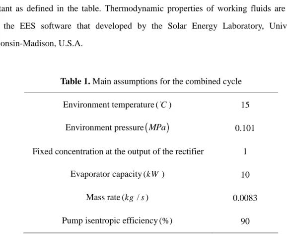
The main assumptions for the simulation of the cycle are summarized in Table 1 and it should be noted that in the analysis, if a single parameter is varied, the other parameters are kept constant as defined in the table. Thermodynamic properties of working fluids are obtained with the EES software that developed by the Solar Energy Laboratory, University of Wisconsin-Madison, U.S.A.
Table 1. Main assumptions for the combined cycle
Environment temperature (C ) 15
Environment pressure
(
MPa)
0.101Fixed concentration at the output of the rectifier 1
Evaporator capacity (kW ) 10
Mass rate (kg s / ) 0.0083
Pump isentropic efficiency (%) 90
Effect of evaporator temperature on the COP, VD and UA
When the evaporator temperature increases, the coefficient performance increases because the heat load in evaporator increases (Fig. 2.). With increasing the evaporator temperature the total heat transfer coefficient increasing because the temperature difference increases and evaporator can receive more heat. But with this increasing, VD decrease because VD has opposite relation with UA.
Fig.2. Effects of evaporator temperature on the efficient coefficient and total heat transfer coefficient
Effect of absorber temperature on the COP
By increasing the absorber temperature, COP decrease because the pressure of the flow increase and eventually work of the pump increases. By this increasing total heat transfer coefficient decrease because different temperature between inlet and outlet flow decrease that can be seen at Fig. 3.
Fig.3. Effects of absorber temperature on the efficient coefficient and total heat transfer coefficient
As illustrate at Fig. 4 by increasing the boiler temperature the total heat transfer coefficient increase correspondingly. As shown at Fig. 5 And Fig. 6 With increasing in total heat transfer, coefficient of performanc increased because more heat can transfer in heat exchanger, and by increasing the performance coefficient the VD increases.
Fig.4. Effects of boiler temperature on the efficient coefficient and total heat transfer coefficient
Fig.5. Effects of total heat transfer coefficient of the solution heat exchanger on the efficient coefficient and VD
Fig.6. Effects of total heat transfer coefficient of the refrigerant heat exchanger on the efficient coefficient and VD
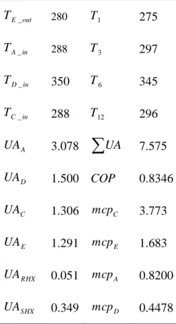
As shown at Fig. 7 by increasing the tempreture of the intrance flow to the boiler the heat load increase so eventually the efficient coefficient increase. By compering the figures we can obtain the optimal conditions that showed in Table 2.
( )
_ o
TD in C
Table 2. Optimal results for the cycle _ E out T 280 T1 275 _ A in T 288 T3 297 _ D in T 350 T6 345 _ C in T 288 T12 296 A UA 3.078
∑
UA 7.575 D UA 1.500 COP 0.8346 C UA 1.306 mcpC 3.773 E UA 1.291 mcpE 1.683 RHX UA 0.051 mcpA 0.8200 SHX UA 0.349 mcpD 0.4478 Exergy analysisFig. 8. shows variations of the exergetic efficiency (
η
exe) with the desorber temperature. The exergetic efficiency decrease with an increase in the desorber temperature for the case of35o C
T = C and TE =35oC ,. As the efficiencies of the first and second laws are examined in general, it is seen that
η
exe increases up to a desorber temperature of 90oC . At the higherdesorber temperatures,
η
exe decreases gradually. The reason for this is that the increase in the desorber temperature negatively influences theη
exe value as seen from Eq. (18). The system has better exergetic efficiencies when operating with a low condenser temperature and the high evaporator temperature within some desorber temperature ranges. Within its own desorber temperature range, the exergetic efficiency of the system initially increases and declines continuously as the desorber temperature increases. This is because a higher desorber temperature means more external input exergy supplied to the system, even though the lattercan drive more water vapor from ammonia-water solution to create cooling. It also generates more exergy losses in the desorber, condenser and absorber as their average temperatures rise up. This contributes negatively to the exergetic efficiency of the system. Since this negative effect of increasing the desorber temperature is more dominant on the exergetic efficiency of the system, it decreases with increasing desorber temperature, while the COP stays almost constant.
Fig.8. Variation of
η
exewith desorber temperature at different condenser and evaporator temperatures6. CONCLUSION
In this study, the first and the second law of thermodynamics is applied to an absorption machine for an ammonia-water system. The COP, VD and
η
exe are calculated from the thermodynamic properties of the working fluids at various operating conditions by using the developed mathematical model. The results show that COP of the cycle increases with increasing boiler and evaporator temperatures, but decreases with increasing condenser and absorber temperatures. Three components that obtained the highest exergy loss are thegenerator, the absorber and the evaporator. In the parametric analysis of the system, it is shown that a low condenser temperature yields a higher cooling COP and higher exergetic efficiency. The system operating with relatively high evaporator temperatures has better cooling COP and experiences smaller exergetic efficiency than the one having low evaporator temperatures. Increasing the generator temperature can improve the cooling COP of the absorption system, but as the heat source temperature further increases, the COP of the system levels off. This negative effect of increasing the heat source temperature is more dominant on the exergetic efficiency of the system. Consequently, this negative result on the exergetic efficiency and the COP removes the beneficial effect of a high heat source temperature. Finally, this study draws attention to a detailed thermodynamic analysis (first and second law) and leads the way to improve thermal systems and their components.
7. REFERENCES
[1] Maloney JD and Robertson RC. Thermodynamic Study of Ammonia-Water Heat Power Cycles. ORNL Report No. CF-53-8-43, Oak Ridge, TN, 1953.
[2] Kalina AI. Combined-Cycle System with Novel Bottoming Cycle. ASME J. Eng. Gas Turbines Power, 1984, 106, 737–742.
[3] Murugan RS, Subbarao PMV. Effective utilization of low-grade steam in an ammonia—water cycle. Proceedings of the Institution of Mechanical Engineers, Part A: J. Power and Energy. 2008, 222(2): 161-166.
[4] Murugan RS, Subbarao PMV. Efficiency enhancement in a Rankine cycle power plant: Combined cycle approach. Proceedings of the Institution of Mechanical Engineers, Part A: J. Power and Energy. 2008, 222(8): 753-760.
[5] Moghimi MA, Talebizadeh P and Mehrabian MA. Heat generation/absorption effects on MHD natural convection flow over a sphere in a non-Darcian porous medium. Proceedings of the Institution of Mechanical Engineers Part E, J. Process Mechanical Engineering. 2011, 225 (1): 29-39.
[6] Mehrabian MA and Shahbeik AE. Thermodynamic modelling of a single-effect LiBr- H2O absorption refrigeration cycle. Proceedings of the Institution of Mechanical Engineers Part E:
J. Process Mechanical Engineering. 2005, 219(3): 261-273.
[7] Mone CD, Chau DS and Phelan PE. Economic feasibility of combined heat and power and absorption refrigeration with commercially available gas turbines. Energy Convers Manage. 2001, 42, 1559–1573.
[8] Thorin E. Thermophysical Properties of Ammonia-Water Mixture for Prediction of Heat Transfer Areas in Power Cycles, International Journal of Thermophysics. 2001, 22(1): 201-214.
[9] Patek J and Klomfar J. Simple Functions for Fast Calculations of Selected Thermodynamic Properties of the Ammonia-Water System. International Journal of Refrigeration. 1995, 31(4): 228-234.
[10] Soleimani AG. Simple Equations for Predicting Entropy of Ammonia-Water Mixture. International Journal of Engineering. 2007, 20(1): 97-106.
[11] Xu F and Goswami DY. Themodynamic Properties of Ammonia-Water Mixtures for Power-Cycle Applications. Energy. 1999, 24(6): 525-536.
[12] Liu M and Zhang N. Proposal and Analysis of a Novel Ammonia-Water Cycle for Power and Refrigeration Cogeneration. Energy. 2007, 32(6): 961-970.
[13] Srikhirin P, Aphornratana S and Chungpaibulpatana S. A review of absorption refrigeration technologies. Renew. Sustain Energy Rev. 2001, 5, 343–372.
[14] Sun DW. Computer Simulation and Optimization of Ammonia-Water Absorption Refrigeration Systems. Energy Sources,. 1976, 17, 211-221.
[15] Talbi MM and Agnew B. Exergy analysis: an absorption refrigerator using lithium bromide and water as working fluids. Thermal Engineering. 2000, 20, 619–630.
[16] Zhang XJ and Wang RZ. A new adsorption–ejector refrigeration and heating hybrid system powered by solar energy. Thermal Engineering. 2002, 22, 1245–1258.
[17] Kilic M and Kaynakli O. Second law- based thermodynamic analysis of water-lithium bromide absorption refrigeration system. Energy. 2007, 32, 1505–1512.
[18] Zheng D, Chen B and Qi Y. Thermodynamic Analysis of A Novel Absorption Power/Cooling Combined Cycle. Proceedings of ISHPC’02. Applied Energy. 2006, 83, 311–323.
[19] Fazeli SA , Rezvantalab H and Kowsary F. Thermodynamic analysis and simulation of a new combined power and refrigeration cycle using artificial neural network thermal science. Thermal Science. 2011, 15(1): 29-41.
[20] Koç A, Bulgan AT and Öztürk NA. Design and analysis of a water-ammonia absorption refrigeration system.Proceedings of the Institution of Mechanical Engineers, Part A: J. Power and Energy. 2000, 214(5): 449-454.
[21] Zhang N and Lior N. Development of a Novel Combined Absorption Cycle for Power Generation and Refrigeration. ASME Journal of Energy Resources Technology. 2007, 129(3): 254-265.
How to cite this article:
Rashidi A.M.M, Habibzadeh B.A. and Rezaie C.S.S. Study of an absorption machine for an ammonia-water system decentralized trigeneration. J. Fundam. Appl. Sci., 2016, 8(2),