HAL Id: hal-02945813
https://hal.archives-ouvertes.fr/hal-02945813
Submitted on 22 Sep 2020
HAL is a multi-disciplinary open access
archive for the deposit and dissemination of
sci-entific research documents, whether they are
pub-lished or not. The documents may come from
teaching and research institutions in France or
abroad, or from public or private research centers.
L’archive ouverte pluridisciplinaire HAL, est
destinée au dépôt et à la diffusion de documents
scientifiques de niveau recherche, publiés ou non,
émanant des établissements d’enseignement et de
recherche français ou étrangers, des laboratoires
publics ou privés.
Building a CAD system for educational purpose based
only on a mesh tool and a FE solver
Yvan Lefèvre, Julien Fontchastagner, Frédéric Messine
To cite this version:
Yvan Lefèvre, Julien Fontchastagner, Frédéric Messine. Building a CAD system for educational
pur-pose based only on a mesh tool and a FE solver. 15th Conference on the Computation of
Electromag-netic Fields - COMPUMAG 2005, Nov 2005, Shenyang, China. �hal-02945813�
Building a CAD system for educational purpose based only on a mesh tool and a FE
solver
Y. Lefèvre, J. Fontchastagner, F. Messine
LEEI-ENSEEIHT-INPT, UMR CNRS 5828 2, Rue Camichel, BP 7122, Toulouse, Cedex
31071 France [email protected]
Abstract— the article discusses the use of FEM software to help
lecturer to teach design of electrical machines. Nowadays, lecturers have less and less time to teach the design of electrical machines. Special tools based on FEM can help them in this task. In past years, such tools needing sophisticated environments have been realized for designers in industry. Assuming minimum equipment, requirements, guidelines and a realization of a specific tool are presented.
I. INTRODUCTION
In one hand, we know that there is a growing problem to educate students engaged in an electrical engineering curriculum. Electrical engineering students have to achieve a very large spectrum of knowledge in science and technology ranging from fundamental sciences such as mathematics, physics (electromagnetism, material sciences, and mechanics) to applied science like control, data processing, electronic, and power electronics. So students in electrical engineering who want to be expert in electrical machines have less and less time to study what should be their main subject: the design of electrical machines.
In the other hand, we know that industry is lacking in designers of electrical machines because we are witnessing a growing development of the applications of electrical motors and actuators. Industry wants them more and more efficient and well adapted to their applications. So design of electrical machines becomes a more and more difficult task.
We think that finite element method (FEM) should be more and more used in academic area to help lecturers to teach electrical machine design. This paper presents a discussion about the use of CAD system based on finite element code for teaching electrical machines and a realization of such a system to help teaching design.
II. FEM AND TUTORIAL ELECTRODYNAMICS
Commercial finite element (FE) softwares are more and more used in industry. They are more and more introduced in academia. These softwares can be a very good help to teach electromagnetism and FEM which is now one of the most powerful tool in electrical engineering. They are very useful to help to explain many notions such as leakage flux, traveling field, air-gap induction, slots effects. They, especially those who can take into account the movement of the rotor, can also be a valuable help to analyze the electromechanical behavior
of classical machines such as synchronous machines, induction machines or reluctance motors [1].
But their main drawback for students is that most of them are not easy to use and students must spend some hours, days or weeks before being familiar with them. It is due to the fact that these softwares are of general purpose. They can solve many types of electromagnetic problem, for several different kinds of actuators or electrical machines. So to perform a simulation it is necessary to do several tasks (drawing, meshing, solving and post-processing) which are not very easy for beginners.
For some tutorials proposed to students, a tool that can do these different tasks automatically has to be provided. For instance, students may be asked to analyze the validity domain of an analytic model for sizing permanent magnet motors. They have not to worry about how to draw, how to mesh, how to solve and how to compute flux. They only have to concentrate on their problem.
In the past, many searchers have developed such a tool for designers in industry. Most of these tools are developed in a special environment depending on some particular FE software. There is for instance a parametric environment which has been developed around OPERA-2D [2], a design process has been built up around FLUX-2D [3] and a way of building an integrated cad system around EFCAD has been attempted [4].
III. ATOOLFORTEACHINGELECTRICALMACHINEDESIGN
A.Assumptions
We are trying to specify the requirements of such a tool from the point of view of a user with the minimum tools at his disposal. So, we don’t try to adapt it to any kind of up-to-date methods which require special environment. The environment considered are common operating system like UNIX, Linux or windows (in fact dos).
We based our discussion by assuming only the existence of a meshing tool that can be called from a language like FORTRAN or C and a module that can solve a 2D magnetic problem formulated in potential vector and compute the flux in windings.
We assume that the meshing tool is capable to mesh quadrangular regions of any kind: contour lines can be arc of
circle or segment of straight line.
We assume that the solver has a standard data base. As input, it needs: a table of node coordinates; a table of element location; a table of element material properties; a table informing which winding each element belongs to; a table of nodes with homogenous Dirichlet conditions (Az=0), a table of nodes with odd or even cyclic boundary conditions. And as output, it gives: the third component of vector potential (Az) on each node. The flux is calculated from Az on each node and from the table which relates elements to windings.
B.Requirements
The main requirement of the tool is that it can consider several types of machines: induction motor, synchronous motor, reluctance motor. The motors can have several kinds of geometry configuration (the rotor can be outside or inside the stator), several kinds of structure (the numbers of phases, of pair of poles and slots can vary); several kinds of winding are considered (concentrated or distributed). It can consider machines of any dimensions according to the fact that these dimensions are compatible between themselves and with the type of the machines, their configuration and their structure.
C.From geometric and material data to the mesh.
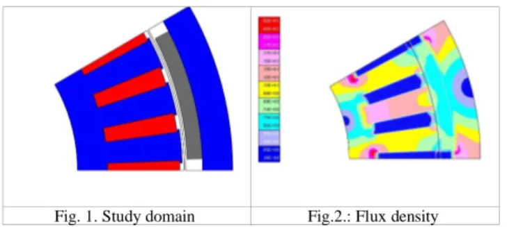
The first step is to divide the study domain (Fig. 1) in quadrangular regions (not shown) characterized by contour lines, a material property and the number of the winding to which it belong if necessary.
A number of nodes are affected to each line of each region. This affectation is done automatically according to a simple law that can be described like this: the number of nodes on the lines (arc) in the air-gap is equal to twice the number of slots harmonics considered multiplied by the number of slots in the study domain. Then the numbers of nodes on other lines are calculated in function of their distance from the air-gap.
When all the data structures of each region are filled, the mesh tool is called to mesh each region. During this process the tables affected to each element are filled from the physical characteristics of each region. The elements and nodes of all elements are collected together and then renumbered in order to reduce the bandwidth of the stiffness matrix. The homogenous Dirichlet conditions are assigned to the nodes on the frontier of the study domain located at the minimum radius and maximum radius, cyclic boundary conditions that can be
odd or even are assigned to those located at the minimum angle and maximum angle.
D.Computation of characteristics and performances
At a design stage, waveforms of the flux and the feeding currents of the electrical machines are assumed to be ideal. So the performances or the characteristics of electrical machines can be deduced from flux computations. For instance, for a permanent magnet machine with sinusoidal waveforms, the no-load flux in windings due to magnets and the flux in windings for two types of load currents (longitudinal and transversal) are computed. From these three values, the torque, flux and voltage can be calculated for any type of sinusoidal currents.
E.Verifications
To allow the students verify their results, the tool can be linked to existing FE softwares. This can be done at different stages with the help of files: drawing files (DXF), pre-mesh files [4] describing the regions, mesh files with or without the potential on each node.
The figure 2 shows flux density displayed by our own general purpose FE software. To obtain these results we have only given the sizes of the different parts of the motor and the material data. Our tool computes automatically the vector potentials on nodes and the flux in windings for any load currents.
IV. CONCLUSIONS
In this paper, we have discussed about the use of FEM for help to teach applied electrodynamics. We have presented the requirements of a tool adapted to tutorial designs of electrical machines. Guidelines to build such a tool are presented, a prototype has been realized and the first results obtained have been presented.
REFERENCES
[1] N. Sadowski, Y. Lefèvre, M. Lajoie-Mazenc and J. Cros, "Finite element torque calculation in electrical machines while considering the movement," IEEE Transactions on Magnetics. vol. 29, n°2, pp. 1410-1413, March 1992.
[2] C. F. Parker, J. K. Sykulsi, and S.C. Taylor, "Parametric Environment for EM Computer Aided Design," IEEE Transactions on Magnetics. vol. 32, n°3, pp. 1433-1436, May 1996.
[3] F. Wurtz and al., "Methodological Guidelines for the use of Analytical and Numerical Models in a Design Process of an Electromagnetic Device," IEEE Transactions on Magnetics. vol. 34, n°5, pp. 3411-3414, September 1998.
[4] C. Henaux, S. Astier, Y. Lefèvre and M. Lajoie-Mazenc, "First steps towards full integrated cad system for electrical machines," Compel. vol. 14, n°4, pp. 151-155, 1995.