HAL Id: hal-01522928
https://hal.archives-ouvertes.fr/hal-01522928
Submitted on 15 May 2017
HAL is a multi-disciplinary open access
archive for the deposit and dissemination of
sci-entific research documents, whether they are
pub-lished or not. The documents may come from
teaching and research institutions in France or
abroad, or from public or private research centers.
L’archive ouverte pluridisciplinaire HAL, est
destinée au dépôt et à la diffusion de documents
scientifiques de niveau recherche, publiés ou non,
émanant des établissements d’enseignement et de
recherche français ou étrangers, des laboratoires
publics ou privés.
Building a CAD system for educational purpose based
only on a mesh tool and a finite elements solver
Yvan Lefèvre, Julien Fontchastagner, Frédéric Messine
To cite this version:
Yvan Lefèvre, Julien Fontchastagner, Frédéric Messine. Building a CAD system for educational
pur-pose based only on a mesh tool and a finite elements solver. IEEE Transactions on Magnetics, Institute
of Electrical and Electronics Engineers, 2006, 42 (4), pp.1483-1486. �10.1109/TMAG.2006.871435�.
�hal-01522928�
Building a CAD System for Educational Purpose
Based Only on a Mesh Tool and a
Finite Elements Solver
Yvan Lefévre, Julien Fontchastagner, and Frédéric Messine
LEEI-ENSEEIHT-INPT, UMR CNRS 5828, Toulouse Cédex 31071, France
The article discusses about the use of finite elements method (FEM) software in order to help lecturer to teach design of electrical ma-chines. Nowadays, lecturers have less and less time to teach the design of electrical mama-chines. Special tools based on FEM can help them in this task. For the past years, such tools needing sophisticated environments have been realized for designers in industry. Assuming minimum equipment, requirements and guidelines for the realization of a specific tool are presented.
Index Terms—Design, electrical machines, finite elements method (FEM).
I. INTRODUCTION
O
N the one hand, we know that there is a growing problem to educate students engaged in an electrical engineering curriculum. Electrical engineering students have to achieve a very large spectrum of knowledge in science and technology ranging from fundamental sciences such as mathematics, physics (electromagnetism, material sciences, and mechanics) to applied science like control, data processing, electronic, and power electronics. Thus students in electrical engineering who want to be expert in electrical machines have less and less time to study what should be their main subject: the design of electrical machines.On the other hand, we know that industry is lacking in designers of electrical machines because we are witnessing a growing development of the applications of electrical motors and actuators. Industry wants them more and more efficient and well adapted to their applications. Thus the design of electrical machines becomes a more and more difficult task.
We think that finite elements method (FEM) should be more and more used in academic area to help lecturers to teach elec-trical machine design. This paper presents a discussion about the use of CAD system based on finite elements code for teaching electrical machines and a realization of such a system to help teaching design.
II. FEMANDTUTORIALELECTRODYNAMICS
Commercial finite elements (FE) softwares are more and more used in industry. They are more and more introduced in academia. These softwares are of a very efficient help to teach electromagnetism and FEM which is now one of the most powerful tool in electrical engineering. They are very useful to explain many notions such as leakage flux, traveling field, air-gap induction, slots effects. They (especially those who can take into account the movement of the rotor) can also be a valuable help to analyze the electromechanical behavior of
classical machines such as synchronous machines, induction machines or reluctance motors [1].
But their main drawback for students is that most of them are not easy to use and students must spend some hours, days or weeks before being familiar with them. It is due to the fact that these softwares are of general purpose. They can solve many types of electromagnetic problem, for several different kinds of actuators or electrical machines. Thus, in order to perform a sim-ulation it is necessary to do several tasks (drawing, meshing, solving, and post-processing) which are not very easy to per-form by beginners.
For some tutorials proposed to students, a tool that can do these different tasks automatically has to be provided. For in-stance, students may be asked to analyze the validity domain of an analytical model for sizing permanent magnet motors. They have not to worry about how to draw, how to mesh, how to solve and how to compute flux. They only have to concentrate on their problem.
For the past years, many researchers have developed such a tool for designers in industry. Most of these tools are developed in a special environment depending on some particular FE soft-ware. There is for instance a parametric environment which has been developed around OPERA-2D [2], a design process has been built up around FLUX-2D [3] and a way of building an in-tegrated CAD system around EFCAD has been attempted [4].
III. A TOOLFORTEACHINGELECTRICALMACHINEDESIGN
A. Assumptions
We are trying to specify the requirements of such a tool from the point of view of a user with the minimum number of tools at their disposal. Thus, we do not try to adapt it to any kind of up-to-date methods which require special environment. The en-vironment considered are common operating system like UNIX, Linux or windows (in fact DOS).
We based our discussion by assuming only the existence of a meshing tool and a module that can solve a two-dimensional (2-D) magnetic problem formulated in vector potential and compute the flux in windings. Both of them can be called from a language like FORTRAN or C.
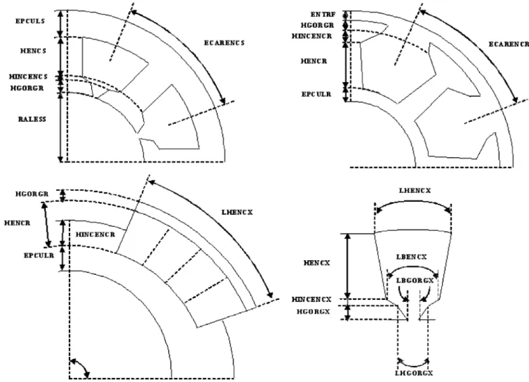
Fig. 1. Geometric (angular and dimensional) data of some stators (slot, tooth, yoke) and rotor (slot, permanent magnet) of different type of different motor types (induction, synchronous, reluctance).
We assume that the meshing tool is capable to mesh quadran-gular regions of any kind: contour lines can be arc of circle or segment of straightline.
We assume that the solver has a standard data base. Inputs are: a table of node coordinates, a table of element location, a table of element material properties, a table informing which winding each element belongs to, a table of nodes with homoge-nous Dirichlet conditions , a table of nodes with odd or even cyclic boundary conditions. Output are: the third compo-nent of vector potential (Az) on each node. The flux is calculated from Az on each node and from the table which relates elements to windings.
B. Requirements
The main requirement of the tool is that it can consider sev-eral types of machines: induction motor, synchronous motor, re-luctance motor. The motors can have several kinds of geometry configuration (the rotor can be outside or inside the stator), sev-eral kinds of structure (the numbers of phases, of pair of poles and slots can vary); several kinds of winding are considered (concentrated or distributed). This tool can consider machines of any dimensions according to the fact that these dimensions are compatible between themselves and with the type of the ma-chines, their configuration and their structure.
C. From Geometric and Material Data to the Geometry
First the data that describe these types of motor must be struc-tured. We have classified them in structural, physical and geo-metric data. These data are loaded from any text editor and read first by the program. The following list gives some examples.
Structural Data:
• Motor type (induction, synchronous, permanent magnet synchronous, reluctance);
• Number of poles;
• Rotor configurations (exterior or interior); • Numbers of phases (stator and rotor); • Numbers of slots per pole and phase; • Windings type and parameters, etc.
Geometric Data (Shown on Fig. 1):
• Internal radius of the stator (RALESS); • Airgap (ENTRF);
• Thickness of the yokes (EPCULX); • Winding height (HENCX);
• Thickness of the slot openings (HINCENCX); • Thickness of the tooth tops (HGORGX);
• Angular width of the slot bottoms, the slot sides opposite to airgap (LHENCX);
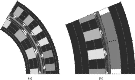
Fig. 2. Drawings of the geometries of some examples of motor types considered: (a) synchronous and (b) permanent magnets synchronous.
Fig. 3. Meshes of the machines of the Fig. 2.
• Angular width of the slot openings (LHGORGX); • Angular width of slots (LBGORGX).
For permanent magnet synchronous motors, some of these pa-rameters have the same name but different meaning..
Physical:
• Materials type and parameters; • Current densities.
The study domain is defined from these parameters. It is di-vided in quadrangular regions characterized by contour lines, a material property and the number of the winding to which it belongs if necessary. Thus all the quadrangular regions are cre-ated. The results obtained for each kind of machines appear on Fig. 2.
D. From Geometry to the Mesh
Then a number of nodes are affected to each line of each region. This affectation is performed automatically according to a simple law that can be described like this: the number of nodes on the lines (arc) in the airgap is equal to twice the number of slots harmonics considered multiplied by the number of slots in the study domain. This simple rule allows to meet any degree of
precision required by applications [1]. The numbers of nodes on other lines are calculated in function of their distance from the airgap. The division of lines performed by our simple law can be seen on Fig. 2.
When all the data structures of each region are filled, the mesh tool (Triangle [5]) is called to mesh each region. During this process the tables affected to each element are filled from the physical characteristics of each region. The elements and nodes of all elements are collected together and then renumbered in order to reduce the bandwidth of the stiffness matrix. The ho-mogenous Dirichlet conditions are assigned automatically to the nodes on the frontier of the study domain located at the min-imum and maxmin-imum radii. Cyclic boundary conditions that can be odd or even are assigned to those located at the minimum and maximum angles of the study domain. The meshes corre-sponding to the machines which appear on Fig. 2 are given on Fig. 3.
E. Computation of Characteristics and Performances
At a design stage, waveforms of the flux and the feeding cur-rents of the electrical machines are assumed to be ideal: rect-angular, trapezoidal or sinusoidal. So the performances or the
Fig. 4. Example of flux density computed by our tool for a permanent magnet motor obtained from a multi-criteria optimization problem.
characteristics of electrical machines can be deduced from flux computations. For instance, for a permanent magnet machine with sinusoidal waveforms, the no-load flux in windings due to magnets and the flux in windings for two types of load currents (longitudinal and transversal) are computed. From these three values, the torque, flux and voltage can be calculated for any type of sinusoidal currents.
F. Verifications
In order to allow the students to verify their results, the tool can be linked to existing FE softwares. This can be performed at different stages with the help of files: drawing files (DXF), pre-mesh files [4] describing the regions, pre-mesh files with or without the potential on each node.
Fig. 4 shows flux density displayed by our own general pur-pose FE software. In order to obtain these results we have only given the sizes of the different parts of the motor and the mate-rial data. Our tool computes automatically the vector potentials on nodes and the flux in windings for any load currents.
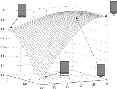
Fig. 5. Evolution of the electromagnetic torque in function of the slot top width and the slot opening.
Such a tool can also be very helpful to study the influence of some parameters. For instance it is possible to study the electro-magnetic torque in function of the slot opening and the slot top width. This kind of computation is extremely difficult to per-form by means of an analytical model. The results are shown on Fig. 5.
IV. CONCLUSION
In this paper, we have discussed about the use of FEM for help to teach applied electrodynamics. We have presented the requirements of a tool adapted to tutorial designs of electrical machines. Guidelines to build such a tool are presented, a pro-totype has been realized and some results have been presented.
ACKNOWLEDGMENT
The work of F. Messine was supported by the ENSEEIHT-IRIT.
REFERENCES
[1] N. Sadowski, Y. Lefévre, M. Lajoie-Mazenc, and J. Cros, “Finite el-ement torque calculation in electrical machines while considering the movement,” IEEE Trans. Magn., vol. 29, no. 2, pp. 1410–1413, Mar. 1992.
[2] C. F. Parker, J. K. Sykulsi, and S. C. Taylor, “Parametric environment for EM computer aided design,” IEEE Trans. Magn., vol. 32, no. 3, pp. 1433–1436, May 1996.
[3] F. Wurtz et al., “Methodological guidelines for the use of analytical and numerical models in a design process of an electromagnetic device,”
IEEE Trans. Magn., vol. 34, no. 5, pp. 3411–3414, Sep. 1998.
[4] C. Henaux, S. Astier, Y. Lefévre, and M. Lajoie-Mazenc, “First steps toward full integrated cad system for electrical machines,” Compel., vol. 14, no. 4, pp. 151–155, 1995.
[5] J. R. Shewchuk. Triangle: Engineering a 2D quality mesh gen-erator and delaunay triangulator. presented at First Workshop on Applied Computational Geometry. [Online]. Available: http://www-2.cs.cmu.edu/quake/triangle.htm