HAL Id: tel-01853140
https://pastel.archives-ouvertes.fr/tel-01853140
Submitted on 2 Aug 2018HAL is a multi-disciplinary open access
archive for the deposit and dissemination of sci-entific research documents, whether they are pub-lished or not. The documents may come from teaching and research institutions in France or abroad, or from public or private research centers.
L’archive ouverte pluridisciplinaire HAL, est destinée au dépôt et à la diffusion de documents scientifiques de niveau recherche, publiés ou non, émanant des établissements d’enseignement et de recherche français ou étrangers, des laboratoires publics ou privés.
Antoine Dricot
To cite this version:
Antoine Dricot. Light-field image and video compression for future immersive applications. Signal and Image processing. Télécom ParisTech, 2017. English. �NNT : 2017ENST0008�. �tel-01853140�
Contents
Abstract 5
Introduction 7
I Context and state-of-the-art 11
1 Principle of current video compression standards 13
1.1 Hybrid video coding scheme . . . 13
1.2 Some improvements of HEVC over H.264/AVC . . . 14
1.3 Multi-view and 3D extensions of HEVC . . . 16
1.3.1 Multi-View plus Depth format (MVD) . . . 16
1.3.2 MV-HEVC - Multi-view extension . . . 16
1.3.3 3D-HEVC - 3D extensions . . . 17
1.4 Performances . . . 18
2 Towards an end-to-end light-field system: current status and limitations 19 2.1 Introduction . . . 19
2.2 Sampling the light-field: capture and formats . . . 20
2.2.1 Definition of the light-field . . . 20
2.2.2 Super Multi-View: convergent and divergent camera arrays . . . 20
2.2.3 Integral imaging: light-field or plenoptic cameras . . . 22
2.2.4 Other light-field formats: Point Clouds and Meshes . . . 23
2.2.5 Similarities, differences, and tradeoffs between formats . . . 24
2.3 Display systems . . . 24
2.3.1 Main light-field displays: projection-based systems . . . 24
2.3.2 Other light-field displays . . . 25
2.4 Processing tools . . . 26
2.4.1 View extraction from integral images . . . 27
2.4.2 Depth map estimation . . . 28
2.4.3 View Synthesis . . . 29
2.5 Light-field content compression based on current encoders . . . 30
2.5.1 Super Multi-View compression . . . 30
2.5.2 Integral images compression . . . 31
2.6 Conclusion . . . 31 1
II Integral imaging 33
3 Integral images compression scheme based on view extraction 35
3.1 Introduction . . . 35
3.2 State-of-the-art . . . 36
3.3 Proposed scheme . . . 37
3.4 Anchor selection and performance evaluation method . . . 38
3.5 Proposed methods with one extracted view . . . 42
3.5.1 Iterative methods to tune the scheme . . . 42
3.5.2 Impact of the position and size of the extracted patch . . . 49
3.6 Improvement of the filtering step . . . 51
3.6.1 Wiener Filter in integral image reconstruction . . . 52
3.6.2 Proposed Wiener filter based methods . . . 52
3.6.3 Experimental results . . . 52
3.7 Proposed methods with several views . . . 54
3.7.1 Experimental conditions . . . 54
3.7.2 Experimental results . . . 55
3.8 Combination and comparison with state-of-the-art methods . . . 56
3.9 Perspectives . . . 59
3.9.1 CU level competition with intra mode . . . 59
3.9.2 View extraction with dense disparity map . . . 59
3.9.3 Display/format scalable feature . . . 61
3.9.4 Other perspectives . . . 61
3.10 Conclusion . . . 62
III Super Multi-View 63 4 Subjective evaluation of super multi-view compressed contents on light-field displays 65 4.1 Introduction . . . 65
4.2 Super Multi-View display system used in our experiments . . . 66
4.2.1 Example of light-field display system . . . 66
4.2.2 Light-field conversion . . . 67
4.3 Preliminary encoding configurations experiments . . . 67
4.3.1 Experimental content . . . 67
4.3.2 Depth estimation . . . 68
4.3.3 View synthesis . . . 68
4.3.4 Group of views (GOV) . . . 69
4.3.5 Inter-view reference pictures structure . . . 71
4.4 Objective experimental results . . . 73
4.5 Subjective evaluation . . . 73
4.5.1 Experimental conditions . . . 73
4.5.2 Subjective results . . . 79
4.5.3 Impact of depth estimation and view synthesis . . . 81
4.5.4 Range of bitrate values for compressed light-field content . . . 82
4.5.5 Comparison between objective and subjective results . . . 83
CONTENTS 3
4.5.7 Comments on motion parallax . . . 87
4.6 Conclusion . . . 87
5 Full parallax super multi-view video coding 91 5.1 Introduction . . . 91
5.2 State-of-the-art . . . 92
5.2.1 Multi-view video coding standards and specific coding tools . . . 92
5.2.2 Improvement for full parallax configuration . . . 92
5.3 Proposed inter-view reference pictures configuration . . . 93
5.3.1 Reference and proposed schemes . . . 93
5.3.2 Experimental results . . . 96
5.4 Adaptation and improvement of inter-view coding tools . . . 97
5.4.1 Merge candidate list improvement . . . 97
5.4.2 Inter-view derivation of the second DV . . . 97
5.4.3 Experimental results . . . 98
5.5 Conclusion . . . 99
6 On the interest of arc specific disparity prediction tools 101 6.1 Motivations . . . 101
6.2 State-of-the-art . . . 101
6.2.1 Anchor results . . . 101
6.2.2 Generalization of 3D-HEVC coding tools . . . 102
6.3 Comparison of coding performances between arc and linear content . . . 102
6.4 Analysis of the content . . . 103
6.4.1 Disparity in arc content . . . 103
6.4.2 Percentage of the total bitrate dedicated to motion/disparity . . . . 104
6.5 Proposed methods and preliminary results . . . 107
6.5.1 Modification of NBDV . . . 109
6.5.2 Modification of AMVP . . . 110
6.6 Conclusion . . . 112
7 Compression scheme for free navigation applications 113 7.1 Introduction . . . 113
7.2 State-of-the-art . . . 114
7.3 Performances comparison with existing encoders in different configurations 116 7.3.1 Tested structures . . . 116
7.3.2 Performance evaluation . . . 117
7.3.3 Experimental conditions . . . 118
7.3.4 Experimental results . . . 118
7.3.5 Results analysis . . . 122
7.4 Conclusion and perspectives . . . 125
8 Conclusion 127 Appendix: Proposed compression scheme for free navigation applications 131 8.1 Proposed coding scheme . . . 131
8.1.1 Coding structure . . . 131
8.1.2 Example with the basic method . . . 131
Abstract
Evolutions in video technologies tend to offer increasingly immersive experiences. How-ever, currently available 3D technologies are still very limited and only provide uncom-fortable and unnatural viewing situations to the users. The next generation of immersive video technologies appears therefore as a major technical challenge, particularly with the promising light-field (LF) approach.
The light-field represents all the light rays (i.e. in all directions) in a scene. New devices for sampling/capturing the light-field of a scene are emerging fast such as camera arrays or plenoptic cameras based on lenticular arrays. Several kinds of display systems target immersive applications like Head Mounted Display and projection-based light-field dis-play systems, and promising target applications already exist. For several years now this light-field representation has been drawing a lot of interest from many companies and institutions, for example in MPEG and JPEG groups.
Light-field contents have specific structures, and use massive amounts of data, that repre-sent a challenge to set up future services. One of the main goals of this work is first to assess which technologies and formats are realistic or promising. The study is done through the scope of image/video compression, as compression efficiency is a key factor for enabling these services on the consumer markets. Secondly, improvements and new coding schemes are proposed to increase compression performance in order to enable efficient light-field content transmission on future networks.
Introduction
Recent evolutions in video technologies tend to provide increasingly immersive experiences to the viewer. On the one hand, Ultra High Definition (UHD), with 4K and 8K resolutions, High Frame Rates (HFR), High Dynamic Range (HDR) and also Wide Color Gamut (WCG) are progressively bringing 2D video towards the limits of the perception of the Human Visual System (HVS). However, on the other hand, currently available 3D video technologies fail to massively reach the consumer market, and are not accepted by users because they are still very limited and do not provide comfortable enough experiences.
Stereoscopic 3D only uses 2 views (one for each eye) and therefore cannot provide motion parallax, i.e. it is not possible for the viewer to change his point of view (for example by moving in front of the screen to gather more information about the scene). This psychological cue that contributes to the perception of depth is however a key element for immersive applications [1]. Moreover, the use of glasses causes discomfort, and the conflict between the accommodation distance (eyes are focused on the screen) and the convergence distance (eyes converge on the image of the object possibly in front of or behind the screen) provides an unnatural viewing situation and is reported to cause headaches and eyestrain (sometimes referred to as cybersickness). Auto-stereoscopic display systems use more than two views (e.g. from 8 to 30) but are still limited by the lack of smooth motion parallax. The viewing positions that allow the users to watch the scene conveniently (i.e. with a correct perception of depth and without artefact) are restricted to certain areas called sweet spots. These unnatural perception stimuli are severe limitations that alter the quality of the visualization and make the viewing experience unrealistic.
The next generation of immersive video technologies appears therefore as a major technical challenge, particularly with the light-field (LF) approach that shows up as one of the most promising candidate solutions. A light-field represents all the light rays in a scene, i.e. rays at every points in space and in every directions, and thus is a function of two angles (ray direction) and three spatial coordinates. This 5-dimensional function is called plenoptic function [2][3]. Conceptually, as 2D video provides a basic sampling of the light-field offering a view of the scene from one angle, light-field acquisition devices provide a wider and denser sampling that offers several views of the scene (i.e. capturing the rays coming from several angles).
For several years now this so-called light-field representation has been drawing a lot of interest from the experts in many companies and institutions. Efforts have been made to assess the potential of the emerging devices and formats, for example by Ad-Hoc Groups in MPEG [4], particularly Free Viewpoint Television (FTV) [5] and Virtual Reality (VR) groups, in JPEG with JPEG Pleno [6], and more recently with a Joint ad hoc group for digital representations of light/sound fields for immersive media applications [7]. New devices have reached the market or are emerging fast. Capture devices are now avail-able like camera arrays (e.g. Google Jump/GoPro Odyssey [8][9], Lytro Immerge [10]) or
plenoptic cameras based on lenticular arrays (e.g. Lytro Illum [10], Raytrix [11]). Sev-eral kinds of display systems target immersive applications like Head Mounted Display (e.g. Samsung Gear VR [12], Oculus Rift [13]) and projection-based LF display systems (e.g. Holografika’s Holovizio [14]). Moreover, appealing and promising target applications already exists (e.g. 360◦ video, already implemented in Youtube [15] and Facebook [16],
that is a first step before 360◦ virtual reality) or are developed (e.g. binocular stereoscopic
360◦, immersive telepresence, free navigation, etc.). Light-field image and video contents
required to create these immersive experiences have specific structures and formats, and use a massive amount of data, that represent a challenge for future transmission on our networks and to set up future services.
The main goal of our work is to study the feasibility of implementing new immer-sive light-field video services. This study is done through the scope of image and video compression, as compression efficiency is a key factor for enabling these services on the consumer and industry markets. We first aim to assess which technologies and formats are realistic and which ones are promising for light-field acquisition, display, and compres-sion considering several target applications. Secondly, we propose improvements of the state-of-the-art compression technologies and new coding schemes in order to increase the compression performance and to enable efficient light-field content transmission on future networks. This manuscript is organized as follows.
◦ Part I is dedicated to the description of the context of our work.
• In Chapter 1, we describe some basic principles of image and video compression that are implemented in current encoders and that are useful to understand the technical work described in this thesis.
• Chapter 2 sets up the context of our work by providing an overview of state-of-the-art light-field technologies from capture to display, including several processes like rendering. This chapter particularly emphasizes on Integral Imaging and Super Multi-View video (SMV) technologies, that are based on microlens arrays and camera arrays respectively, and that are the main focus of our technical contributions. ◦ Part II is focused on our contributions on integral images (or plenoptic images)
compression. This representation provides a dense sampling of the light-field in a narrow angle of view, with a challenging structure for compression.
• Chapter 3 proposes an original integral images compression scheme based on view extraction. It takes advantages of the view extraction process to reconstruct a re-liable predictor and creates a residual integral image that is encoded. We first propose several iterative methods to select the most efficient configuration, using a rate-distortion optimization (RDO) process to avoid exhaustive search methods. Additional runtime savings are then reported by exploring how the different param-eters interact. We assess the impact of the position and size of the patches used for the view extraction on the compression performance. We propose to improve the method with advanced filtering techniques. Methods based on the Wiener filter are used to improve the reconstruction step. The performance of the scheme using sev-eral extracted views is studied. Finally, the behavior of this method in competition or in collaboration with state-of-the-art methods is assessed.
◦ Because integral imaging only captures the light-field under a narrow angle of view, it cannot be used for applications where a large angle of view is required, such as
Introduction 9
Free Navigation for example. Therefore in Part III, we also study the compression of Super Multi-View content, that provides a sparser sampling of the light-field but with a large baseline.
• In Chapter 4, we present a subjective quality evaluation of compressed SMV video content on a light-field display system. While the in-depth understanding of the interactions between video compression and display is of prime interest, evaluating the quality of light-field content is a challenging issue [7]. The main goal of this study is to assess the impact of compression on perceived quality for light-field video content and displays. To the best of our knowledge, the work presented in this chapter is the first to carry out subjective experiments and to report results of this kind.
• Chapter 5 is focused on the compression of full parallax SMV content, e.g. content captured with a 2D camera array (with cameras arranged in horizontal and vertical dimensions). Multi-view encoder extensions are adequate to encode SMV content with horizontal parallax only. Modifications of these encoders have to be applied to encode content with full parallax. We first propose an efficient inter-view pre-diction scheme to exploit horizontal and vertical dimensions at the coding structure level. Then we propose improvements of inter-view coding tools to exploit the two dimensional structure also at the coding unit level.
• Chapter 6 reports results from a study that is focused on the impact of the arc camera arrangements (i.e. instead of typical linear camera arrays) on the compression performance. The performances of existing coding technologies on linear and on arc camera arrangements are first compared. Then we propose perspectives to improve specifically the performance in the arc case (without degrading it for the linear case). • In Chapter 7, we study the compression of SMV content targeting Free Naviga-tion (FN) applicaNaviga-tions. We focus on applicaNaviga-tions where all the views are encoded and sent to the decoder, and the user interactively requests to the decoder a point of view to be displayed (e.g. on a state-of-the-art 2D display). We first compare the performances of state-of-the-art coding methods based on current multi-view encoders. Performance evaluation is based on the tradeoff between compression ef-ficiency (i.e. lowest bitrate possible) and degree of freedom (i.e. the ability for the user to change the viewpoint, that mainly depends on the decoder capability and the number of pictures to decode in order to display one). Additionally, we propose in an appendix chapter a Free Navigation coding scheme that performs redundant encodings, thus allowing the users to shift viewpoint without decoding additional views.
• Conclusions and perspectives are finally drawn in Chapter 8, followed by a list of the publications resulting from the work presented in this manuscript.
Part I
Context and state-of-the-art
Chapter 1
Principle of current video
compression standards
In this chapter we provide an overview of the principles of video compression and also focus on specific tools. The goal is to provide the reader with the description of some fundamental processes that are helpful to understand and appreciate the technical work of our contributions in the next chapters of this manuscript. We first discuss the basic structure of hybrid video encoders like HEVC [17] (High Efficiency Video Coding) and its predecessor H.264/AVC [18] (Advanced Video Coding) by briefly describing the main encoding steps. Secondly we emphasize on specific tools by describing differences and improvements of HEVC against H.264/AVC. Finally, we provide a concise description of the multi-view and 3D extensions of HEVC [19], respectively MV-HEVC and 3D-HEVC.
1.1
Hybrid video coding scheme
Hybrid video coding has been the basis for all video coding standards since ITU-T H.261 in 1989 [21]. HEVC (like its predecessor H.264/AVC) is also based on this concept, which is illustrated in Figure 1.1 [20]. The pictures of the original video sequence are given as input signal to the encoder. A prediction signal is obtained from information that has already been encoded and reconstructed (i.e. available both at encoder and decoder) and is subtracted from the input signal. Resulting prediction errors are represented in the residual, that is transformed, quantized, and encoded into the bitstream. The prediction parameters required at the decoder side to perform the same prediction are also encoded. Blocks included both at encoder and decoder are represented inside the gray box in Fig. 1.1. Input pictures are partitioned into blocks that can be predicted using either intra or inter modes. In intra mode, pixels values in a block are predicted using spatially neighboring pixels (i.e. within the current picture). In inter mode, a block is predicted by a reference block in a temporal reference picture, i.e. with a different Picture Order Count (POC), as illustrated in Figure 1.2. Inter prediction is referred to as motion compensated prediction. The displacement between the predictor block in the reference picture and the current block is interpreted as the motion of this area between the two pictures, and is represented by a Motion Vector (MV). At the encoder, the selection of the best prediction mode is driven by a lagrangian Rate-Distortion Optimization process (RDO) that takes into account the degradation of the reconstructed picture compared to the original one, and the cost required to encode the residual signal and all the prediction information (i.e.
Figure 1.1: Hybrid video coding block diagram [20]
Figure 1.2: Motion compensated prediction
directions for intra mode, motion vectors and reference indexes for inter mode).
1.2
Some improvements of HEVC over H.264/AVC
A first version of the HEVC standard (also known as H.265 and MPEG-H Part 2) has been finalized in January 2013 and published in June 2013, 10 years after its widely used predecessor H.264/AVC. Section 1.1) describes the general scheme of hybrid video encoders. In this section we emphasize on some improvements and particularities of HEVC over H.264/AVC, as a way to describe specific aspects of the encoder with more details.
Performances of HEVC offer a gain of 50% compared to H.264/AVC, i.e. for a given image quality level, the required bitrate is two times smaller on average. This performance comes at the cost of an increase in complexity. In [17], it is mentioned that HEVC’s decoder implementation complexity (using modern processing technology) is not a major burden when compared to H.264/AVC, and that encoder complexity is also manageable. Details on implementation complexity are given in [22]. The improvement is not due to a modification of the encoding structure (see Sec. 1.1), but rather to several changes distributed upon the whole set of coding tools. For example here we can cite first the partitioning of the pictures. As opposed to the traditional macroblock in H.264/AVC
1.2. Some improvements of HEVC over H.264/AVC 15
Figure 1.3: Quad-tree partitioning [17]
Figure 1.4: left) Quad-tree partitioning, right) CUs with same motion parameters [25]
using a fixed array size, the Coding Unit (CU) in HEVC supports variable sizes and is therefore adapted to the content of the picture. Partitioning is also more flexible with CUs, Transform Units (TUs) and Prediction Units (PUs) that are organized in quad-trees (see Fig. 1.3 and Fig 1.4). Some other improvements do not change anything conceptually and are just an increase in precision and complexity that is made possible with the evolution of hardware capacity, i.e. faster processors and larger storage. As in H.264/AVC, the precision of motion estimation goes up to a quarter-sample position (i.e. one fourth pixel) for inter mode, and the filtering for sample interpolation is improved with a eight-tap filter and a seven-tap filter, respectively for the half-sample positions for the quarter-sample positions. The number of prediction directions in intra mode is increased from 8 to 35 sub-modes. Additionally, advanced prediction tools have been added. Advanced Motion Vector Prediction (AMVP) is a tool, derived from the work of Laroche [23][24], that predicts the current MVs from the MVs used to encode neighboring CUs. Similarly, Merge [25] mode allows the current CU to copy prediction parameters (MVs and reference indexes) from temporal or spatial neighbors in a candidate list. The same candidate list is built at the decoder side, and only the index of the candidate selected by the encoder is transmitted to the decoder. This mode is very efficient in zones with homogeneous motion, as illustrated in Fig. 1.4. Other improvements are brought to parallel processing (Tiles, Wavefront, Slices) and also to the structure of the bitstream (in Network Abstraction Layers, NAL) for examples. A complete overview of HEVC is given in [17].
Figure 1.5: Texture image and associated depth map (Poznan Blocks)
1.3
Multi-view and 3D extensions of HEVC
1.3.1 Multi-View plus Depth format (MVD)
Multi-view video content consists of several video sequences representing the same scene, but captured from different points/angles of view by two or more cameras. This kind of content usually targets 3D stereoscopic (2 views) and autostereocopic (around 10 views) display systems that provide a visualization of the scene in relief (although with a lot of limitations as mentioned in our Introduction Chapter). These views present strong corre-lations that can be exploited by dedicated encoders [26][19] (see Sec. 1.3.2 and Sec. 1.3.2). The multi-view format can be extended to Multi-View plus Depth format (MVD), where the content also includes the depth maps associated to the views. In MVD format, the view is also referred to as texture. Depth maps are gray level images that represent the distance of the objects from the camera, as illustrated in Figure 1.5. They can be estimated from textures or captured by dedicated sensors. From textures and depth maps it is possible to synthesize additional intermediate views [27]. It is therefore possible to reduce the total bitrate required to encode multi-view content by encoding only a subset of the views with their associated depth maps. At the decoder side, the views that were skipped (i.e. not encoded) can be synthesized from the decoded textures and decoded depth maps. We provide further detailed descriptions about depth maps and view synthesis in Chapter 2.
1.3.2 MV-HEVC - Multi-view extension
MV-HEVC is the multi-view extension of HEVC dedicated to the encoding of multi-view video content. It is the equivalent of MVC for H.264/AVC. MV-HEVC does not provide specific additional prediction tools, but rather some syntax elements that enable inter-view prediction. Inter-inter-view prediction or disparity compensated prediction, is based on the same algorithm as motion compensated prediction. In practice the main difference
1.3. Multi-view and 3D extensions of HEVC 17
Figure 1.6: Motion and disparity compensated predictions
is the use of a reference picture taken at the same time, i.e. that has the same Picture Order Count (POC) index, but from a different view (instead of a picture from the same view with a different POC for temporal prediction). Vectors are called Disparity Vectors (DV) in that case instead of Motion Vectors (MV). Indeed, in temporal prediction the vector represents the motion of a block, i.e. the displacement of an object between two given time instants (or two pictures). In inter-view prediction, the vector represents the disparity between two blocks, i.e. the change of position of an object in the frame due to the different points of view. This is illustrated in Figure 1.6.
1.3.3 3D-HEVC - 3D extensions
3D-HEVC is dedicated to the encoding of multi-view and 3D content. Its design is mainly oriented towards the MVD format. It provides additional specific coding tools. Some are advanced inter-view prediction tools related to textures, e.g. Neighboring Block Dispar-ity Vector (NBDV) and Inter-View Motion Prediction (IVMP), that are both described in Chapter 5, and Advanced Residual Prediction (ARP), or Illumination Compensation (IC). Inter-component prediction tools can use information from the texture encoding pa-rameters to encode the depth maps, e.g. Quad-Tree Limitation and Predictive Coding (QTL/PC) [28]. Also related to the MVD format, specific depth map coding tools are added, e.g. Intra Wedgelet Mode [19]. And finally, synthesis based coding tools, e.g. View Synthesis Prediction (VSP) [19], takes advantages of the synthesis process from textures and depth maps. 3D-HEVC is optimized for MVD formats but is also more efficient than MV-HEVC for textures only.
1.4
Performances
As illustrated in Figure 1.7, the extensions described in this chapter are built on top of each other. 3D-HEVC includes MV-HEVC syntax elements, and MV-HEVC includes HEVC coding tools. These encoders are currently providing the best performance in terms of compression efficiency compared to other state-of-the-art compression techniques in general. For 2D video, HEVC provides 50% gains over its predecessor H.264/AVC. Although the successor of HEVC is already in preparation, with many new coding tools implemented in the Joint Exploration Test Model [29] (JEM) and providing large gains over HEVC (26% at the time of writing this manuscript), this is still an exploration phase with a large increase in complexity, and the standardization process has not started yet. Anchor results for multi-view and 3D extensions of HEVC are reported in [19]. The results depend on the number of coded views. When two texture views are encoded, MV-HEVC provides around 30% average gains over the simulcast case (i.e. each view is encoded independently with HEVC). This gain is brought up to approximately 70% when taking into account only the enhancement view, i.e. the view that benefits the inter-view prediction, and not the base view that has to be coded with HEVC. This second results is of particular interest in our case, because light-field content can include a large number of views, therefore the expected gains are even larger. Finally 3D-HEVC provides additional 19% gains over MV-HEVC in the cases where three textures and associated depth maps are encoded, with six synthesized views. HEVC based compression is de facto the anchor for light-field content encoding and is used for comparison with the methods that we further propose in this manuscript.
Chapter 2
Towards an end-to-end light-field
system:
current status and limitations
2.1
Introduction
In this section, we provide a wide overview of existing light-field technologies. We address the elements that would compose an end-to-end light-field system from capture to display, and discuss some of the bottlenecks and key factors for its development. The question of the requirements for light-field representations has recently been extensively studied, for example in [30] and [31], and a similar study has been done recently in [7] (although with a larger scope, e.g. including audio), where all the elements numbered in Figure 2.1 are discussed in order to find commonalities between the different available formats and technologies. In Figure 2.1, the blocks Sensor and Sensed data converted correspond to the capture of the light-field from a scene and to its representation in a given format. The Encoder and Decoder blocks are dedicated to the compression of this data, hence to the main focus of the work presented in this manuscript. Finally the Renderer and Presentation system blocks represent the conversion of the decompressed data to a target format that depends on the application, and the corresponding display system.
Figure 2.1: Generic end-to-end light-field workflow [7] (source: L. Chiariglione, MPEG). 19
Figure 2.2: Still light-field capture system (Otoy) based on a single moving camera [32].
2.2
Sampling the light-field: capture and formats
2.2.1 Definition of the light-field
A light-field represents all the light rays in a scene, and thus is a function of two angles (ray direction) and three spatial coordinates. This 5-dimensional function is called plenoptic function [2][3]. Depending on the context, this function can also be used with seven dimensions when the time and wavelength (i.e. color) are taken into account. A light-field representation of a scene can be obtained by sampling and capturing a subset of the rays from different points/angles of view. Several techniques are currently used for this purpose, mostly based on a camera array or a single camera coupled to a microlens array, as described in the following sections. The elements presented in the following of this section relate to the Sensor and Sensed data converted blocks in Fig. 2.1.
2.2.2 Super Multi-View: convergent and divergent camera arrays
A static light-field (i.e. still image of a scene from several angles) can be captured using one single camera moving along and/or around one or several axis, e.g. as demonstrated by Otoy [32] with the system illustrated in Figure 2.2. This method is however limited to still scenes only and is also time consuming. In order to capture a moving scene, it is required that the several angles of view are captured simultaneously.
A first intuitive approach to instantly sample the light-field consists in capturing at a fixed point the light rays coming from all around. This way of acquisition is tightly linked to 360◦viewing applications where the user can change the orientation of the visualization
but not the position. It can basically be done by using a camera with one or two large angle lenses (e.g. fish-eyes). Several acquisition devices are already available like Ricoh Theta [33] or Kodak SP360 [34], shown in Figure 2.3. All the information is captured onto one sensor with this kind of devices, hence the resolution is limited.
It is also possible to increase the resolution of the acquired light-field with several sensors using camera arrays. Many arrangements are possible for camera arrays. Ex-isting setups include 1D (horizontal only) or 2D (horizontal and vertical) linear arrays, convergent or divergent circular arrangements, as well as unstructured arrays. Divergent (or omnidirectional) camera arrays can also provide views from all around (i.e. 360◦),
as illustrated in Figure 2.4. For example GoPro Odissey [9] (based on Google Jump [8]) is an horizontal structure based on 16 GoPro cameras. Lytro Immerge [10] has five lay-ers of similar divergent camera arrays (i.e. an horizontal and vertical structure) and is provided with its own stack of servers for storage and synchronization. Several solutions
2.2. Sampling the light-field: capture and formats 21
Kodak SP360 [34] Ricoh Theta [33]
Figure 2.3: Single or double lens based 360◦ acquisition devices
GoPro Odissey (based on Google Jump) [8][9] Lytro Immerge [10] Figure 2.4: Divergent (omnidirectional) camera arrays
based on the same principle exist such as 360Rize (formerly 360 Heroes) [35], that offers different camera structures with for example coupled cameras for stereoscopy, Samsung Beyond [36], based on 16(+1) cameras, and also JauntVR [37] or Omnicam (HHI) [38]. After the capture, the technical challenge consists in mapping the different views into one image that can be fed to existing virtual reality (VR) viewers and display systems. This operation is called stitching and the goal is to process the views in order to match borders and overlapping regions in a way that makes transitions as smooth and as imperceptible as possible, as illustrated in Figure 2.5. Efficient stitching solutions currently exist such as Video Stitch [39].
A counterpart of this approach is the convergent camera array, where cameras are set around (or in front of) the scene. Fujii Laboratory at Nagoya University has implemented
1D linear 2D linear
Figure 2.6: Fujii Laboratory camera arrays at Nagoya University [40]
several types of camera arrays [40], as shown in Figure 2.6, that have been used to provide SMV content to the community for research purpose [41]. Other companies or institutions have presented examples of camera rigs, for example like Technicolor with 4 × 4 cameras or HHI Fraunhofer. Although they provide a large number of views (e.g. from 80 to 100 for Nagoya University’s arrays) with good resolution (i.e. one camera/sensor per view), SMV convergent camera arrays present obvious technical drawbacks. They are costly and bulky, controlled by stack of servers, and therefore complicated to set-up and to move. Moreover, the camera synchronization, color correction, and storage are operations that increase in complexity when the number of cameras gets larger. Non-professional camera array demonstrations are now spread over the Internet [42] with limited numbers of affordable cameras (e.g. based on 15 GoPro cameras), that provide SMV advantages while possibly limiting the aforementioned drawbacks.
2.2.3 Integral imaging: light-field or plenoptic cameras
Integral imaging, also called plenoptic or holoscopic imaging, is another way of sampling the light-field. This technology is based on plenoptic photography [43]. Integral imaging acquisition uses a lenticular array set in front of a single camera device. This lenticular array is composed of a large number of micro-lenses, that can have a round, hexagonal or square shape, and can be aligned in rectangular grid or in quincunx. The resulting inte-gral image consists of an array of Micro-Images (MIs, sometimes referred to as elemental images) as illustrated in Figure 2.7.
Each micro-lens produces one MI, and each MI contains the light information coming from several angles of view. Integral images can be either orthoscopic or pseudoscopic. In the case of pseudoscopic content, the MIs are flipped horizontally and vertically (as shown in Fig. 2.7, where the darker blue of the sea is above the lighter blue of the sky in the MIs). This characteristic has an impact on the processing of the picture and on the display system requirements (see Sec. 2.3).
In [44], Georgiev and Lumstaine describe the focused plenoptic camera. Traditional plenoptic cameras focus the main lens on the micro-lenses and focus the micro-lenses at infinity. In the focused plenoptic camera the main lens is focused well in front of the lenticular array, which is in turn focused on the image formed inside the camera, so that each micro-lens acts as a relay system of the main lens. This configuration allows a trade-off between spatial and angular information inside each MI (see Sec. 2.4.1).
Examples of plenoptic hand-held cameras exist on the consumer market provided by companies like Lytro [10] and Raytrix [11], as shown in Figure 2.8. Test sets composed
2.2. Sampling the light-field: capture and formats 23
(a) Close-up on Micro-Images,
(b) Rendering of the original scene Figure 2.7: An integral image - Seagull [45]
of integral images have also been made available, e.g. by Todor Georgiev on his website [45] or by the ICME 2016 Grand Challenge on Light-Field image compression [46] that provides images taken with the Lytro Illum camera.
2.2.4 Other light-field formats: Point Clouds and Meshes
As opposed to image-based representations like Integral Imaging and Super Multi-View, the light-field can also be represented with object-based (or geometry-based) methods [7] such as 3D meshes and Point Clouds. 3D meshes [47] are a typical data structure used for Computer Graphics and Computer Generated content. Object structures are represented for example by triangular meshes on which 2D textures are applied.
Point Clouds is another object based representation, that can be used for CG content as well, but can also be captured with dedicated depth cameras (e.g. time-of-flight scanners). A point cloud is a collection of points in 3D space, each holding depth and color information in all directions around the central acquisition position. Each point has 3 coordinates
Lytro Illum [10] Raytrix [11] Figure 2.8: Examples of plenoptic cameras
(x, y, z) and can be thought of as a 2D pixel (x, y) of a photograph that is pushed into the depth (z). A technique called splatting is used to fill the holes in the rendering of Point Clouds. Each point is extended with a rectangular or circular shape, either frontal to the viewing direction or oriented with the surface normal, so that overlaps between adjacent splats hide the holes.
2.2.5 Similarities, differences, and tradeoffs between formats
Image-based (Integral imaging, Super Multi-View) and object-based (Point Clouds, 3D meshes) formats all provide light-field representations because they sample a subset of the light-field of a scene. Conversions from one representation to another are technically possible, e.g. from Point Clouds to depth maps or from an integral image to views of the scene. Because the points emit light rays all around, and because the splatting creates a union of all these rays overall, a correspondence between Point Clouds and light-field is clearly suggested [7]. However, the sampling is done in different ways, implying the following tradeoffs. Point Clouds can theoretically provide the wider sampling as a large number of rays is captured, however holes in between points have to be filled to obtain a view of the scene. Therefore a very large amount of data has to be captured to provide a dense sampling. Integral imaging and Super Multi-View capture images of the scene from several angles of view in a more straightforward way. Using a camera rig allows to obtain a wider baseline (e.g. several meters) than using an holoscopic camera for which the baseline, hence the angle, are limited by the size of the micro-lens array. With holoscopic cameras, the resolution of the viewpoint images is limited because the same sensor is shared between all the captured views, while with a camera rig the full resolution of each camera is used for each view. Finally, holoscopic cameras allow a denser sampling of the light-field, because with a camera rig the distance between each view is limited by the size of the cameras.
2.3
Display systems
2.3.1 Main light-field displays: projection-based systems
In this section we focus on the Renderer and Presentation system blocks in Figure 2.1. Similarly to the variety of formats and representations for light-field content, several kinds
2.3. Display systems 25
of display systems exist based on various technologies. We first cite here the projection-based Super Multi-View displays, often just referred to as light-field displays, as they are the most advanced and spread in the domain. The main examples are the Holovizio displays provided by Holografika [14]. These systems are based on a large number of projection units (e.g. up to 80) and screens with anisotropic properties (i.e. that reflects the light according to the angle of projection). SMV content is taken as input (e.g. 80 views), and converted to another form of representation called light-field slices by a dedicated internal process. The conversion depends on the characteristics of the display system such as the resolution, size, arrangement/positions of the projection units, angle of view, and field of depth. Each projection unit takes a light-field slice as input and projects it onto the screen, that separately reflects parts of the picture in the target direction. As a result, the user perceives the part of the content that represents one point of view of the scene depending on his position. The scene appears therefore displayed in 3 dimensions, with depth going from behind to the forefront of the screen, and the viewer is able to move around the object to take benefits of the motion parallax without wearing glasses or being tracked.
Holovizio systems range from tiny screens dedicated to vehicles (e.g. inside cars) to large cinema-like systems with screens sizing up to 3 × 5 meters, offering a range of various target applications with intermediary sizes in between that are closer to a common TV set configuration. Additionally to the projection of Super Multi-View content, these displays can take as input Computer Generated content in the form of Point Clouds for example, like the output of an OpenGL video games or data from Google Maps, opening another field of interactive applications.
These systems are currently considered as the most advanced of their kind, and al-though they are already available for sale, there are still limitations, as for example visual artefacts that prevent to provide a truly immersive experience, especially for natural con-tent (see Chapter 4). Their usage requires large storage and costly computing processes that are performed by servers (provided as part of the display system when purchased). This aspect makes the whole system bulky and not yet affordable for common users. Therefore they are currently used mostly in universities and laboratories, and not yet ready to reach the living rooms of consumers before several years.
As storage, transmission, and lack of content are the main obstacles to a larger de-velopment, the improvement of compression efficiency and representation for light-field content is a key element to trigger the spread of this technology. The processes related to the conversion and projection steps are described in greater technical details in Chap-ter 4 as the subjective evaluation experiments described in that chapChap-ter were performed in collaboration with Holografika on one of the Holovizio systems.
2.3.2 Other light-field displays
With Super Multi-View, Integral Imaging is the other format that offers interesting per-spectives for light-field representation dedicated to immersive applications. Current ap-plications concern mostly plenoptic photography, with the rendering of one 2D picture of the scene, that can be refocused, and rendered with different angles of view and depths of field. However, other use cases are foreseen involving light-field display systems based on a lenticular array, similarly to the capture device. Several systems have been proposed or mentioned in the literature, as for example by NHK [48]. However, most of these dis-plays are experimental or prototypes. Limitations still have to be overcome in order to
Samsung Gear VR [12] Oculus Rift [13] Figure 2.9: Examples of Head Mounted Displays
make these systems realistic and ready for the users. As integral images can be either orthoscopic or pseudoscopic (i.e. the MIs are flipped horizontally and vertically), display systems should be adapted. Moreover, very large resolutions are required for integral im-ages. Many improvements are proposed in the literature to solve the current limitations of holoscopic display systems like the limited depth of field, limited range of viewing angles, or the conversion from pseudoscopic to orthoscopic images [49][50]. Among all the display systems cited in [48], only integral imaging systems are able to display content with full parallax.
One of the main target display systems for VR applications are Head Mounted Dis-plays (HMD). Examples of HMD are already available on the consumer market, such as Samsung Gear VR [12] or Oculus Rift [13], illustrated in Figure 2.9. Other HMD systems are proposed by major companies (e.g. Google Cardboard, Zeiss, Razer, Intel, Canon, Sony). A connection can be discussed with systems dedicated to Augmented Reality (e.g. Microsoft HoloLens) as these systems can display virtual 3D content that is mixed with the reality perceived through the glasses. The main limitations of HMD systems are: the resolution, as the input content generally consists in extremely large frames as illustrated in Fig. 2.5 (Sec. 2.2); the frame rate, that should target 120 frames per second; the degree of freedom (DoF), with 6 degrees of freedom being the optimal case where the user can change the position and the angle of views across all the axis; and the field of view (FoV), that depends on the target application. Systems like Google Cardboard or Samsung Gear are dedicated to mobile devices and can make use of a smartphone as a screen. Therefore improvements are to come with increased resolutions (e.g. 8K or more) for mobile devices. Another kind of system is presented in [48] and referred to as all-around. These display systems are presented in a table-top configuration, hence they offer a viewing angle of 360 degrees to the user who can walk/turn around the device. Some systems use a rotating mirror and/or a rotating holographic diffuser (e.g. the light-field 3D display developed by USC [51], or Holo Table developed by Holy Mine [52]) while others are based on parallax barrier (SeeLinder developed by Nagoya University [53]).
2.4
Processing tools
In this section, we describe some of the main processing tools that are used for light-field content. First in Sec. 2.4.1, we describe state-of-the-art methods used to extract viewpoint images from integral images. Secondly in Sec. 2.4.2 and Sec. 2.4.3, the depth estimation
2.4. Processing tools 27
Figure 2.10: View extraction process.
Original object Patch too small Patch too large Correct patch size
Figure 2.11: Patch size in view extraction
and view synthesis processes related to the MVD (Multi-View plus Depth) format are discussed.
2.4.1 View extraction from integral images
Several methods to extract viewpoint images (or views) from an integral image are de-scribed in [54]. Most of the methods extract one patch (a square zone of pixels) from each MI, as illustrated in Figure 2.10. This process is based on the characteristics of the focused plenoptic camera [44] for which there are both angular and spatial information within one MI. The angle of view depends on the relative position of the patch within the MI. A basic version of the method consists in using a patch of size 1×1, i.e. one pixel per MI. The size of the patch defines the depth plane in the scene on which the extracted view will be focused: the larger the patch, the closer the focus plane. The objects that are further or closer will present the following artifacts, illustrated in Fig. 2.11. If the patch is too large (i.e. the object is too far), then redundant parts of the object will be represented in several adjacent patches. If the patch is not large enough (i.e. the object is too close), then parts of the object will not be represented (pixelation).
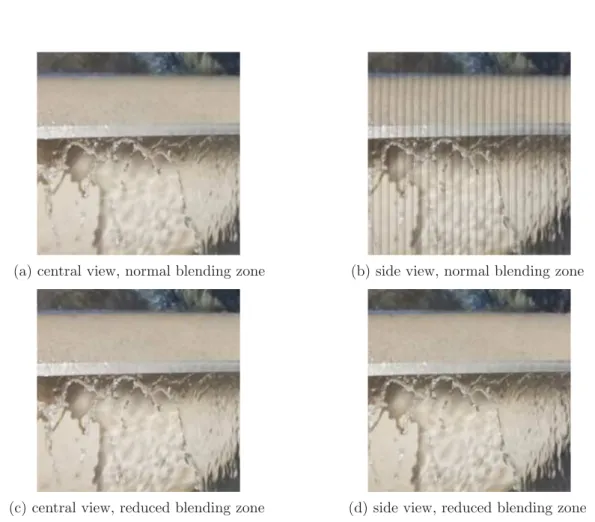
A more advanced method allows reducing block artifacts by smoothing the transitions between adjacent patches. Pixels outside the borders of the patches are blended by a weighted averaging (pixels that are further from the center have a smaller weight, as illustrated in Fig. 2.12). It also blurs the parts of the picture that are out of the depth plane that is in focus (closer or further), which eliminates the above-mentioned mismatch artifacts and provides the same effect as in a common 2D photograph with limited depth of field.
A disparity estimation method is proposed in [44] in order to obtain the relative depth of the objects inside each MI. It is based on a block matching algorithm (illustrated in Fig. 2.13) with the following steps. A square patch P is first selected in the center of the
Integral image
Weight
Position
Extracted viewpoint image
Figure 2.12: Blending in view extraction
P P
k Current MI Right MI
Figure 2.13: Block matching algorithm to estimate disparity between MIs
current MI with coordinates (P x, P y), and a second patch P′ is selected in a neighbor
MI (e.g. right and/or bottom) with coordinates P′x = P x + S + k, with S the size
of the MI and k the disparity between the two MIs. The similitude between P and P′
is computed (e.g. using normalized cross correlation) for values of k from 1 up to the maximum disparity value possible. The value of k providing the maximum similarities between P and P′ corresponds to the disparity value of the current MI. This value in
number of pixels corresponds to the adequate patch size to be used for the view extraction. Viewpoint images resulting from a disparity-assisted patch blending extraction (DAPBe [54]) are full-focused, as each patch size is adapted to the depth of the objects.
2.4.2 Depth map estimation
As mentioned in Chapter 1, the MVD (Multi-View plus Depth) format consists of texture videos, which are actual views of the scene from a given angle, and depth maps, which are gray level images providing information about the depth in the scene (i.e. pixels are darker or brighter depending on the distance from the camera). In case of Computer Generated content, depth maps can be generated automatically from the so-called z information of the 3D structure data. These are therefore ground truth depth maps containing reliable information for each pixel.
For natural scenes, depth maps can be captured using infrared cameras or time-of-flight cameras. A well known example of depth acquisition device is the Kinect [55] camera from Microsoft. Additionally to the gaming application that is its main commercial purpose, it has been widely used in the scientific literature when 3D information is needed in imaging applications for example. The resulting depth images present several limitations. The resolution is generally low and there are many artefacts due to the lack of precision of the cameras, especially on edges. Finally, the range of depth that can be acquired is limited to short distances.
Finally, depth maps can also be estimated from the views. The process to obtain depth values for each pixel in camera coordinates relies on disparity estimation techniques [1].
2.4. Processing tools 29
The principle is to estimate the spatial displacement (in pixels) between two (or more [56]) images that is due to the acquisition from different angles of view.
To resolve this problem, also referred to as stereo-matching problem, several techniques are proposed in the literature, mostly based on two approaches: block-based or pixel-based. Pixel-based algorithms are however preferred in most applications (e.g. encoding and synthesis) because the results are more accurate, around objects discontinuities in the pictures for example. In the pixel-based approach, local methods (i.e. the search is done only in a local window) perform well in textured areas and are convenient for real-time implementations [57][58]. However global methods have also been developed in order to avoid artefacts like noisy disparities in untextured areas and to overcome the issue of occluded areas in the pictures. Disparity estimation techniques are based on epipolar geometry [59]. A mapping between the 3D object points and its 2D projection onto the image plane is done with perspective projection. After an epipolar rectification, that is performed to simplify the problem by assuming a parallel camera arrangements, the search for corresponding points is performed in the resulting epipolar planes.
The Depth Estimation Reference Software [60] (DERS) is the most commonly used tool for compression and coding related applications, when depth maps are required in order to synthesize views that are not encoded. Specific improvements of this software have been recently proposed, for example by Poznan University, in studies of light-field technologies like Super Multi-View in the AHG FTV in MPEG in order to tackle the issues caused by non-linear camera arrays, especially for arc camera arrays [61].
2.4.3 View Synthesis
As mentioned in Chapter 1, it is possible to synthesize intermediate views from textures and depth maps. This technique is particularly useful in coding schemes. Indeed, it is possible to encode only a subset of the views of MVD content with associated depth maps, and to synthesize the views that were skipped at decoder side.
In this process of view synthesis called Depth Image Based Rendering (DIBR), the visual information taken from the available textures is projected or warped into the new position corresponding to the target view to synthesize. The new position (e.g. warping or projection distance) is provided per pixel by the depth information, and hole filling techniques (e.g. like inpainting [62]) are used for disoccluded areas (i.e. areas that are not available in the original texture views). The synthesis can also be improved by taking advantage of the temporal correlations in the intermediate views [63]. In coding applica-tions, the View Synthesis Reference Software [64] (VSRS) is the main tool used for this purpose. Existing tools are efficient for linear camera arrays with horizontal disparity only (although in some cases, artefacts can limit the quality of the synthesized views, as de-scribed in Chapter 4). Like for DERS, specific improvements have been recently proposed in order to tackle the issues caused by non-linear camera arrays, especially for arc camera arrays [61].
2.5
Light-field content compression based on current
en-coders
2.5.1 Super Multi-View compression
Regarding Fig. 2.1, this section details the Encoder and Decoder blocks. Current encoders and their extensions (described in Chapter 1) can be used to encode light-field content [65]. For SMV content, MV-HEVC and 3D-HEVC require only slight syntax modifications [61], e.g. in the number of bits required to encode the view indexes that can be increased. In the first coding configuration considered, all the views are encoded. An example with an MV-HEVC based encoding is illustrated in Figure 2.14. A second configuration is con-sidered where only a subset of the views is encoded as well as the associated depth maps, as illustrated in Figure 2.15. After decoding, the views that were skipped (not encoded) are synthesized (Figure 2.16). Although these coding configurations are technically man-ageable with current technologies, the results are expected to be sub-optimal as current standards do not take into account specific aspects of the light-field content such as the very large number of views (see Chap. 4), the two dimensional camera arrangements in the case of Full Parallax SMV (see Chap. 5), the non-linear camera arrangements like arcs (see Chap. 6), or application requirements like freedom of navigation between points of view (see Chap. 7). Improvements are therefore required. Several methods have been pro-posed in the scientific literature concerning the aforementioned aspects, that are further presented in the state-of-the-art sections of the dedicated chapters of this manuscript.
0 1 N MV-HEVC 0 1 N
Original views Decoded views Encoding /Decoding
Figure 2.14: MV-HEVC encoding scheme (N views)
0 1 E MV-HEVC Original views Decoded depth maps Encoding /Decoding 0 1 E Estimated depth maps 0 1 E 0 1 E Decoded views
Figure 2.15: MV-HEVC encoding scheme (E views + E depth maps)
0 1 E
Renderer Decoded depth
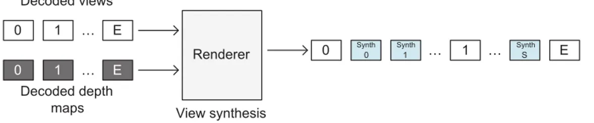
maps View synthesis 0 1 E 0 1 E Decoded views Synth 0 Synth 1 Synth S
2.6. Conclusion 31
2.5.2 Integral images compression
Integral imaging content is represented as a 2D picture and can therefore be encoded using current 2D image and video compression techniques like JPEG or HEVC. Although JPEG has the advantage of being the most used and spread format for still images, coding effi-ciency is much higher with HEVC, as discussed in Chapter 3. Similarly to SMV, encoding integral images with existing technologies is therefore technically manageable, however the large resolutions and the Micro-Images are challenging for common encoders that are not adapted. Several methods for integral imaging compression have been presented in the scientific literature. A detailed review of these methods is provided in the state-of-art section in Chapter 3.
2.6
Conclusion
Target use cases and applications are tightly linked to the significant variety of capture and display devices and to the representation formats. As mentioned in the introduction Chapter, efficient representation of the light-field and efficient compression are key factors to trigger and enable the large development of light-field technologies for future immersive applications. In the following chapters we focus on the compression of Integral Imaging content and Super Multi-View content. We assess the performance with current state-of-the-art technologies and we propose improvements and new innovative schemes adapted to the specific characteristics of these contents.
Part II
Integral imaging
Chapter 3
Integral images compression
scheme based on view extraction
3.1
Introduction
Integral (or plenoptic imaging) provides a dense sampling of the light-field, by capturing a large number of views within a narrow angle (as mentioned in Chapter 2). Plenoptic cameras use lenses to capture light rays coming from several directions. Each micro-lens provides a micro-image (MI) in the resulting integral image. Integral images have a large resolution in order to provide a large number of viewpoint images with a sufficient resolution. Current resolutions are actually not even sufficient, and therefore larger sizes should be expected in the future for this kind of content. Moreover, the micro-images (MIs) based structure (grid-like) involves a large number of edges, which is challenging to encode. New efficient coding technologies are required to handle these characteristics. We propose an original compression scheme to encode integral images. It takes advantages of a view extraction process to reconstruct a reliable predictor and creates a residual integral image that is encoded. Although it offers some kind of display scalability, as a bitstream containing the extracted views is transmitted to the decoder, the first goal of the proposed scheme is compression efficiency.
In section 3.2, state-of-the-art methods to encode integral imaging content are pre-sented. The proposed compression scheme is described in Section 3.3. The anchor and evaluation methods for compression performances are discussed in Section 3.4. In Sec-tion 3.5, we study the performance of the scheme with a single extracted view. As this scheme is highly parameterizable, we first propose several iterative methods to select the most efficient configuration, using a rate-distortion optimization (RDO) process to avoid exhaustive search methods. Additional runtime savings are then reported by exploring how the different parameters interact. In a second time, we assess the impact of the posi-tion and size of the patches used for the view extracposi-tion on the compression performance. In Section 3.6, we propose to improve the method with advanced filtering techniques. Wiener filter based methods are used to filter the view before the reconstruction step. The performance of the scheme using several extracted views is studied in Section 3.7. Finally in Section 3.8, the proposed scheme is combined and compared to relevant state-of-the-art methods. Perspectives and conclusions are drawn in Section 3.9 and Section 3.10 respectively.
3.2
State-of-the-art
In Chapter 2, we mention that encoding integral images with existing technologies is technically manageable, but that common encoders are not adapted to the specific aspect of this content, and expected to be inefficient. Improvements and new coding schemes have been proposed in the scientific literature.
A natural approach consists in applying the Discrete Cosine Transform (DCT) to the micro-images, followed by quantization and lossless coding. A differential coding between MIs can be used [66]. The differential coding can also be used for video sequences in order to remove the temporal correlations [67][68]. Inter-MIs correlation can be removed using the 3D-DCT on stacked MIs. Several scanning orders are tested in order to create the MIs 3D structure. An optimization of the quantization step (for 3D-DCT based compression algorithms) is proposed in [69]. This optimization is done by generating a matrix of quantization coefficients which depends on the content of the image. In [70], an hybrid 4-dimensional transform based on DWT and DCT is described (4D hybrid DWT-DCT coding scheme). The 2D DWT is applied to the MIs, followed by a 2D DCT applied to the resulting blocks of coefficients. In [71], the integral image is decomposed in viewpoint images. A 2D transform is performed by using 1D transforms on the lines and rows of the viewpoint images, resulting in 4 frequency sub-bands. The lower band is a coarse approximation of the original viewpoint image. The 2D transform is applied recursively to increase the level of decomposition at a coarser scale. The sub-bands are then grouped in 8 × 8 × 8 elements volumes and processed by a 3D-DCT. As in the previous methods, the coefficient are then quantized and arithmetically coded. In [72], the transform is combined with a Principal Component Analysis (PCA, also called Karhunen-Loeve Transform or Hotelling Transform). DWT is applied to viewpoint images, and then PCA is applied to the resulting coefficients. Several kinds of DWT filters are proposed (e.g. Dauchechies wavelets). In [73], the SPIHT (Set Partitioning In Hierarchical Trees) method allows to display/transmit progressively the integral image as a quality scalable bitstream. Two algorithms (2D and 3D) are proposed. The first one is a 2D-DWT applied to the integral image and followed by the 2D-SPIHT. The second is based on the creation of a volume of viewpoint images on which a 3D-DWT is applied and followed by 3D-SPIHT.
Another approach consists in encoding the viewpoint images or the MIs of a still in-tegral image as if they were a video sequence (called Pseudo Video Sequence or PVS) and then exploiting the temporal prediction tools of traditional video coders [74][75]. The method proposed in [76] exploits the inter-MIs redundancies (using the optical charac-teristic that MIs have overlapping zones). In [77], a KLT is applied to the viewpoint images. The viewpoint images can be encoded as a multi-view sequence (using inter-view prediction). In [78] and [79], the viewpoint images are encoded using MVC encoder [19]. The exploitation of temporal correlation and inter-view correlations induces an increase in complexity. The Evolutionary Strategy (ES) proposed in [80] is based on the evolution theory and allows an optimization of the coding scheme. In [81], ES is also applied and combined to a half-pixel precision for the motion/disparity estimation and compensation. The Self-Similarity (SS) method exploits the non-local spatial correlation between MIs. The algorithm is mainly the same as for the inter prediction modes (of H.264/AVC [18] and HEVC [17]) but within one frame. A block matching algorithm is used to find a block similar to the current block in the causal zone in the current frame (which corresponds to the blocks that have already been coded and reconstructed). This similar block is then used as a predictor in the same manner as for a temporal prediction. In [82] and [83],
3.3. Proposed scheme 37
the implementation in H.264/AVC of the INTRA SS (for INTRA Self Similarity) modes is described. These publications show the BD-rate gain brought by the SS mode and also the interest of a precise partitioning in macro-blocks. In [84], the SS mode is implemented in HEVC and the interest of the CU partitioning is shown. [85] shows the BD-rate gain brought by this method for video sequences (i.e. with a competition with inter-prediction modes). In [86], a Locally Linear Embedded-based prediction method (LLE) is proposed. The principle is similar to template matching. A search is performed in the causal zone in order to find a predictor block that has the neighboring pixels that match the best with the neighboring pixels of the block to predict. The same search can be performed at the decoder side, so that the amount of prediction information to transmit is reduced.
In [87] a scalable coding scheme is described as follows: the layer 0 corresponds to an extracted view, the layer 1 corresponds to a set of extracted views and the layer 2 is the integral image. Layers 0 and 1 are encoded respectively with reference HEVC and MV-HEVC encoders. For layer 2 the self-similarity method is used. An inter-layer prediction is also proposed, in which a sparse integral image is reconstructed from the set of views of the layer 1 and is inserted in the reference picture buffer to encode layer 2.
In response to the recent ICME 2016 Grand Challenge on Light-Field image com-pression [46], the aforementioned methods (i.e. SS [88][89], LLE [90], PVS [91][92]) have been proposed to overcome JPEG performances on plenoptic image compression. The wavelet-based and 3D-DCT based methods are conceptually far from the hybrid video encoder schemes (H.264/AVC and HEVC) and more adequate for still image coding than for video, whereas the self-similarity and multi-view methods are more easily included in the structure of these reference video encoders. The layered scheme offers an interesting display scalable feature but requires an additional increase in bitrate. In this chapter, we propose a new efficient coding scheme for integral images. As mentioned in Sec. 3.1, although it provides some level of display scalability, it targets compression efficiency. Additionally, this scheme is not restricted to still images.
3.3
Proposed scheme
In this section, the proposed compression scheme (Figure 3.1 and Figure 3.2) is described. In this scheme, a residual integral image IIR is encoded with HEVC. This corresponds to
the residual stream in Figure 3.1. IIR is the difference between the original image II and
a reconstructed image II∗. II∗ is reconstructed from viewpoint images extracted from the
original integral image II. Extracted views are encoded with 3D-HEVC. This is the views stream in Figure 3.1. The number of views is not limited. Due to their small resolution, views represent a small number of bits to encode compared to II. Moreover, they have a natural image aspect that is less costly to encode than the MI based structure of II. To obtain views with such a smooth aspect, advanced extraction methods are used, which use blending and varying size patches (see Chapter 2), both however preventing from perfect reconstruction with the exact original pixel values. The corresponding missing information, the difference between II and II∗, is recovered in II
R. By definition, for
a reconstructed image II∗ close to the original II, the subtraction is expected to provide
absolute values close to zero. Therefore, under this condition, IIRhas a flat aspect with low
variations, which is easier to encode with HEVC than II. In practice, IIR can have a noisy
aspect because of reconstruction errors, as discussed and illustrated in Section 3.5.1.4. During the reconstruction performed in this scheme, the patches in the viewpoint image(s) are copied to their original position within the MIs in the reconstructed image
![Figure 2.6: Fujii Laboratory camera arrays at Nagoya University [40]](https://thumb-eu.123doks.com/thumbv2/123doknet/2791728.65785/25.892.164.690.201.394/figure-fujii-laboratory-camera-arrays-nagoya-university.webp)