HAL Id: tel-03167632
https://pastel.archives-ouvertes.fr/tel-03167632
Submitted on 12 Mar 2021
HAL is a multi-disciplinary open access archive for the deposit and dissemination of sci-entific research documents, whether they are pub-lished or not. The documents may come from teaching and research institutions in France or abroad, or from public or private research centers.
L’archive ouverte pluridisciplinaire HAL, est destinée au dépôt et à la diffusion de documents scientifiques de niveau recherche, publiés ou non, émanant des établissements d’enseignement et de recherche français ou étrangers, des laboratoires publics ou privés.
Bedload fill of abandoned channels
Leo Szewczyk
To cite this version:
Leo Szewczyk. Bedload fill of abandoned channels. Environmental Engineering. Université Paris sciences et lettres, 2020. English. �NNT : 2020UPSLM056�. �tel-03167632�
Préparée à MINES ParisTech
Bedload fill of abandoned channels
Remplissage de chenaux abandonnés par la charge de
fond
Soutenue parLéo SZEWCZYK
Le 18 Décembre 2020 Ecole doctorale n° 398Géosciences, Ressources
Naturelles et Environnement
SpécialitéGéosciences et
géo-ingénierie
Composition du jury : Christian, GORINIProfesseur, Sorbonne Université Président du jury
Gilles, ARNAUD-FASSETTA
Professeur, Université de Paris Rapporteur
Frédéric, CHRISTOPHOUL
Professeur, Université Paul Sabatier Rapporteur
Philippe, CLAUDIN
Directeur de Recherche, ESPCI Paris Examinateur
François, METIVIER
Professeur, IPGP Examinateur
Michal, TAL
Maitre de Conférences, CEREGE Examinateur
Isabelle, COJAN
Directeur de recherche, MINES ParisTech Directeur de thèse
Jean-Louis, GRIMAUD
i
Abstract
This PhD is a contribution to the understanding of bedload sediment deposition in abandoned channels. Experimental and field investigations were combined to link hydrology and geomorphic evolution, and to propose an architectural model for bedload fills.
Experiments conducted using a fixed-bank and bed flume under constant sediment and water supply showed identical deposition processes under varied channel geometry, which occurred in two phases for channel plug formation. Sedimentation initiated downstream of the bifurcation in a flow separation zone whose size increased with the diversion angle. Channel plug then formed and thickened through the amalgamation of bars. In free flow conditions, i.e., without perturbation of the water surface slope, channel plug length and volume are controlled by the channel diversion angle. When the water-surface slope is modified in the disconnecting channel, channel plug geometry may be better predicted using the water surface slope –or length- ratio between the two channels.
Field surveys conducted in channels in both open- and closed-stages allowed comparisons with the experimental results. The morphologies of the channel plug deposits are similar in natural cases to the one observed in flume experiments, suggesting comparable deposition processes. Field observations in disconnecting channels allowed enriching the architectural model by integrating lateral accretion deposits occurring in early stages of abandonment, and characterizing fining-upwards and downstream trends of bedload deposits. Observations in channels abandoned for centuries showed that coarse-grained fill deposits architecture can be preserved through time provided that no reactivation of the channel occurred.
Finally, an experimental relationship linking the channels length ratio and plug length tested with field data appeared reliable to estimate a minimum channel plug length, and suggested that the remaining plug length consists of heterolithic deposits.
iii
Résumé
Cette thèse contribue à la compréhension des processus de dépôts des sédiments grossiers dans les chenaux abandonnés. La combinaison d’études expérimentales et de terrain a permis de lier hydrologie et évolution géomorphologique des remplissages formés par la charge de fond, et de proposer un modèle de leur architecture.
Des expériences réalisées grâce à un modèle analogique au lit et bancs fixes auquel était fourni un apport constant d’eau et de sédiment ont montré que les sédiments sont déposés par des processus identiques indépendamment de la géométrie du chenal. Le bouchon de chenal se forme en deux phases. La sédimentation est initiée dans une zone de séparation du courant dont la largeur augmente avec l’angle de diversion. La formation et l’amalgamation de barres poursuit ensuite l’extension et l’épaississement du bouchon de chenal. En écoulement libre, c'est-à-dire sans perturbation de la surface libre de l’eau, la longueur et le volume du bouchon de chenal sont contrôlés par l’angle de diversion. Quand la surface libre est modifiée dans le chenal en cours de déconnexion, la géométrie du bouchon de chenal est contrôlée par le ratio entre les surfaces libres, ou les longueurs, des deux chenaux.
Des études de terrain effectuées dans des chenaux aux stages ouverts et fermés de la déconnexion ont permis de comparer observations naturelles et résultats expérimentaux. La morphologie du bouchon de chenal est similaire dans les deux cas, suggérant des processus de dépôts comparables. Les études de terrain réalisées dans des chenaux en cours de déconnexion ont permis d’enrichir le modèle architectural en intégrant des dépôts formés par accrétion latérale déposés lors de la phase initiale de déconnexion, et d’observer une tendance grano-décroissante normale et vers l’aval des dépôts de charge de fond. Des observations dans des chenaux abandonnés depuis plusieurs siècles ont montré que les dépôts de remplissage grossiers peuvent être préservés dans le temps, tant que le chenal n’est pas réactivé.
Finalement, une relation expérimentale liant le ratio de longueur entre les chenaux et la longueur du bouchon de chenal a été testée sur des données de terrain. Elle parait fiable pour estimer la longueur minimale du bouchon de chenal, et suggère que le reste de la longueur du bouchon est formée par des dépôts hétérolithiques.
v
Acknowledgments
First and foremost I would like to thanks my supervisors Jean-Louis Grimaud and Isabelle
Cojan for their support, guidance and trust. I have learned a great deal thanks to you during
these three years.
I would also like to thank the members of my jury, the rapporteurs Gilles Arnaud-Fassetta and Frédéric Christophoul, and the examiners Philippe Claudin, Christian Gorini, François
Métivier and Michal Tal, for accepting to read and evaluate my work.
I am thankful to Hervé Piégay for his help in selecting study sites and his input both on the field and during the later reflexion I am indebted to Aurélien Baudin, Cyril Leipp, Yasmina
Habaoui, David Marquez for their help in building the experimental flume used during this
PhD, and to Loïc Marlot for his invaluable help during the field surveys. I am also grateful to
Armand Crouzet and Pierre Maria for conducting some of the experiments used in this
dissertation. Likewise, I am grateful to Christine Franke for her financial support that allowed us to buy the sediment feeder for the flume experiments and fund radiocarbon dating. I am also grateful to Laurent de Windt and Alexandrine Gesret for their help with the doctoral school covid situation. Finally, this journey would not have been possible without the discreet yet relentless and essential work of Sylvie Boj and Véronique Lachasse, who made sure that every administrative task went smoothly.
These years have also been a formidable human experience. I consider myself extremely lucky to have done my PhD at the Centre de Géosciences where I have met truly wonderful people. Alas, three years is far too short a time to live among such excellent and admirable persons. I am thinking first of the people that put up with my lame jokes at the morning tea far too often, Caroline, Christine and Damien and his map but also to those who left before the end (totally unrelated to my sense of humour): Martin, Kiki, Thomas and Saro. A few special thanks are in order. Thanks Loïc for being the delicate, refined and elegant creature that you are, and a totally, totally, trustworthy fellow werewolf. Also thanks for feeding me during my quarantine. Alexandre (and your boar), thank you for all the boar- and shoulder-related laughs, and for being an equally trustworthy adventurer that would never, ever, purposely anger a dragon I’m negotiating with. Be wary of saucisson. Bob, you are an amazing and patient story teller who let me be a lizard. It was lovely to share apartments in the mountains with you and to see you put on skis. Nicolas, thank you for feeding me cheese while I was at
vi
my lowest, at my best, and generally speaking when I was hungry. Also thanks for your grace in accepting your national team humiliating and oh so painful and very public defeat and allowing me to gloat. Laure, if I ever need someone to accompany me in the forbidden crossing of a dangerous and dark tunnel, I’ll choose you. Manon, thanks for the honey and medicines I somehow always need and you somehow always have. Marine, I can now confess that I sometimes enjoyed the vegetables you brought. Aurélien, I saw you sip that champagne glass. Jean, I wouldn’t have wanted to put my finger in the DopaMines affair with anyone else, but maybe it is time to let go? Léa, I loved that you managed to be consistently disappointed by the subtlety of my jokes. Audrey, thanks for your family stories, they are always surprising. Anaïs, I will see Anès some day. Anaïs, it was a pleasure to endure your toothpick attacks.
More widely, I am grateful to the PhD students and postdocs (and even a few “non-precarious” persons) for the atmosphere and feeling of comradery that I felt, whether it was at lunch for the tarot breaks, during the board games nights or week end activities or on the ski slopes. I don’t know half of you as well as I should like, and I like less than half of you half as well as you deserve.
The aforementioned persons fed my soul with the warmth of friendship, but alas the flesh is weak and also has needs. I would have failed long ago if not for the delicious and totally balanced diet I followed. I owe Pablo and Alicia at least five kilos, but it was worth it. Huge thanks to Chiara and Lele for the icy desserts (and sometimes afternoon and week end breaks).
A special thought for some special persons. Morgane, well, for being you and always supportive when I need to complain. Maxime, for being such a good gaming partner, even though we are terrible. Margaux, for the 8 years I have known you. It might have been different had we not have been partnered since year one. Hadrien, I still don’t always understand you, but I love the red beard. Eudes, thanks for always letting me lean on you when necessary. These past years I could not see you bunch as much as I wanted to, despite the constant promises. I hope I will do better now.
Finally, I would not have succeeded without my family. I am grateful to my parents, Christine and Kléber, for always, always supporting me and gently pushing me to accomplish my best. You encouraged my curiosity since as long as I can remember, and always gave me the means to satiate it. Martin, big brother, as much as I hated to admit it at times, you have always been
vii
a model for me. Juliette and Salomé, you made him better and the family is greater with you in it. Last but definitely not least, Lisanne, you fully supported me and endured my moods during this adventure. This would have been harder without you. Ik heb nu iets om naar uit te
kijken. I love you all very much.
Reading back this rant, I realise once again how good these PhD years were and the sheer number of amazing people I know. Dear reader, if you do not know any of these persons, but are still reading, first I am impressed at your persistence, and second, worry not, this is the end and the actual stuff you came to read follows.
ix
Contents
Abstract ... i Résumé ... iii Acknowledgments ... v Contents ... ixList of Figures ... xiii
List of Tables ... xviii
Introduction ... 1
Chapter 1: Channel abandonment and infilling – Literature review ... 5
1.1. Introduction ... 6
1.2. Fluvial systems ... 6
1.3. Floodplain dynamics and resulting sedimentary facies ... 10
1.3.1. Channel migration deposits and associated facies ... 11
1.3.1. Overbank deposits and associated facies ... 13
1.3.3. Relation to abandoned channels ... 14
1.4. Channel abandonment processes ... 15
1.4.1. Avulsions ... 15
1.4.1.1. Avulsion types ... 15
1.4.1.2. Avulsion initiation ... 16
1.4.1.3. Avulsion styles ... 17
1.4.2. Chute cutoffs ... 19
1.5. Current models for abandoned channels fill ... 25
1.5.1. Channel fill nature and geometry... 25
1.5.2. Current knowledge on processes controlling channel infilling ... 30
1.5.2.1. Regional controls on channel abandonment and fill ... 30
1.5.2.2. Bifurcation dynamics and its control on disconnection ... 33
1.5.2.3. Closed-stage channel filling processes... 40
1.6. Conclusion ... 42
Chapter 2: Bedload dynamics and deposition in abandoned channels using an experimental bifurcation setup ... 45
2.1. Experimental evidences for bifurcation angles control on abandoned channel fill geometry ... 46
2.1.1. Abstract ... 46
2.1.2. Introduction ... 46
2.1.3. Methods ... 48
2.1.3.1. Experimental design... 48
2.1.3.2. Data acquisition ... 51
2.1.3.3. Sediment transport law ... 52
2.1.4. Results ... 53
2.1.4.1. Bifurcation geometries allowing channel disconnection ... 53
2.1.4.2. Sand plug formation dynamics and architecture ... 57
2.1.4.3. Controls on sand plug length and volume ... 58
2.1.5. Discussion ... 60
2.1.5.1. Bifurcation angle control on abandonment ... 60
2.1.5.2. Bifurcation angle control on sand plug extent ... 61
2.1.5.3. Mechanism for channel abandonment ... 62
2.4.5.4. Comparison with field cases and upscaling ... 63
2.1.5.5. Sand plug architecture integration to reservoir modelling ... 65
2.1.6 Conclusion ... 67
x
2.2.1. Erodible sand bed ... 68
2.2.2. Differential base level and associated backwater dynamics ... 71
2.2.2.1. Experimental design... 71
2.2.2.2. Results ... 73
2.2.3. Interpretation ... 79
2.3. Conclusion ... 81
Chapter 3: Experimental abandonments in curved channels geometries: insights on the architecture of cutoff bedload fills ... 83 3.1. Introduction ... 84 3.2. Methodology ... 86 3.2.1. Experimental design ... 86 3.2.2. Data acquisition ... 90 3.3. Results ... 93
3.3.1. Bedload deposits in the case of local avulsions ... 93
3.3.2. Effects of cutoff channel width on bifurcation (un)stability ... 96
3.3.3. Bedload deposits in the case of cutoff incision ... 97
3.3.4. Controls on channel fill architecture ... 104
3.4. Discussion ... 107
3.4.1. Geometrical controls on channel equilibrium ... 107
3.4.2. Deposition process and architectural elements of abandoned channel fills ... 109
3.4.3. Controls on bedload fill deposits geometry and volume ... 111
3.1.4. Experimental predictive model for channel plug length and volume ... 114
3.5. Conclusion ... 118
Chapter 4: Gravel fill dynamics and depositional patterns in chute cutoffs channels of a bedload dominated river: the Ain River, France ... 121
4.1. Abstract ... 122 4.2. Introduction ... 122 4.3. Study area ... 125 4.3.1. Geomorphic setting ... 125 4.3.2. Studied channels ... 126 4.4. Methods ... 130
4.4.1. Channel fill sedimentary bodies mapping ... 130
4.4.1.1. DEM ... 130
4.4.1.2. Aerial pictures analysis ... 130
4.4.1.3. Observations and data collection on the field ... 131
4.4.2. Estimation of the bedload deposits in the abandoned channel ... 132
4.5. Results ... 135
4.5.1. Channel facies description and interpretation ... 135
4.5.2. Channel fill architecture in the studied channels ... 138
4.5.2.1. Open-stage channel: the CHA site ... 138
4.5.2.1. Closed-stage channels ... 144
4.5.3. Geometrical controls on planar geometry and volume of channel fills ... 147
4.6. Discussion ... 149
4.6.1. Depositional processes of the bedload fill ... 149
4.6.2. Grain-size changes associated with plug formation ... 152
4.6.3. Geometry, extent and volumes of channel plugs ... 153
4.6.4. Cutoffs initiation and bifurcations stability ... 156
4.7. Conclusion ... 157
Chapter 5: Long-term preservation of coarse-grained fill deposits: tests on field observations ... 159
xi
5.2. Reconstruction of a pluri-centenal abandoned channel fill architecture: the Vimpelles avulsion
channel (Seine, France). ... 162
5.2.1. Geographical and geological contexts ... 162
5.2.2. Methods ... 165
5.2.3. Channel fill present architecture ... 167
5.2.4. Coarse-grained fill deposits long-term preservation ... 169
5.2.4.1. Evidences of several phases of activity ... 169
5.2.4.2. Recent moderate-energy reworking events ... 170
5.3. Coarse-grained fill deposits preservation in several systems ... 173
5.3.1. Studied abandoned channels ... 173
5.3.1.1. The Boire Torse channel ... 174
5.3.1.2. The Rijnstrangen channel ... 176
5.3.2. Results and discussion ... 178
5.4. Cutoff channel plug length prediction using aerial pictures ... 180
5.4.1. Study area ... 180
5.4.2. Channel selection and measurement method ... 180
5.4.2.1. Data source ... 180
5.4.2.2. Channel selection ... 182
5.4.2.3. Measurement method and uncertainties ... 183
5.4.3. Results and discussion ... 185
5.5. Conclusion ... 190
Chapter 6: Conclusion and perspectives ... 193
6.1. Main contributions of the PhD ... 193
6.1.1. Experimental results ... 193
6.1.2. Comparison with field examples ... 194
6.2. Future work and perspectives ... 195
6.2.1. Experimental setup improvement ... 195
6.2.2. Complexification of the flume experiments ... 196
6.2.3. Transitional phase and heterolithic deposits study ... 197
6.2.4. Channel fill under tidal influence ... 198
References ... 201
Appendix A: Supplementary material for Section 2.2 ... 215
Appendix B: Supplementary material for Chapter 4 – Ain River channels aerial pictures ... 221
Appendix C: Supplementary material for Chapter 4 – Allier River channels aerial pictures ... 227
xiii
List of Figures
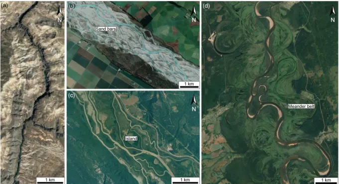
Figure 1.1: Satellite images of the four major types of fluvial systems. (a) Straight river (Gunnison River, USA). (b) Braided river (Rakaia River, South Island, New Zealand). (c) Anastomosed river (Columbia River, Canada). (d) Meandering river (Tchoulym River, Russia). Source: Google Earth Pro. 7
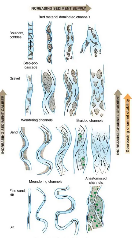
Figure 1.2: Diagram showing the variety of morphologies taken by rivers between the dominant types when the
control factors vary. The main channel types are located at the appropriate positions within the diagram. Shading is intended to reflect sediment character. From Church (2006). 9
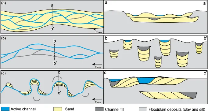
Figure 1.3: Representation of the typical planform and vertical geometry of the deposits formed by three major
types of fluvial systems in aggrading setting. (a) Braided rivers. Low lateral mobility. (b) Anastomosed river. Lateral migration and avulsions. (c) Meandering river. Lateral migration. From Jerolmack & Mohrig (2007). 10
Figure 1.4: One example of floodplain cross section using a Flumy simulation (Lopez et al. 2008) that shows the
spatial relationships between the abandoned channels and other lithofacies in a fluvial meandering reservoir. 11
Figure 1.5: Architecture, grainsize evolution and heterogeneities across a point bar. (a) Typical depositional
sequence of meandering channel deposits (from Donselaar & Overeem 2008). (b) Internal architecture of a point bar displaying internal facies heterogeneities (from Deschamps et al. 2012). 13
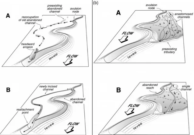
Figure 1.6: Avulsion types. From Stouthamer (2000), Slingerland & Smith (2004) and Bernal et al. (2012). 16 Figure 1.7: Models for avulsions by incision (a) and progradation (b). Both panels show partial reoccupation of
either an old abandoned channel (a) or an active tributary (b). From Mohrig et al. (2000). 18
Figure 1.8: Cutoff mechanisms and geometries. (a) Headward erosion. (b) Embayment incision. (c) Scroll
slough. (d) Neck formation. (e) Mid-channel bar formation. Adapted from Grenfell (2012). Proportions were taken from Lewis & Lewin (1983) after a study of 145 cutoffs in gravel bed rivers of Wales. The missing 18 percents are multi-loop (13%) and artificial cutoffs (5%). 20
Figure 1.9: Satellite images showing chute cutoff initiation and evolution on the Ucayali River, Peru. Chute is
initiated by incision of part of the point bar between two abandoned channels (1996) (1&2), leading to their widening (1997) (3). They become dominant by 2000 and the disconnected channel narrows quickly and a sand
plug forms on its upstream part (4). 23
Figure 1.10: Cutoff formation processes. (a) Embayment formation on a meander bend of the Missouri River,
USA. (b) Flooded swales in the Amazonian floodplain. Pictures from Constantine et al., 2010b. 22
Figure 1.11: Sketch and pictures of headward erosion processes (Powder River, Montana, USA). (a) Schematic
representation of the meander bend in 1985. (b) Isometric drawing of the gully. (c-d) Pictures of the gully facing upstream (c) and downstream (d). Adapted from Gay et al., 1998. 21
Figure 1.12: Satellite images showing neck cutoff initiation and evolution on the Ucayali River, Peru. The
upstream arm of the bend migrates northward (1985-2014) until it joins the downstream arm of the bend,
disconnecting the apex of the meander bend (2015). 24
Figure 1.13: Conceptual sketch illustrating the abandoned channel shape after disconnection (a) and channel
plug architecture immediately after disconnection (b) and after the active channel migration (c). After Rowland
et al., (2005) Not to scale. 26
Figure 1.14: Channel fill deposits model for cross-sections along a channel bend. Arrows show the relative
orientations of the active channel and bars. Bridge et al. (1986). 27
Figure 1.15: Example of detailed architecture analysis in an abandoned channel fill in a Rhine River cutoff
(Netherlands). a: laminated clays. b: clayey silts. c: silts. d: silty sands (Toonen et al., 2012). Based on their observations the authors proposed that the channel fill grainsize evolution translates a global decrease in energy in the abandoned channel, with some flood-related coarser deposits intertwined in the fill. 28
xiv
Figure 1.16: Conceptual sketches displaying the geometry and lithology of the channel fill depending on the
disconnection type. (a) Avulsion. (b) Chute cutoff. (c) Neck cutoff. After Toonen et al. (2012) and Dieras
(2013). 29
Figure 1.17: Illustrative sketch of backwater effects on channel water-surface elevation. x>L: Normal flow.
0<x<L: transitional region. x<0: offshore river plume. hs: water depth at the shoreline. hn: normal flow depth.
Adapted from Lamb et al. (2012). 31
Figure 1.18: Diagram representing the scales, interactions and effects of the controls on bifurcation formation.
31
Figure 1.19: Sketch of a bifurcation highlighting the geometric and hydraulic factors controlling bifurcation
stability. 34
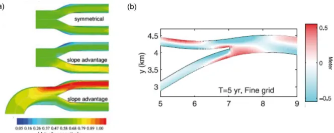
Figure 1.20: Effect of the upstream slope advantage and curvature on flow (a) and sediment erosion or
deposition (b). From Kleinhans et al., 2008 & 2013. 36
Figure 1.21: Sketch illustrating the relationship between length and slope ratios in cutoff cases that allows slope
ratio measurement without having access to elevation data. 37
Figure 1.22: Effects of the diversion angle on the flow separation zone. Flow velocity modeling for a 60°
bifurcation. μ: fraction of the total abandoned channel width occupied by the downstream flow cross-section. ε: flow separation zone (a). Relationship between the diversion angle value and the flow separation zone width (b).
(a-b) from Constantine et al. (2010b). Relationship between the diversion angle value and the flow separation
zone length and width at the upstream and downstream entrances of a water intake. Lu: length upstream. Ld: length downstream. Wu: width upstream. Wd: width downstream. From Keshavarzi & Habibi (2005) (c). 39
Figure 1.23: Diagram representing the local and geometric factors controlling bifurcation stability and their
interactions. 40
Figure 1.24: Channel fill deposits as described by Allen (1965) after the works of Fisk (1947) and Schumm
(1960) (a) and representation of a channel fill cross-section filled by clays as commonly described, as pointed out by Donselaar & Overeem (2008) (b). Allen (1965) and Donselaar & Overeem (2008). 42
Figure 2.1: 3-D sketch showing the occurrences of deposits associated with abandoned channels in an alluvial
plain. 47
Figure 2.2: Overhead view of the experimental setup together with the different angles considered and the levee
breach setup. 49
Figure 2.3: Evolution of the experiments. (a-c) Overhead pictures of the setup for the symmetrical (a) and
asymmetrical configurations without (b) and with levee breach (c). (d-f) Evolution of water discharge measurement at the output of the distributary channels for symmetrical (d-e) and asymmetrical (f-g) configurations. (g) Asymmetrical 90° configurations with varying slope ratios S2/S1. 50
Figure 2.4: Planar growth of sand plug from overhead pictures. (a) Consecutive growth phases of the sand plug
for β2 = 30°. (b) Final states of the sand lug for different β2 angles. Contours are drawn every 15 min. The mean sand plug length is represented with a black circle, together with uncertainties. 54
Figure 2.5: Final topography of Experiment 5 showing the active (1) and disconnected (2) channels. (a)
Elevation DEM. (b) Shaded relief of the same DEM. Contour lines represent 1.5 mm elevation. 55
Figure 2.6: Mean longitudinal elevation profiles of the sand plugs for increasing β2 angles without (a) and with
levee breach (b). Profiles were corrected for bottom slope to facilitate comparisons. The grey area corresponds to the active channel. Empty triangles correspond to the furthest location where the sand plug occupies the entire channel width, while full triangles indicate the subaqueous extremity of the sand plug. 56
Figure 2.7: Relationships between the sand plug length and volume, and the incidence angle β2 (a, b) and slope
ratio S2/S1 for β2 = 90° (c). The regression line for total sediment in panel (b) was not calculated since only
xv
Figure 2.8: Transport law. Volumetric flux per unit width, as a function of Shield parameter θ. The dashed line
corresponds to Eq. (1) fitted to the data (a). Regime relationship between dimensionless discharge Q* and slope measured in the experiments. The solid blue line corresponds to the threshold theory (Eq. 2, θt = 0.17 and Cf = 0.06). The shaded area and dashed lines indicate uncertainty based on varying friction coefficient Cf value (b).
64
Figure 2.9: Conceptual architecture of sand plug derived from experimental observations: overhead view (a),
longitudinal profile (b) and transverse sections (c). 66
Figure 2.10: Final interpreted overhead pictures of the fixed-bed experiments (a, b) and of the sand bed
experiments (a’, b’). 69
Figure 2.11: Mean longitudinal elevation profiles of the sand deposits for the sand bed (Exp. 20, 21) and
fixed-bed (Exp. 7, 9) experiments. The grey area corresponds to the active channel. Triangles indicate the length of the
sand plug in asymmetrical experiments cases. 71
Figure 2.12: Plan view of final states of sand plugs for Exps. 9 (a) and 21 (b). Growth stages are indicated by
the colors. 71
Figure 2.13: Plan view of final states of sand plugs for different β2 angles with a base level of 0 cm (a) and with
a base level rise of 0.5 cm (b). Growth stages are indicated by the colours. 74
Figure 2.14: Mean longitudinal elevation profiles of the sand plugs for increasing β2 angles in no-forcing (a) a
base level elevation of 0.5 cm (b) and a base level elevation of 1 cm (c) scenarios for low diversion angles (15 to 22.5°), symmetrical or slightly asymmetrical experiments. Profiles were corrected for bottom slope to facilitate comparison. The grey area corresponds to the active channel. 75
Figure 2.15: Comparison between mean longitudinal elevation profiles of the sand plugs for increasing β2
angles in no-forcing (a) and base level elevated by 0.5 cm (b) scenarios. Profiles were corrected for bottom slope to facilitate comparison. The grey area corresponds to the active channel. 76
Figure 2.16: Plots of sand plug length (a) and volume (b) and the incidence angle β2 for highly asymmetrical
bifurcations. 77
Figure 2.17: Plot of sand plug length on free flow zone length. Dashed point indicates that backwater zone
length was calculated as the mean of distributary 2 and the inlet channel slope as distributary 2 was flat. 78
Figure 2.18: Plot of disconnection time and base level elevation. 78
Figure 3.1: Overhead view of the experimental setup showing the open- (a) and closed- (b) meanders
configurations as well as the walls that were removed to simulate incision. Each configuration was reversible.
87
Figure 3.2: Final deposits DEM of experiments S1 & S2 (a) and N1 & N2 (b) illustrating the swath method used
to build the deposits longitudinal mean elevation profiles. Contour line are spaced by 2 mm. 91
Figure 3.3: Interpreted overhead photograph (a) and total sand deposits (b) and emerged sand deposits (c)
mapped using color and saturation computer treatments of the picture. 92
Figure 3.4: Final occupation maps and temporal occupation of curved channels for the reoccupation
experiments. Experiment AR-OM1 (a) Experiment AR-OM2 (b) Experiment AR-CM1 (c) Experiment AR-CM2
(d). 95
Figure 3.5: Final occupation maps and temporal occupation curve of the curved channels for straight channel
experiments with modified width E1 & E2 (a-b) up to the upstream channel width (AR-OM1) (c). 97
Figure 3.6: Final occupation maps and temporal occupation curve of the curved channels for cutoff incision
experiments. (a) Experiment S1. (b) Experiment S2. (c) Experiment N1. (d) Experiment N2. 98
Figure 3.7: Planar growth of the bedload deposits in the curved channels through time for avulsion with
reconnection (a-d) and cutoff incision experiments (e-h). Contour lines were drawn at regular intervals. The mean channel plug lengths are represented with a black circle together with uncertainties. 100
xvi
Figure 3.8: Equilibrium water surface elevation along the straight and curved (dashed line) channels for open (a)
and closed-meander (b) experiments. 101
Figure 3.9: Longitudinal mean elevation profiles of the bedload deposits in the curved channels as measured
using the method illustrated in Figure 2. (a) Open-meander geometries. (b) Closed-meander geometries. Grey boxes indicate the active channel. Full arrows indicate the extremities of the upstream channel plugs and dashed
arrows the extremities of the downstream channel plugs. 103
Figure 3.10: Effects of the diversion angle on the channel plug deposits length (a) and volume (b) for the cutoff
and avulsion (Section 2.2) experiments at different base level elevations.Total sediment volumes indicated for cutoff incision experiments are indicated only in view of the upstream diversion angle. Dashed lines represent relationships between the sandplugs length and volume and the diversion angle defined in Chapter 2. 105
Figure 3.11: Relationships between the slope ratio S2/S1 and channel plug length (a) and volume (b). 106
Figure 3.12: Relationships between the length ratio L1/L2 and upstream channel plug length. 112 Figure 3.13: Geometrical parameters used to measure the theoretical channel plug volume. 115
Figure 3.14: Relationships between the channels water-surface slope ratio or length ratio and the channel plug
volume, compared with Chapter 3 experiments upstream channel plugs volume, assuming equivalence between
both ratios (Eq. 1.4). 117
Figure 4.1: Location (a), simplified geological map (b) of the study area and 2019 aerial photographs of the
cutoffs (c, Martinaz; d, Mollon; e, Châtillon). Simplified 1/50000 geological map from Ambérieux-en-Bugey map, Kerrien et al. 1987. River course drawn on the geological map is that of 2017-2018, terrace contour has been modified accordingly to take into account river bank erosion and cutoffs. Red dots and boxes on the aerial photographs indicate the location of the pictures shown in Figs. 4.5 and 4.6. 123
Figure 4.2: Dates of cutoff formation and average daily discharge at the gauging station of Chazey-sur-Ain
(from January 1st, 2000 to February 1st, 2020) (a) and aerial views of channel morphology evolution (b). Cutoff dates from Grenfell et al. (2012) and Dieras (2013) for Martinaz and Mollon cutoffs. Thresholds for sediment transport data are from Rollet (2007) and 2- and 5-years flood discharge from the Chazey-sur-Ain gauging
station. 126
Figure 4.3: Evolution of the geomorphic features of a cutoff in open-stage after a major winter flood, the
Châtillon (CHA) cutoff in July 2018 (a) and June 2019 (b). (See Fig. 4.1 for site location and Fig. 4.2 for the
duration and amplitude of the winter flood). 127
Figure 4.4: Geomorphic features of cutoffs in closed-stage, the Mollon (MOL) (a) and Martinaz (MAR1 &
MAR2) (b) cutoffs as of July 2018. 129
Figure 4.5: Channel fill elements. (a) Channel lag deposits in the thalweg on the upstream part of the channel
plug (Mollon) (Fig. 4.1d). (b) Channel lag deposits in the downstream active part of the channel (Martinaz) (Fig. 4.1c). (c) Laterally accreting and (d) downstream migrating gravel bar deposits (Châtillon). The bar on (c) was vegetalized between 2018 and 2019, with the dashed line indicating the 2018 limit of vegetation extension. (e) Sandy flood deposits covering a gravel bar near the bifurcation of the Mollon channel (Fig. 4.1d). (f) Sandy to clayey fining upward deposits overlying gravels preserved in the topographic lows of the channel plug
(Martinaz) (Fig. 4.1c). 137
Figure 4.6: Notable disconnection features of the Châtillon cut off. (a) Characteristic geometry of a prograding
gravel bar during the early stage of the plug (facies F-II). The crest between the gently sloping toss face and the steep lee face creates an undulating topographic step across the channel reach reflecting migration process by lobes as the prograding bar (facies II) overlies the channel lag deposits of the former active channel (facies F-I) (Fig. 4.1e). (b) Finer grained gravel-bar (facies F-IIF-I) that migrated on the early plug deposits (facies F-IF-I) during the high waterstage of winter 2018-2019 (Fig. 4.1e). (c) Toe of the prograding gravel bar (facies F-II) (medium grain size) below water level, toe contour is drawn based on the grain size contrast with the coarse channel lag deposits (facies I), it is considered as the downstream limit of the channel plug deposits (Fig. 4.1e).
xvii
Figure 4.7: Contrast in grain-size between active channel lag and the different generations of fill bars for the
mature closed-stage MOL site and open-stage CHA site (a). Examples of grainsize distribution of samples from channel lag, early and late stage fill bars (b). Wolman counts designation refers to Table 1 and Fig. 3 and 4. Roman numerals refer to the facies of Table 2 sampled as shown in Fig. 6. MAR sites values are not displayed as the number of samples do not allow meaningful comparison. Reach D50 value comes from Rollet (2007). 142
Figure 4.8 Cross sections of the bed topography of the CHA cut-off. (see Fig. 3 for section location).Data come
from dGPS and DEM and physical measurements data along segments that could not be surveyed. 143
Figure 4.9: Bedload fill volume estimation for CHA, MOL and MAR sites. Scheme illustrating the methods to
evaluate the pre-abandonment cross-sectional area (a) and plot of the pre-abandonment cross-sectional area of the channel plotted against the cross-sectional area (b). Dieras et al.’s (2013) d transect was subdivided in two smaller ones based on geomorphic assumptions for comparison with new transects. 146
Figure 4.10: Dimensionless channel plug length function of the channel diversion angle (a) and length ratio (a’),
and dimensionless channel area (b) and volume (c) function of the channels length ratio. Data comes from this study (4 sites) and from Citterio & Piégay (2009) (5 sites). Data for the volume of bedload deposits in the MOL and MAR cutoffs are measured or extracted from Dieras et al. (2013). 148
Figure 4.11: Scheme of a channel fill planform (a-d) and cross-sectional architecture during a cutoff process (a’-d’) in a bed load dominated river. Roman numerals refer to the facies of Table 4.2 and Fig. 4.7. 151
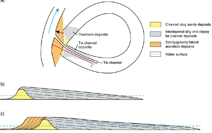
Figure 5.1: Schematic representation of the channel plug length and growth pattern based on bifurcation and
channels geometry and downstream hydraulic effects. 161
Figure 5.2: The Bassée alluvial plain context. Simplified geological map of the Seine River basin (a).
Catchment area of the Bassée alluvial plain and current Seine course (b). Geomorphologic map of the downstream part of the Bassée alluvial plain showing the Old Seine paleo channels reconstruction and the studied channel position (c). Schematic cross-section of the Bassée alluvial plain (d). Deleplancque et al. (2018) and Petit et al. (in press), adapted from Mégnien et al. (1965). 163
Figure 5.3: Current channel morphology. Aerial picture and boreholes position (a). Lidar DEM and
cross-sections positions (b). 164
Figure 5.4: Interpreted cross-sections. A, B and E from Petit et al. (in press). 166
Figure 5.5: Interpreted coarse-grained deposits map. 167
Figure 5.6: Close-up on the Vimpelles channel plug deposits showing its topographic step and the downstream
variations in coarse deposits fill volume. 168
Figure 5.7: Reconstruction of the temporal and morphologic evolution of the Vimpelles channel. 171
Figure 5.8: The Boire Torse channel localisation and the cross-sections position, after Arthuis et al. (2015) and
Miéjac & Arthuis (2007). 174
Figure 5.9: Channel cross-sections in the Boire Torse and measurement method. Cross-sections from Miéjac &
Arthuis (2007). 175
Figure 5.10: Location and geology of the studied area showing the Rijnstrangen disconnected channel (a) and
laser altimetry view of the Rijnstrangen channel with the cross-sections positions (b). From Toonen et al. (2012).
176
Figure 5.11: Interpreted cross-sections of the channel fill geometry in the Rijnstrangen channel. a: Bioturbated
non-laminated clays. b: Calcareous, humic finely laminated (<1 cm) clayey silts showing flood pulses. c: Calcareous, humic laminated (1-3 cm) silts showing flood pulses. d: Calcareous, coarsely laminated (>3 cm) silty sands showing flood pulses and plant debris. e: Gravels and sands. From Toonen et al. (2012). 177
Figure 5.12: Percentage of coarse-grained fill deposits in cross-sections in function of the distance to the
channel bifurcation point for 5 different river channels. 178
Figure 5.13: Lower Mississippi Valley position along the Mississippi River reach and situation of the Yazoo and
xviii
Figure 5.14: Examples of the typical geometries mapped in the Lower Mississippi Valley and illustrations of the
criterions used for channel selection. Maps from Krinitzsky et al., 1965 Saucier, 1967. 183
Figure 5.15: Ain and Allier rivers and Lower Mississippi Valley (LMV) apparent channel plug length function
of the channel length ratio. 186
Figure 5.16: Conceptual sketch representing channel fill deposits appearance at the end of the disconnection (a)
and the sediments architecture at the end of the channel fill (b). Differentiation and accurate mapping of the open-stage deposits can then only be made using coring (c-d). Cores are from Jordan & Pryor (1992). 187
Figure 5.17: Mississippi River abandoned channel fill in Hickman County (Kentucky). Boreholes position in the
channels (a). Borehole data taking into account the surface topography and longitudinal distance in the channel and interpreted facies longitudinal evolution (b-c). Data from Alexandrowicz (2015). 189
Figure A1: Final deposits of the 8 asymmetrical experiments, without and with levee breach. (a-b) β2 = 30°. (c-d) β2 = 45°. (e-f) β2 = 60°. (g-h) β2 = 90°. 217
Figure B1: Temporal evolution of the CHA site. 222
Figure B2: Temporal evolution of the MOL/MAR sites. 223
Figure B3: Aerial views of the closed stage of the five historical cutoffs (1954-1965) described in Table 4.1. 224 Figure C1: Aerial views of the closed stage of the five historical cutoffs (1946-1960) described in Table E2. 229 Figure D1: Location of each borehole in the Vimpelles channel. 232
Figure D2: Borehole sampling method. Coring using a hand auger (a). Samples retrieved using a hand auger (b)
and a Russian corer (c). Hand auger sampling is less continuous but allow sampling of sands and thin layers of fine gravels while the Russian corer can only sample peat, clays and silts. 233
Figure D3: Log of each of the 38 boreholes. Designation corresponds to the number of the GPS waypoint made
to locate the borehole. 234
List of Tables
Table 2.1: List of experiments and associated parameters. 49
Table 2.2: List of sand bed experiments and associated parameters. Sand bed volume is not accounted in sand
plug volume. 68
Table 2.3: List of base level variation experiments and associated parameters. 72
Table 3.1: List of the experiments and resulting channel plug characteristics. 88
Table 4.1: Summary of the studied channels characteristics. 128
Table 4.2: Sedimentary facies. 135
Table 4.3: Wolman Pebble Counts sampling data. 141
Table 5.1: Mississippi and Arkansas River channel plugs measurements. 184
Table A1: List of experiments and detail of all associated parameters. 216
Table B1: Hydraulic parameters, cross-sectional area and filled area of the cross sections displayed in Figures
4.3, 4.4 & 4.8. 225
1
Introduction
Channel abandonment is a ubiquitous process that allows the reorganization of fluvio-hydrological networks and sediment distribution in alluvial plain. Following the disconnection of parts of the river course, they form sinks for sediments while previously stored deposits are reworked by active channels. The nature, geometry and architecture of the abandoned channels sedimentary fill will impact the future evolution of the alluvial plain. For instance, fine-grained fills (clays or peat) are strongly cohesive that will reduce the lateral mobility of the active channel and narrow the meander belt. On the other hand, as the fraction of coarse-grained fill deposits increases in abandoned channels, hydraulic connectivity of floodplain sediment increases. Abandoned channels also have immediate economical value as fish nurseries, fluvial transportation hubs or touristic and leisure areas. Furthermore, abandoned channels have ecological values as they are diversity hotspots that can be used to bolster the population of endangered species or reintroduce them. Finally, the fine-grained part of abandoned channels usually preserves biogeochemical indicators and artefacts propitious to archaeological studies.
Channel abandonment initiate with the formation of a short plug of coarse deposits isolating the channel from the active one(s). This channel plug is described as a wedge-shaped sedimentary body formed by the bedload part of the sedimentary charge. After the channel disconnection and isolation from bedload sediment supply, finer-grained sediments brought by overbank events or autochtonous sedimentation such as plant detritus and peat deposits slowly heal the paleo-thread. Numerous studies have described coarse deposits in channels but limited studies focused on their extent in relation with geomorphic processes. Hence, numerical models devised to reconstruct the spatio-temporal evolution of channelized fluvial systems often assume a 100% clay infill of the abandoned channels in the sake of simplicity due to the lack of constraints on coarse-grained fill deposits architecture and extent.
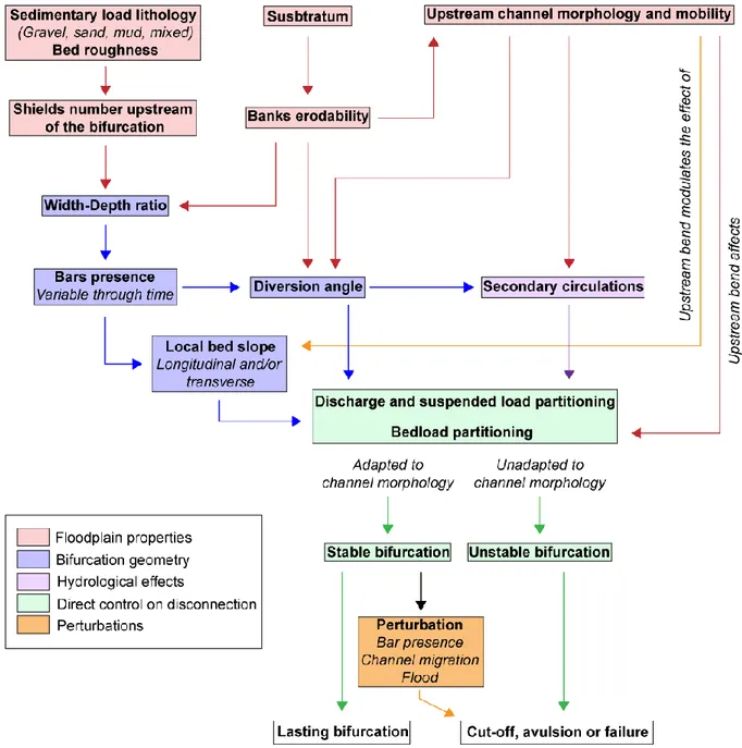
While it has been established that the bifurcation geometry before channel disconnection affects the local hydraulic dynamics and induces deposition, controls on coarse-grained fill sediments deposition are not well known. It has been suggested that the channel and bifurcation geometry controls the channel plug extent, for instance through bifurcation angle value or difference in slope between the two channels. However, few studies have quantified bifurcation dynamics throughout the whole disconnection process. Thus much remains to be
2
done to link hydrology, geomorphology and sedimentary deposits architecture. Currently, important progresses in the understanding of channel abandonment have been made using either field or modelling studies but only a few attempts have been made to link the two approaches.
This dissertation aims at linking channel geometry, hydraulic processes and coarse-grained fill sediments deposition and architecture in abandoned channels. The approach was process-based with at first a series of flume experiments whose results were compared to observations made on the field in channels abandoned by both mixed- and bedload dominated rivers. The dissertation is composed of six chapters:
Chapter 1 summarizes the current knowledge on channel abandonment and the resulting sedimentary fills with a focus on the coarse-grained bedload deposits.
Chapter 2 presents experimental data on channel abandonment using a flume with a modular bifurcation. The effects of diversion angle and water-surface variations are discussed. An architectural model for bedload deposits in abandoned channel is proposed.
Chapter 3 focuses on bedload deposition in curved experimental channels and discusses the influence of hydraulic effects on the sedimentation patterns in the abandoned channels.
Chapter 4 focuses on the architecture and temporal evolution of bedload deposits in several modern curved channels disconnected by chute cutoffs in the Ain River to tentatively link hydrology, sedimentation processes and bedload fill architecture. The Ain river was selected as its bedload dominated nature enables easy comparison with the flume experiments.
Chapter 5 discusses the long term preservation of bedload deposits in abandoned channels. The relationships that were experimentally determined between the channel plug architecture and forcing parameters are tested against field data acquired on well-documented mixed-load rivers such as the Seine and Mississippi rivers.
Chapter 6 summarizes the conclusions of this work and discusses possible next steps for bedload channel fill study.
5
Chapter 1: Channel abandonment and
infilling – Literature review
Ce chapitre présente une étude bibliographique sur les environnements dans lesquels se forment les chenaux abandonnés, leurs morphologies, processus de formation, ainsi que sur les facteurs contrôlant leur abandon et remplissage, et leurs interactions avec les autres objets géomorphologiques des plaines alluviales. Bien que cette étude bibliographique se décrive toutes les étapes du remplissage des chenaux abandonnés, elle se concentre sur les processus de dépôt et architectures des dépôts grossiers de charge de fond.
---
This chapter presents a literature review on abandoned channels environments, morphology and formation as well as on the nature and geometry of their fills, the controls on their abandonment and infilling and their relation with the other features of the floodplain. Although this literature review describes all stages of abandoned channel infilling, it focuses heavily on the deposition processes and architecture of the coarse-grained bedload deposits.
6
1.1. Introduction
Abandoned channels are widespread features in floodplains across the planet. They form as the result of avulsions or cutoffs associated with river migration and aggradation. As they form elongated topographic depressions, the abandoned channels are efficient sediments sinks (Aalto et al., 2008; Lauer & Parker, 2008; Dieras et al., 2013). Abandoned channels are studied for a broad range of applications. The lithology, architecture and geometry of abandoned channels infilling have a significant impact on the latter evolution and physical properties of the floodplain (Howard, 1992; Smith et al., 1998; Flipo et al., 2014; Schwendel et al., 2015), making it an economical (agriculture, fluvial transportation, nautical sport areas) and societal (flood risk, urban areas extension) matter. Abandoned channels also form wetlands that are ecological hotspots (Novitzky et al., 1996; Ward et al., 1999), serving as fish nurseries or endangered species reintroduction sites. Their infilling form archeological and quaternary paleo-climatic archives (van Dinter et al., 2017), where archeological artifacts can be found together with organic matter used for isotopic dating, pollens, fossils or sedimentary evidences of extreme events. Finally, heterogeneities formed in abandoned channels preserved in the fossil record influence the geological fluvial reservoir architecture and connectivity (Miall, 1996; Willis & Tang, 2010; Colombera et al., 2017; Cabello et al., 2018), with implications for natural resources exploitation.
1.2. Fluvial systems
Fluvial systems are formed by one or several active channels that are migrating in a floodplain. The floodplain corresponds to the domain that is flooded during overbank floods, while the area occupied by the channel path through time forms the channel belt. There are four main types of fluvial systems that form depending on the floodplain characteristics and the sediment supply: straight, braided, anastomosed and meandering (Leopold & Wolman, 1957; Rust, 1978; Church, 2006).
Straight channels develop along fault lines or on steep slopes, and in some deltas. They often incise a narrow and deep valley or a canyon (Fig. 1.1a). It is unusual for a straight channel to be absolutely straight for a distance greater than 10 channel widths, and they show only limited inflexion of their course (Leopold & Wolman, 1957). They develop a riffle and pool morphology (Fig. 1.2), with a spacing between riffles and pools approximately equal to 5 channel widths (Leopold & Wolman 1957, 1960). It is believed by Wolman & Leopold
7
(1957) that the mechanisms leading to channel meandering appear to occur in straight channel but that meandering is hindered by the valley slope or narrowness.
Braided systems sediment conduits are characterized by a single, low sinuosity channel at bankfull. At lower regime it consists of a network of channels separated by gravely banks, set in the conduit (Fig. 1.1b, 1.2; Leopold & Wolman, 1957; Miall, 1996). The gravel banks are generally unstable and are reworked and displaced during floods. When the floods are sufficiently frequent and no vegetation stabilizes the banks, channels can be highly mobile and unstable. Braided rivers are characterized by high width/depth ratios (W/D ratios) (>50) (Fig. 1.3a), steep slopes and low sinuosity (<1.3) (Miall, 1977; Bridge, 2003). Due to their steep slopes and general proximity to reliefs, braided systems carry a relatively coarse-grained sediment load.
Figure 1.1: Satellite images of the four major types of fluvial systems. (a) Straight river (Gunnison River, USA). (b) Braided river (Rakaia River, South Island, New Zealand). (c) Anastomosed river (Columbia River, Canada). (d) Meandering river (Tchoulym River, Russia). Source: Google Earth Pro.
Anastomosed systems are formed by several, well differentiated channels separated by stretches of the floodplain, forming vegetalized, perennial islands that are not reworked during floods (Fig. 1.1c, 1.2). The channels are stable and can take several morphologies depending on the floodplain characteristics. They can be straight or sinuous, in which case they are deep and narrow, with very abrupt banks (Fig. 1.3b; Rust, 1978; Miall, 1996), or have a meandering pattern. Anastomosed threads have a low W/D ratio (<40) and a low slope, and dominantly carry fine-grained sediments. Anastomosed rivers were sometimes called anabranching rivers (Smith & Smith, 1980; Rust, 1981; Schumm, 1985), but the definitions
8
are variable, relying either on the stability or cohesiveness of the banks or the size of the islands. For instance, Nanson & Knighton (1996) integrated the notion of anabranching river in all types of fluvial systems, as rivers comprised of “multiple channels separated by vegetated semi-permanent alluvial islands excised from existing floodplain or formed by within-channel or deltaic accretion”. As such the definition of anabranching river is very broad. To differentiate anabranching rivers from anastomosed rivers, Makaske (2001) proposes the following definition for anastomosed rivers: “Anastomosed systems are formed by two or more interconnected channels that enclose floodbasins”, which couples channel pattern and floodplain geomorphology while excluding the braided systems.
Meandering systems generally form the distal part of the fluvial system. They are characterized by a single active, highly sinuous channel with some tributaries, notably chute channels (Fig. 1.1d, 1.2) (Allen, 1965; Miall, 1996; Bridge, 2003). They are set in low slopes environments and carry a mixed sediment load. Point bars are formed on the inner part of the meander bends in association with the migration and erosion towards the outer bank that generally occurs during floods (at least full bank, and also overbank). Channels are flanked by levees formed of silt and fine sand draping the edges of the channels during overbank flooding events (Fig. 1.3c; Allen, 1965, Miall, 1996). The levees can be breached, generally during floods (Slingerland & Smith, 2004) although bank failure, animal or debris dams, the formation of ice or log jams and the migration of bars downstream can lead to levee crevassing (Jones & Schumm, 1999). Part of the flow is diverted through the crevasse channel and this result in the formation of crevasse-splays, wide and thin sand-sheets that form on the floodplain (Allen, 1965; Smith et al., 1989). The deposits associated to the channel and its migration (i.e., point bars, levees, channel fill) form the meander belt, which is the part of the alluvial plain where the active channel migrates (Fig. 1.1d).
These major systems form the extreme poles in the classification. Yet the transition from one style to another is not sharp, and there are overlaps in conditions allowing two different styles. Thus some rivers share the characteristics of two of the main fluvial systems (Fig. 1.2), due to floodplain conditions such as slope, sediment erodibility or sediment supply falling at the limit between the ideal ranges for two distinct fluvial systems morphologies. Anabranching rivers, described earlier, regroup the characteristics of anastomosed and braided or meandering rivers (Nanson & Knighton, 1996). Wandering rivers are formed by one to two active sinuous channels hosting mid-channel bars, at the interface between braided and meandering rivers (Miall, 1996; Church, 2006) while low-sinuosity rivers can be found at the
9
interface between braided and anastomosed systems. In these low-sinuosity active channels, alternate bars are formed by lateral accretion before migrating downstream (Crowley, 1983; Miall, 1996).
Figure 1.2: Diagram showing the variety of morphologies taken by rivers between the dominant types when the
control factors vary. The main channel types are located at the appropriate positions within the diagram. Shading is intended to reflect sediment character. From Church (2006).
10
1.3. Floodplain dynamics and resulting sedimentary facies
Coarse sediments are mostly deposited and reworked during flooding events and the associated channel migration. Evolution of channel paths occurs by two major processes. The first is the channel migration by lateral erosion. In that case, when the floodplain is wide and the channels stable, migration is slow and the sand bodies are few and isolated. When migration is fast, channel abandonment is frequent and the sand bodies are numerous and interconnected (Miall, 1996). The second migration process is avulsion, when the river finds a new course. When avulsions are frequent, numerous, interconnected sand bodies will also be deposited.
Figure 1.3: Representation of the typical planform and vertical geometry of the deposits formed by three major
types of fluvial systems in aggrading setting. (a) Braided rivers. Low lateral mobility. (b) Anastomosed river. Lateral migration and avulsions. (c) Meandering river. Lateral migration. From Jerolmack & Mohrig (2007).
Channel migration and avulsion deposits sediments in a specific planform organization depending on the fluvial system type (Figs. 1.1 & 1.3). They also rework and erode previously deposited sediments, which in a graded system results in a near constant amount of coarse deposits in the floodplain as the material eroded at a point of the floodplain is deposited downstream at another point. When the system aggrades, the sand bodies stack vertically (Fig. 1.3; Miall, 1996). In the aggradation rate is high, the sand bodies can be vertically disconnected from each other. However, when the aggradation rate is appropriate, the combined lateral and vertical accumulation of coarse-grained fluvial deposits results in interconnected sand bodies that can form fluvial reservoirs (Fig. 1.4; Bridge, 2003). In this
11
intricate network of sedimentary bodies formed by the spatial and temporal evolution of the floodplain, the potential contrasts in physical properties, such as erodibility or permeability, between the deposits may impact both the future evolution of the floodplain and the reservoir properties. This section describes the architecture and facies of the sedimentary bodies found in the channel and alluvial plain, in relation to which abandoned channels are formed.
Figure 1.4: One example of floodplain cross section using a Flumy simulation (Lopez et al. 2008) that shows the
spatial relationships between the abandoned channels and other lithofacies in a fluvial meandering reservoir.
1.3.1. Channel migration deposits and associated facies
Channel migration creates coarse-grained (gravels and sand) sedimentary bodies in floodplains by complex processes that are affected by both the channel evolution and geometry itself (Willis, 1989) and the complex flow dynamics in the channel (Leopold & Wolman, 1960; Allen, 1963, 1965, 1970a; Nanson, 1980; Robert, 2003; Fustic et al., 2012). Although they are generally considered to be good reservoir deposits, the resulting sedimentary bodies have a complex internal architecture with much heterogeneity at many different scales (Barton, 1994; Labrecque et al., 2011a; Deschamps et al., 2012). Channelized deposits can be divided in two groups: channel bed deposits and bars.
Channel lag deposits form the channel bed. They correspond to channelized gravels or sands deposits with a convex erosive base and a fining-upward trend. They are generally formed by several successive sequences separated by erosion surfaces (Miall, 1996) and composed of massive sandstones or conglomerates whose thickness varies depending on the scale of the channel (Miall, 1996; Labrecque et al., 2011a, 2011b). They may offer a sharp lithological contrast with the surrounding sediments,
12
being generally deposited on clay, silts or finer sands, surmounted by finer sands and bracketed by clays (Figs. 1.4 & 1.5a; Donselaar & Overeem, 2008) and present many erosion surfaces that create yet more lithological contrasts inside the channel lag deposits.
Longitudinal sandbars are dynamic structures that evolve within the channel. They can be found inside the channel of braided, straight or anastomosed systems, or anchored to the channel bank (Miall, 1977, 1996). They form thin and elongated fining-upward bodies formed by downstream accretion and lateral accretion on their edges (Miall, 1996). They form nodes that can capture dunes that were migrating downstream on the channel bed (Cant & Walker, 1978). Consequently these bars are formed by successive accretion layers of various grainsizes with different orientations and dips and some erosional surfaces, resulting in highly heterogeneous sedimentary bodies (Cant & Walker, 1978; Miall, 1996).
Point bars are formed in association with the lateral migration of meander bends in meandering and anastomosed systems through erosion of the external bank of the bend (Allen, 1963; 1970a). On the internal bank they form accretion layers in a sigmoidal shape angling towards the channel with a 5 to 25° dip (Miall, 1979). Due to the varying effects of the channel shape on sediment deposition along the point bar length, point bars may have a very complex internal architecture. Macro-scale heterogeneities are formed by the fining-upward of the deposit across the whole point bar (Fig. 1.5a; Allen, 1970b; Walker, 1984), as well as the fining downstream and from the centre to the edge of the point bar (Fig. 1.5b; Bridge et al., 1995; Deschamps et al., 2012; Fustic et al., 2012; Durkin et al., 2015, 2017). Chute channels formed during floods (but not necessarily leading to chute cutoff) on top of the point bar that incise part of the point bar deposits (Fig. 1.5b) create erosion surfaces which are filled with heterogeneous material generally finer than the point bar deposits themselves (Deschamps et al., 2012; Colombera et al., 2017; Cabello et al., 2018). They form another set of heterogeneities inside of the point bar. Meso-scale heterogeneities inside the point bar are formed by changes in lithology or reworking of the deposits. During meander migration and rotation, part of the point bar is reworked, creating erosional surfaces overlain by new, discordant accretion sets that can have a different orientation, dip and grain size (Durkin et al., 2015). Furthermore, clay drapes forming permeability baffles can be deposited amongst the lateral accretion deposits in case of low-energy flow (Leopold & Wolman, 1960; Nanson, 1980; Robert, 2003; Pranter et al., 2007; Fustic et
13
al., 2012). These drapes are rare in point bars, except when a tidal effect reaches the meander bend (Deschamps et al., 2012). However they are more common in counter point bar deposits, the concave deposits connected to the downstream part of the point bar (Smith et al., 2011) where the flow energy is lower. Finally at the micro-scale grain size variations inside each set exist.
Fig. 1.5: Architecture, grainsize evolution and heterogeneities across a point bar. (a) Typical depositional
sequence of meandering channel deposits (from Donselaar & Overeem 2008). (b) Internal architecture of a point bar displaying internal facies heterogeneities (from Deschamps et al. 2012).
1.3.1. Overbank deposits and associated facies
Most of the floodplain deposits are overbank deposits formed during flooding event. They are finely-grained sediments that become finer when the distance to the active channel increases. Overbank facies form a significant amount of the floodplain deposits in meandering and anastomosed systems, whereas the braided system channel network tends to occupy most of the floodplain (Miall, 1996). Two types of overbank deposits exist:
The coarse-grained deposits form the levees and crevasse splays. Levees are deposited on the edge of the channels during overbank floods when suspended sediments overspill (Figs. 1.2; 1.4). They form a wedge-shaped deposit whose thickness and grain size decreases with the distance from the channel (Smith et al., 1989; Miall, 1996). Levees are formed by the aggregation of thin layers with a grainsize typically ranging from fine sands to silts. Paleosoils as well as animal and/or vegetal bioturbation can typically be found in the levees. Crevasse splays form when the flow breaches the levees, creating a crevasse channel. The crevasse channel itself forms sand ribbons with cross stratification and current ripples (Miall, 1996). When the flow reaches the floodplain it spills out and loses energy, inducing sediment settling forming thin lobe-shaped deposits with an important horizontal extension (Smith et al., 1989; Miall, 1996). Crevasse splays grainsize decreases vertically and