UNIVERSITÉ DU QUÉBEC À MONTRÉAL
DISPERSION OF CARBON MA TERIALS BY CHOLESTEROL BASED
POLYMERS IN ALKANE SOLVENTS
THE SIS PRESENT AS PARTIAL REQUIREMENT FORDOCTORATE IN CHEMISTRY BY AHMAD AL SHBOUL MARCH 2018
Service des bibliothèques
Avertissement
La diffusion de cette thèse se fait dans le respect des droits de son auteur, qui a signé le formulaire Autorisation de reproduire et de diffuser un travail de recherche de cycles supérieurs (SDU-522 - Rév.0?-2011 ). Cette autorisation stipule que <<conformément à l'article 11 du Règlement no 8 des études de cycles supérieurs, [l'auteur] concède à l'Université du Québec à Montréal une licence non exclusive d'utilisation et de publication de la totalité ou d'une partie importante de [son] travail de recherche pour des fins pédagogiques et non commerciales. Plus précisément, [l'auteur] autorise l'Université du Québec à Montréal à reproduire, diffuser, prêter, distribuer ou vendre des copies de [son] travail de recherche à des fins non commerciales sur quelque support que ce soit, y compris l'Internet. Cette licence et cette autorisation n'entraînent pas une renonciation de [la] part [de l'auteur] à [ses] droits moraux ni à [ses] droits de propriété intellectuelle. Sauf entente contraire, (l'auteur] conserve la liberté de diffuser et de commercialiser ou non ce travail dont [il] possède un exemplaire.,
UNIVERSITÉ DU QUÉBEC À MONTRÉAL
DISPERSION DES MATÉRIAUX DE CARBONE À L'AIDE DU POL YMERE À
BASE DU CHOLESTÉROL DANS LES SOLVANTS ALCANES
THÈSE
PRÉSENTÉ
COMME EXIGENCE PARTIELLE
DU DOCTORAT EN CHIMIE
PAR
AHMAD AL SHBOUL
1 express my sincere gratitude to my supervisors, Pr. Jerome Claverie and Pr. Mohamad Siaj, who patiently guided and assisted me throughout ali my studies at Université du Québec à Montréal (UQAM). 1 will forever be indebted to their guidance. They gave me the opportunity to work in this fascinating area of research, also they trusted in my research and its results. 1 acknowledge my thesis exan1ining committee members, Pr. Rafik Naccache from Concordia University, Pr. Daniel Bélanger and Pr. Mathieu Frenette from UQAM for taking the time to review my thesis and provide valuable feedback.
1 would like to extend special thanks to the technical staff at UQAM, especially Dr. Gwenaël Chamoulaud. 1 would like to thank my colleagues in the research teams of both Pr. Claverie and Pr. Siaj for their friendship and assistance. Thanks for the graduate director Pr Sylvain Canesi, Pr Huu van Tra and Madam Sonia Lachance, who helped me through ali my studies. Thanks for Mr. Luc Arsenault, who has an amazing personality.
My heartfelt thanks go to my beloved family. Mom, I am here today because of you. Dad, you are always the inspiration for me. Your encouragement and support are endless. Thanks to my sisters and brothers for their kindnesses, supports, and encouragements. Finally, to my caring, loving, and supportive wife, Lamia: My deepest gratitude. You were supportive and strong in this long and bumpy journey. Your endless patience and encouragement are so appreciated and duly noted. My beloved daughter Mariem and son Mohamed Alameen, you will understand these words when you start reading, thank y ou so much for being the source of my happiness and the jo y of my !ife. 1 love you ail.
Il TABLE OF CONTENTS ACKNOWLEDGMENTS ... I TABLE OF CONTENTS ... II LIST OF FIGURES ... V LIST OF TABLES ... X LIST OF ABBREVIATIONS ... XI RESUME ... XV ABSTRACT ... XVII CHAPTER 1 ................................................................. 1 INTRODUCTION ... 1 1.1 ÜRAPHENE ... 1 1.1.1 Synthesis of graphene ... 2
1.1.2 Integration of graphene in electronic deviees ... 6
1.1.3 Formulation ofthe graphene-based ink ... 7
1.2 CARBON NANOTUBES (CNTS) ... 26
1.2.1 Synthesis SWNTs ... 28
1.2.2 Post-treatment ofnanotubes ... 29
1.2.3 Applications of SWNTs ... 46
CHAPTER 2 ... 48
SCIENTIFIC ARTICLE ... 48
GRAPHENE DISPERSIONS IN ALKANES: TOWARD FAST DRYING CONDUCTING INKS ... 48
CONTRIBUTION OF THE MAIN AUTHOR AND THE CO-AUTHORS ... 49
2.1 ABSTRACT ... 51
2.2 INTRODUCTION ... 51
2.3 EXPERIMENTAL SECTION ... 55
2.3.1 Materials and synthesis ... 55
2.3.2 Preparation of exfoliated graphene: Building of the adsorption isotherm .... 55
2.3.3 Graphene ink preparation ... 56
2.3.4 Characterization ... 57
2.3.5 Conducting ink deposition and analysis ... 58
2.4 RE SUL TS A D DISCUSSION ... 59
2.4.1 Preparation of exfoliated graphene and adsorption isotherm ... 59
2.4.2 Nanostructure characteristics for the exfoliated graphene: Chemical and structural analysis ... 62
2.4.3 Graphene-based inks ... 67
2.5 CONCLUSIONS ... 71
CHAPTER 3 ... 73
SCIENTIFIC ARTICLE ... 73
A SELECTIVE PROCESS TO EXTRACT HIGH-QUALITY REDUCED GRAPHENE OXIDE (RGO) LEAFLETS ... 73
CONTRIBUTION OF THE MAIN AUTHOR AND THE CO-AUTHORS ... 74
3.1 ABSTRACT ... 76
3.2 INTRODUCTION ... 76
3.3 EXPERIMENTAL SECTION ... 79
3.3 .1 Synthesis of poly(CEM 11-b-EHA 7 ), GO and RGO: ... 79
3.3.2 Preparation ofRGO dispersion: ... 79
3.3.3 Characterization: ... 80
IV
3.4.1 Extraction ofRGO in isooctane ... 81
3.4.2 Chemical and structural analysis of extracted RGO ... 83
3.5 CONCLUSIO ··· 89
CHAPTER 4 ... 91
CONCLUSION AND PROSPECTIVE ... 91
APPENDIX A ... 97
SUPPORTING INFORMATION FOR ... 97
GRAPHENE DISPERSION IN ALKANES: TOWARD FAST DRYING CONDUCTING INKS ... 97
A.1 CO FOCAL RAMAN MICROSCOPY ... 98
A.2 X-RA Y PHOTO ELECTRON SPECTROMETRY (XPS) ... 101
A.3 ATOMIC FORCE MICROSCOPY (AFM) ... 102
A.4 SCANNING ELECTRON MICROSCOPY (SEM) ... 104
A.5 INK DRYING RATE MEASUREMENT ... 108
A.6 CONTACT ANGLE MEASUREMENTS ... 109
APPENDIX B ... 113
SUPPORTING INFORMATION FOR ... 113
A SELECTIVE PROCESS TO EXTRACT HIGH-QUALITY REDTJCED GRAPHENE OXIDE (RGO) LEAFLETS ... 113
B.l FOURIER TRANSFORM INFRARED SPECTROSCOPY (FTIR) ... 114
B.2 X-RA Y POWDER DIFFRACTION (XRD) ... 115
LIST OF FIGURES
Figure 1.1: Graphene and other carbon allo tropes ... 2 Figure 1.2: Schematic illustration of the synthetic protocols for graphene. (A) Micromechanical cleavage. (B) Anodic bonding. (C) Laser vaporization (photo -exfoliation). (D) LPE of graphite. (E) Growth from SiC. (F) Precipitation from carbon containing metal substrate. (G) CVD process. (H) Molecular bearn epitaxy. (I) Chemical synthesis. (J) LPE of GO. Reproduced from reference.33 ... .4 Figure 1.3: Examples of the deposition techniques for the LPE graphene. (A) Dip casting of LPE graphene, (B) Rod coating, (C) Spray coating and (D) Inkjet printing. Reproduced from reference.33 ... 6 Figure 1.4: Map of the (n,m) integers indicated on a graphene sheet, and an example of zigzag and armchair nanotubes ... 27 Figure 1.5: A schematic representation of the synthetic methods of SWNTs. (a) Arc discharge, (b) CVD, and (c) laser vaporization. Reproduced from reference.15529 Figure 1.6: Separation of SWNTs by dielectrophoresis. The separation mechanism of
the dielectrophoresis through using an H-shaped microfluidic channel. The labels P, M and Sare corresponding to the raw dispersion ofSWNTs, rn- and sc-SWNTs, respectively. Reproduced from reference.172 ... 31 Figure 1.7: Separation ofSWNTs by DGU. (A) A photograph and absorption spectra
of the CoMoCAT-grown SWNTs after separation based on their variation of diameter and band-gap. (B) A photograph and absorption spectra of the laser-ablation-grown SWNTs after separation based on their electronic type to produce m-SWNTs (blue) and sc-SWNTs (red). Reproduced from reference.177 ... 32 Figure 1.8: A schematic diagram of the separation of SWNTs using a gel-packed column. The labels M and S correspond to rn- and sc-SWNTs, respectively. Reproduced from reference. 189 ... 34
VI
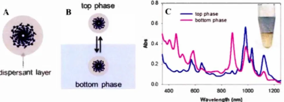
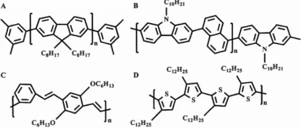
Figure 1.9: (A) A schematic illustration of a dispersant coating SWNT. (B) A schematic illustration of ATPE system. (C) UV-Vis-NIR absorption spectra of CoMoCAT SWNTs separated using a PEG/DX A TPE system. The inset shows the two phases of a PEG/DX ATPE system. Reproduced from reference.199 ....• 36 Figure 1.10: Conjugated polymers used to adsorb on SWNT (A) Poly(9,
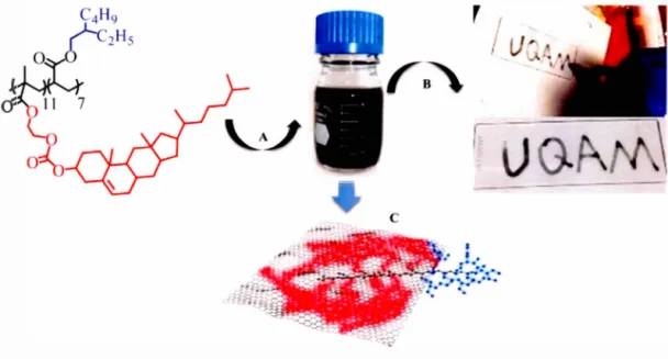
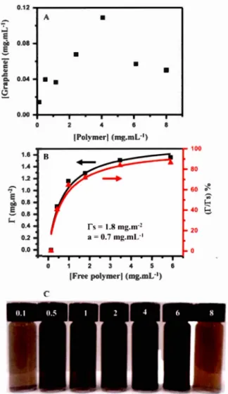
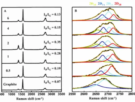
9-dioctylfluorenyl-2, 7 -diyl), PFO. (B) Poly(N-decylcarbazole-2, 7-diyl-alt-naphthalene-1 ,5-diyl), P4. (C) Poly[(m-phenylenevinylene )- alt -(p-phenylenevinylene)], PrnPV. (D) Regioregular poly(3-dodecylthiophene), rr-P3DDT ... 39 Figure 2.1: Preparation of the graphene ink in isooctane. A. Exfoliation of graphite in isooctane containing the diblock copolymer poly(CEM,,-b-EHA7) (CEM: Cholesteryloxycarbonyl-2-hydroxymethacrylate, EHA: 2-ethylhexyl acrylate) B. After purification and concentration of the graphene dispersion, a stable graphene ink is obtained. Graphene ink is used to fill a ballpoint pen, allowing direct writing of graphene on paper or glass. C. Schematic illustration of the adsorbed poly(CEM11-b-EHA7) on a graphene leaflet. The cholesterol part (in red) is adsorbed on graphene through non-covalent supramolecular interactions whereas the ethyl-hexyl part (in blue) is soluble in the solvent. ... 53 Figure 2.2: Graphene dispersion in isooctane stabilized by poly(CEM,,-b-EHA7). (A) Concentration of graphene vs total pol ymer concentration (free and adsorbed) (B) Adsorption isotherm: Surface coverage (left) or % surface covered (right) vs concentration of pol ymer free in solution, Crree (C) Images of the dispersions for various total pol ymer concentrations in mg.mL -I ... 60 Figure 2.3: Raman characterization of the graphene flakes by confocal Raman microscopy. (A) Raman spectrum of the flakes for different polymer concentration given in mg.mL-1 (obtained by averaging the Raman signal of 5 to 10 flakes over the en tire flake ). (B) Deconvolution of the 2D band ... 64 Figure 2.4: AFM characterizations of exfoliated graphene. A. Before removing unbound polymer. B-D After removing free polymer and purification by gentle
centrifuge of the graphene dispersion. AFM image of graphene flakes exfoliated with polymer concentration (B) 0.5 mg.mL- 1, (C) 1 mg.mL- 1, and (D) 2 mg.mL- 1 . ... 65 Figure 2.5: (A) Direct writing of graphene with a graphene ink loaded in a ballpoint
pen. B-D SEM images for films prepared by direct ballpoint writing of graphene ink (B) ink1 (rlf's = 23%), (C) ink2 (rlf's =65%), and (D) ink3 (rlf's =80%). 67 Figure 2.6: Electrical evaluation of the graphene ink. (A) Sheet resistance for graphene films prepared with the three inks. (B) Capacitance behavior of the graphene films based on the surface coverage of the graphene flakes. ( C) Sheet resistance of the graphene ink1 (rlf's = 23%) applied on various substrates ... 69 Figure 3.1: (A) Schematic representation of the DLPE process. RGO is layered with water and isooctane containing poly(CEM11-b-EHA7). Over time, high-quality RGO leaflets migrate in isooctane. (B) Structure of the diblock copolymer poly(CEM11-b-EHA7) (CEM: Cholesteryloxycarbonyl-2-hydroxymethacrylate, EHA: 2-ethylhexyl acrylate). (C) Photograph of RGO extracted by DLPE for 24 hours at pH=6, room temperature (RT) and 0.25 mg.mL- 1 polymer. It shows RGO separated in the biphasic aqueous (bottom layer) and isooctane (top layer) system. (D) Evolution of the isooctane layer vs time in hour (number indicated on the cap) for RGO extracted by DLPE at pH=6, RT, and 0.25 mg.mL- 1 polymer. ... 78 Figure 3.2: Concentration of the RGO extracted from aqueous to the organic medium (isooctane) after 24 hours of the DLPE process (A) vs extraction temperature (pH = 6 and c = 0.25 mg.mL- 1). (B) vs pH (pH = 6 and c = 0.25 mg.mL- 1) (C) vs poly(CEM11-b-EHA7) concentration (room temperature and pH= 6) . ... 82 Figure 3.3: Raman spectra and Io/IG of the RGO flakes extracted in isooctane by DLPE vs time of extraction (room temperature, pH= 6 and c = 0.25 mg.mL- 1) ... 85 Figure 3.4: (A) C 1 s XPS, and (B) PL spectra of GO, raw RGO and extracted RGO by DLPE (room temperature, pH= 6 and c = 0.25 mg.mL- 1) ... 86 Figure 3.5: (A, B) AFM images and height profiles ofRGO flakes extracted by DLPE
Vlll
substrate (room temperature, pH = 6 and c = 0.25 mg.mL-1) and collected on a n1ica surface ... 87 Figure 3.6: TGA curves (1 0 °C/min under air) of GO, of the cholesterol-containing polymer, of RGO before extraction, of RGO extracted in isooctane by DLPE (room temperature, pH= 6 and c = 0.25 mg.mL-1) and of the unextracted portion ofRGO ... 88 Figure A.l: Raman images of graphite (A (1-5)) and of graphene flakes (B-F (1-5)). Graphene flakes were prepared with different polymer concentrations B(l-5) 0.5 mg.mL-1, C(l-5) 1 mg.mL-1, D(l-5) 2 mg.mL-1, E(l-5) 4 mg.mL-1, F(l-5) 6 mg.mL-1• All the images have been treated the Gaussian filter and are color-coded according to Io/IG ratio ... 100 Figure A.2: C 1 s XPS spectra of graphene dispersion at different pol ymer concentration (a) 1.0 (b) 4.0 (c) 6.0 mg.mL-1, and deconvolution in C=C (red), C -C (blue) and C-0 (green) peaks ... 101 Figure A.3: AFM images of graphene flakes before removing the unbound polymer. ... 102 Figure A.4: AFM images of graphene flakes prepared after removing the unbound pol ymer. ... 103 Figure A.5: SEM images of the films prepared with graphene inks (0.5 mg.mL-1, rlrs
= 23%) written with a ballpoint pen on aluminum foi!. ... 104 Figure A.6: SEM images of the films prepared with graphene inks (1 mg.mL-1, r!fs = 65%), written with a ballpoint pen on glass on aluminum foi!. ... 105 Figure A.7: SEM images ofthe films prepared with graphene inks (2 mg.mL-1, r!rs =
80%), written with a ballpoint pen on glass on aluminun1 foi!. ... 105 Figure A.8: SEM images ofthe films prepared with graphene inks (0.5 mg.mL-1, rlfs
= 23%) transferred to untreated glass plates via a Langmuir-Blodgett transfer technique ... 106 Figure A.9: SEM images of the films prepared with graphene inks (1 mg.mL-1, rlfs =
65%) transferred to untreated glass plates via a Langmuir-Blodgett transfer technique ... 1 06 Figure A.lO: SEM images of the films prepared with graphene inks (2 mg.mL-1, rf[ s
=
80%) transferred to untreated glass plates via a Langmuir-Blodgett trans fer technique ... 1 06 Figure A.ll: Raman spectrum and graphitization degree (Iolla) of the films obtained by Langmuir-Blodgett transfer to glass. The graphitization degree (lolla) and polymer concentration used for the preparation of the ink are indicated in the figure ... 107 Figure A.12: SEM images of the films prepared with graphene inks (0.5 mg.mL-1, rlrs=
23%) transferred to HMDZ-treated glass via a Langmuir-Blodgett transfer technique ... 1 07 Figure A.13: SEM images of the films prepared with graphene inks (0.5 mg.mL- 1, [/[s= 23%) transferred to polymer treated glass via a Langmuir-Blodgett transfer technique ... 1 08 Figure A.l4: SEM images of the coated pol ymer/glass plates ... 108 Figure A.lS: A. FTIR spectrum of isooctane vs time. B. FTIR spectrum of graphene ink (c = 0.5 mgmL-1) vs time. C. %loss of the intensity of the isooctane and graphene ink vs time. At 125 s, isooctane is fully dried, while 50% of isooctane in the graphene ink was evaporated. At 250 s, the graphene ink is full y dried. 109 Figure A.16: Contact angle of graphene ink (c
=
0.5 mg.mL- 1) with various substrates. A. untreated glass plate. B. HMDZ-treated glass plate. C. Poly(CEM11-b-EHA7) coated glass plate ... 11 0 Figure B.l: FTIR of graphite, GO, as-obtained RGO powder and RGO extracted by DLPE process (24 hours). The verticalline indicates the epoxy band at 1055 cm -1 ... 115 Figure B.2: XRD diffraction of graphite, GO, RGO powder and RGO extracted byx
LIST OF TABLES
Table 1.1: Examples ofRGO-based inks ooooooooooooooooooooooooooo .. oooooooooooooooooooooooooooooooooooooo 11
Table 1.2: Examples ofnanocomposite inks based on GO and RGOOOOOOOOOOOOOOOOOOOOOOOOO 13
Table 1.3: Examples of graphene-based ink made of LPEO 0 0 0 0 00000 000 00 00000 000 0000 000 0 0 0 0 0 0 0 0 0 0 19
Table A.l: Average lo/IG for the edge and center of the graphene flakes convoluted
with the instrument functions nonlinear filters; Gauss fit and sum signal filterso ooooooooooooooooooooooooooooooooooooooooooooooooooooooooooooooooooooooooooooooooooooooooooooooooooooooooooooooooooooooooooooo99
Table A.2: Sheet resistance (Rs) of films prepared with graphene inks reported in
AFM ATPE ATR bp
c
CE CEM CMC CMs CNT CoMoCAT CRM CTABcv
CVD Cy DDGU
DLPE DMF LIST OF ABBREVIATIONSAtomic Force Microscopy Aqueous two-phase extraction Attenuated total reflectance Boiling point
Capacitance
Conductive electrode
Cholesteryloxycarbonyl-2-hydroxymethacrylate Carboxymethy lcell ulose
Carbon materials Carbon nanotube
Cobalt Molybdenum Catalyzed Confocal Raman microscope Cetyltrimethylammoniurn bromide Cyclic voltammetry
Chemical vapor deposition Cyclohexanone
Dipole moment
Density gradient ultracentrifugation Double Liquid-Phase Extraction Dimethylformamide
Xli
DOC Sodium deoxycholate
DSSCs Dye-sensitized solar cells
DWNT Double-wall carbon nanotube
DX Dextran
EG Ethylene glycol
EHA Ethyl-hexyl acrylate
EKC Electro-kinetic chromatography
EtOH Ethanol
FET Field-effect transistor
FT IR F ourier-transform Infrared
FTO Fluorine-doped tin oxide
GO Graphene oxide
HiPco high-pressure carbon monoxide
HMDZ Hexamethyldisilazane
HPMC (hydroxypropyl) methyl cellulose
HSP Hansen solubility parameter
Hyd hydrazine
IEC Ion-exchange chromatography
IPA Isopropyl alcohol
KSCN Potassium thiocyanate
LB Langmuir-Blodgett
LPE Liquid-phase exfoliation
MWNT M.Wt NIR NMP PEG
multi -wall carbon nanotube
molecular weight
N ear-infrared
N-methyl pyrrolidinone
Polyethylene glycol
PEDOT:PSS poly(3 ,4-ethylenedioxy thiophene ):poly( styrenesulfonate)
PET Polyethylene terephthalate
PFO Poly(9 ,9-dioctylfluorene)
PI PL PSS PTFE PVA PVC PVDF PVP RAFT RGO Rs RT
sc
SDBS SDS Polyimide Photoluminescence polystyrenesulfonate Polytetrafluoroethylene Poly(vinyl alcohol) Poly(vinyl chloride) Poly(vinylidene fluoride) Polyvinyl pyrrolidoneReversible addition-fragmentation chain transfer
Reduced Graphene Oxide Sheet resistance
Room temperature Sodium cholate
Sodium dodecylbenzene sulfonate
SEC SEM SiC SWNT m-SWNT sc-SWNT THF UQAM UV-Vis XPS XRD
r
rs
8 p Size-exclusion chromatography Scanning Electron Microscopy Silicon carbideSingle-wall carbon nanotube
Metallic single-wall carbon nanotube
Semiconducting single-wall carbon nanotube Tetrahydro furan
Université du Québec à Montréal Ultraviolet-visible
X -ray photoelectron spectroscopy X-ray powder diffraction
Surface coverage Full surface coverage Rolling angle
Conductivity
Resistivity
Extinction coefficient
Dispersive Hansen solubility paran1eter Polar Hansen solubility parameter H-bond Hansen solubility parameter Resistivity
Power conversion efficiency
RÉSUMÉ
Actuellement, une attention considérable est apportée sur la recherche et le
développement dans le domaine des appareils électroniques flexibles ou pliables, incitant ainsi des chercheurs à consacrer leurs travaux pour le développement de nouveaux matériaux électroactifs. En effet, ces matériaux doivent posséder des propriétés électriques semblables aux métaux conventionnels tels que le cuivre ou l'argent, avec l'élasticité et la grande maniabilité des polymères. Dans ce sens, la découverte de matériaux à base de carbone (CMs) plus précisément le graphène et les nanotubes de carbone (CNTs) a déclenché une révolution dans le domaine des nanosciences et des nanotechnologies. En effet, les CM présentent des propriétés physiques et chimiques extraordinaires qui peuvent être utilisées dans plusieurs domaines émergents. Toutefois, leur application sur une large échelle est limitée par plusieurs contraintes, telles que la qualité et la pureté du matériau recherché, le coût de production ainsi que la scalabilité des techniques de production.
Pour les CM, en plus des techniques d'exfoliation directe du graphène à partir du
graphite, l'oxydation chimique suivie par la réduction du graphite représente une des
méthodes les plus connues pour la production du graphène. Cependant, une telle technique conduit à la production de l'oxyde de graphène réduit (RGO) qui contient des domaines sp2 répartis sur une structure de carbone désordonnée. Ainsi, le RGO obtenu a des propriétés structurale et électrique inférieures à celui du pur graphène. Par ailleurs, dans le même ordre d'idées, les techniques de production des nanotubes de
carbone à monoparoi (SWNTs) génèrent des mélanges hétérogènes de nanotubes. Ces
mélanges contiennent des SWNT avec une chiralité, un diamètre, une longueur et une
conductivité électrique (métalliques ou semiconducteurs) différentes. Afin d'obtenir
les propriétés électroniques désirées de ces CM, il faut élaborer une méthode efficace pour les sélectionner et les purifier. Pour cette raison, nous avons développé dans ce travail un processus de séparation intitulé : double extraction en phase liquide (DLPE). Dans ce procédé, un polymère à base de cholestérol a été utilisé pour extraire le matériel carboné d'un solvant aqueux à partir d'un solvant organique.
Dans cette thèse, des matériaux à base de carbone de haute qualité et de polymère à base du cholestérol comme dispersant ont été préparés dans un milieu aqueux contenant des solvants d'alcanes à haute concentration. Par ailleurs, la méthode d'exfoliation directe du graphite a été utilisée pour la fabrication d'une encre conductrice à base du
graphène et à séchage rapide en présence d'isooctane. Une encre de graphène avec une
concentration plus élevée de l'ordre de 4 mg/mL a été développée. Ainsi, à l'aide d'un simple stylo à bille, 1' encre développée a pu être utilisée de manière fiable et répétée
-XVI
pour l'écriture sur des surfaces en verre. Le ratio graphène/polymère peut jouer un rôle crucial dans le contrôle et la stabilité de la dispersion, le revêtement de la surface ainsi que la continuité des films du graphène. Les propriétés structurelles et électriques des films de graphène ont été corrélées au revêtement de la surface par les flocons de graphène dispersés dans le cholestérol.
En résumé, nous avons utilisé dans ce travail la méthode DLPE pour la sélection des flocons du RGO en présence d'isooctane. On a pu déterminer que la stabilité colloïdale graphène/polymère est influencée par le pH de la phase aqueuse, la température ainsi que la concentration du polymère. Nous avons évalué la complexité de l'équilibre entre la stabilisation colloïdale du RGO et les paramètres opérationnels. Nous avons trouvé que le pH proche de la neutralité, la température ambiante et la concentration de 0,25 mg/mL du polymère, sont des paramètres opérationnels optimaux pour avoir une meilleure stabilité colloïdale. Notablement, des flocons de haute qualité sont collectés dans un milieu d'isooctane, laissant les feuilles de l'RGO d'une qualité moindre dans l'eau. La qualité des flocons de 1 'RGO a été déterminé par des méthodes de caractérisation telles que la spectroscopie Raman, la spectroscopie infrarouge à transformée de Fourier (FTIR), la spectroscopie photoélectronique à rayons X (XPS), la photoluminescence (PL) et le diffractomètre à rayons X (XRD).
Mots-clés : Matériaux à base de carbone, Graphène, Oxyde de Graphène Réduit, cholestérol du polymère, dispersion, Double Extraction en Phase Liquide.
--~----ABSTRACT
Flexible or foldable electronic deviees have attracted a considerable attention, leading
researchers to turn their attention toward the development of novel conducting and
semiconducting materials. Such materials possess the electrical properties of
conventional metals such as copper or silver, in addition to the elasticity and
processability of polymers. The discovery of carbon materials (CMs), specifically
graphene and carbon nanotubes (CNTs), has triggered a revolution in nanoscience and
nanotechnology fields. Indeed, CMs exhibit extraordinary physical and chemical properties for a vast range of potential applications. However, their deployment on a mass-scale is limited by various limiting steps, such the quality and purity of the material, the cost and scalability oftheir production techniques.
In this thesis, high-quality CMs dispersed in alkane sol vents at high concentration were prepared using a cholesterol containing polymer as a dispersant. Thus, a fast-drying
and conducting graphene ink was fabricated via direct liquid phase exfoliation (LPE)
of graphite in isooctane. A graphene ink with a concentration as high as 4 mg/mL was
developed. Using a commercial ballpoint pen, the ink could be reliably and repeatedly used for direct writing on glass slides. The ratio of graphene to polymer is crucial to control the dispersion stability, the surface coverage of the graphene flake by the polymer, and the connections between graphene flakes. Structural and electrical properties of graphene films were correlated to the surface coverage of the graphene flake by the cholesterol polymer.
Besides the direct exfoliation technique of graphene from graphite, chemical oxidation
and reduction of graphite is another well-known a mass-production process of
graphene. However, such technique leads to Reduced Graphene Oxide (RGO) which
can be viewed as a mixture of small clusters of sp2 domains distributed in a disordered
carbon structure. Thus, a material with inferior properties is obtained than the pristine
graphene. Similarly, production techniques of SWNTs generate heterogeneous
mixtures of nanotubes. Such mixtures contain SWNTs with different chiralities, diameters, Iengths, and electrical conductivities (i.e. metallic or semiconducting). In order to harvest the desirable electronic properties of such CMs, one must devise an efficient process to sort and purify these CMs. Therefore, in this work we have developed a separation process named Double Liquid-Phase Extraction (DLPE). In this process, a cholesterol-based polymer is used to extract a CM from an aqueous solvent to an organic solvent.
XVlll
stability is influenced by the pH of the aqueous phase, temperature and polymer concentration. Thus, we evaluated the intricate balance between the colloidal stabilization of RGO and operational parameters. The near neutra! pH, room temperature and 0.25 mg/mL of polymer were chosen as the optimal operational parameters for the best colloidal stability. Remarkably, flakes with high quality are collected in isooctane, leaving defectuous leaflets in water. The quality of RGO flakes was confirmed by Raman spectroscopy, Fourier Transform Infrared Spectroscopy (FTIR), X-ray photoelectron spectroscopy (XPS), photoluminescence (PL), and X-ray diffractometer (XRD).
Keywords: Carbon materials (CMs), graphene, Reduced Graphene Oxide (RGO), cholesterol-based polymer, dispersion, Double Liquid-Phase Extraction (DLPE).
INTRODUCTION
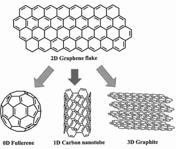
In recent decades, the development of innovative materials was the technological driver behind the nanoscience revolution. Still, there is a critical need to investigate novel materials that satisfy the demands of sophisticated technologies. Recently, carbon materials, CMs, have attracted an extraordinary attention in virtue oftheir remarkable properties such as mechanical strength, large surface area, high thermal conductivity, high electrical conductivity (cr) and excellent chemical stability. The 2D graphene flake is a bidimensional simple graphitic structural isomer from which ali other carbon allotropes can be derived (Figure l.l).(Novoselov et al., 2004) It can be stacked to form 3D graphite, rolled to form ID carbon nanotubes,(Iijima, 1991) or wrapped to form OD fullerenes.(Kroto, Heath, O'Brien, Curl, & Smalley, 1985)
1.1 Graphene
Since the discovery in 2004, graphene, a two-dimensional sheet of sp2 carbon atoms, has become the object of intense scrutiny in order to exploit its unique properties for a wide range of applications.(Geim & Novoselov, 2007) An ideal single-layer of graphene has a high Young's modulus (-lTPa), charge carrier mobilities (200,000 cm2N.s), a high thermal conductivity ( -2000 to 5300 W/m.K), a theoretical surface area of 2630 m2/g, an optical transmittance of 97.7% and a sheet resistance (Rs) of -100 0/seq.(Balandin et al., 2008; Bolotin et al., 2008; L. Chen et al., 2017; Gee et al., 2014; Mao et al., 2013; Nika, Pokatilov, Askerov, & Balandin, 2009; Novoselov et al., 2007; Novoselov, Geim, et al., 2005; Novoselov, Jiang, et al., 2005)
2
2D Graphene flake
OD Fullerene lD Carbon nanotube 3D Graphite
Figure 1.1: Graphene and other carbon allotropes
1.1.1 Synthesis of graphene
Graphene has been prepared through top-down (exfoliation from graphite) and
bottom-up (atom by atom growth) approaches (Figure 1.2).(Andrea C. Ferrari et al., 2015) The
main top-down approaches are the mechanical exfoliation,(Geim & Novoselov, 2007;
Novoselov et al., 20 12) liquid-phase exfoliation (LPE) of graphite,(Hernandez et al.,
2008; Lotya et al., 2009) chemical oxidation and reduction of graphite (LPE of
Graphene Oxide, GO),(Marcano et al., 2010; Zaaba et al., 2017) while the main bottom-up approaches are the heat treatment of silicon carbide (SiC),(Berger, 2006)
and chemical vapor deposition (CVD).(Jacobberger et al., 2015; Xuesong Li et al.,
3
include the unz1ppmg of CNTs,(Kosynkin et al., 2009) anodic bonding,(Shukla, Kumar, Mazher, & Balan, 2009) laser vaporization (photo-exfoliation),(Dhar et al., 2011) precipitation from a metal,(Winder, Liu, & Bender, 2006) molecular bearn epitaxy,(Garcia et al., 201 0) and chemical synthesis.(Annett & Cross, 2016; Cai et al., 201 0; Ruffieux et al., 20 16) The se preparation techniques lead to graphene flakes of variable quality and size. Furthermore, their scalability and cost are also highly variable.(Ren & Cheng, 2014)
Mechanical exfoliation was the first technique used to produce high-quality of graphene flakes directly from graphite flakes by using a scotch tape.(Geim & Novoselov, 2007) However, this technique is commonly used to produce monolayer or few-layer flakes of high quality for the scientific research. Heat treatment of SiC can produce graphene flakes through the evaporation of Si at temperatures higher than 1000 °C leading to graphene flakes with a high electron mobility in field-effect transistors (FETs) at room temperature.(Berger et al., 2004; de Heer et al., 2007; H. Huang, Chen, Chen, & Wee, 2008) However, their mobility is still lower than graphene produced from the natural graphite. Altematively, CVD whereby a hydrocarbon is decomposed at high temperature on a substrate, can be used to grow graphene on a large-area.(Bae et al., 201 0; K. S. K. S. Kim et al., 2009; X. Li et al., 2009) Still, this technique is limited by its cost and the necessity to transfer the produced flakes on the desired final substrate via a multistep process, which can complicate large-scale applications. The main challenge for these techniques is that they are impractical for industrial-scale production.
A D Micromechanical cleavage LPE
-
,.._
...
J Liquid exfoliation of graphene oxide J J._ ]. l l. J. l J '-x.[Ç"I :Ç.~hh:~ J c"-l 1 t Ix: J x:I .J "T "~Y rGraphite 8 E H
(
Hydtoxyl Anodic bonding Growth on SiC (00011 SU'aeo Epoxlde Molecular bearn epitaxy Graphene Oxidec
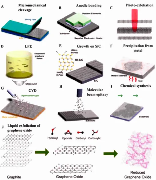
F Photo-exfoliation Precipitation from metal Chemical synthesis ~ Reduced Graphene Oxide 4Figure 1.2: Schematic illustration of the synthetic protocols for graphene. (A)
Micromechanical cleavage. (B) Anodic bonding. (C) Laser vaporization (photo-exfoliation). (0) LPE of graphite. (E) Growth from SiC. (F) Precipitation from carbon containing metal substrate. (G) CVD process. (H) Molecular beam epitaxy. (1) Chemical synthesis. (J) LPE of GO. Reproduced from reference.(Francesco Bonaccorso et al., 20 12)
5
Large-scale production of graphene has been achieved with LPE, where graphene is obtained by exfoliation in liquids using an ultrasonication. This technique has been used for both graphite and GO.(Q. He et al., 2010; Stankovich et al., 2006; Sudibya, He, Zhang, & Chen, 2011) Basically, GO can be produced through the oxidation of graphite in the presence of an oxidizing agent and an acid. This aggressive environrnent produces an insulating material, where the sp2-bonded network is disrupted by oxygenated functional groups (hydroxyl, epoxide and carbonyl groups) located in the basal plane and at the edges of the graphene flake. Several reduction techniques have been proposed to remove these oxygenated groups and to restore the conjugation
leading to Reduced Graphene Oxide (RGO). Unlike GO, RGO has fewer oxygen
groups, therefore it is hydrophobie and conductive. However, properties of RGO are inferior to those of the pristine graphene. To date, there is no process that is capable of restoring the full properties of graphene, or sorting RGO flakes based on their quality. These significant challenges are still ahead before RGO can be used commercially in electronics. However, the presence of oxygenated groups can be advantageous as they can interact with metals and polymers. Thus, GO and RGO have been used to produce various sort of composites for applications in electronics.
LPE of graphite offers significant advantages over other techniques as it is based on an inexpensive raw material, and it has a high potential for scalability.(Hernandez et al., 2008; Xiaolin Li et al., 2008; Lotya et al., 2009) In this process, the surface-energy of the graphene flake (46.7 mJ/m2) must be adjusted(Shiren Wang, Zhang, Abidi, & Cabrales, 2009) so it can be colloidally suspended in a liquid. Once achieved, graphene flakes can be applied on a substrate using techniques such as spin-coating, spray coating, dip casting, rod coating or inkjet printing (Figure 1.3).
Important] y, LPE can be achieved either in a pure sol vent or with the aid of dispersants. No dispersant is needed when a solvent with a surface tension in the range of 30-40 mJ/m2 is used such as dimethylformamide (DMF), cyclohexanone (Cy), and
N-methyl-6
2-pyrrolidone (NMP).(Ciesielski et al., 2014) In other solvents, the exfoliation process
must be assisted by dispersants. Such dispersants are crucial to equilibrate the
surface-energy between the graphene flake and the solvent. They are indispensable to elevate
the concentration of graphene in the solvent. However, these dispersants, which are
most often dielectrics, can reduce the electrical and the capacitive behavior of the
fabricated device.(Le, Ervin, Qiu, Fuchs, & Lee, 2011)
c
DGraphene 1nk
Figure 1.3: Examples of the deposition techniques for the LPE graphene. (A) Dip casting of LPE graphene, (B) Rod coating, (C) Spray coating and (0) Inkjet printing. Reproduced from reference.(Francesco Bonaccorso et al., 2012)
1.1.2 Integration of graphene in electronic deviees
Graphene is a semi-metal material and as such, it is a prominent candidate for the
fabrication of conductive electrodes (CEs).(Kamyshny & Magdassi, 20 14) So far,
conventional CEs are fabricated with metals, carbon or conductive polymers. Metals
exhibit an outstanding conductivity, but they have either a very high cost, such as in
the case of noble metals (Au and Ag), or they are readily oxidized, such as in the case
of Cu or Al. Furthermore, they are difficult to process on a sm ali scale. By contrast, the
flexibility of conductive polymers is beneficiai for the fabrication of flexible displays,
but they have a low conductivity and mediocre thermal stability. The widespread
implementation of these polymers in deviees bas been limited.(K.-Y. Shin, Hong, &
Jang, 2011 b; J. Xu et al., 2014; Y. Xu et al., 2014; Zhan, An, Wei, Tran, & Du, 2017)
flexibility, chemical stability and electrical conductivity.(Secor & Hersan1, 2015) The implementation of graphene in electronics is dependent upon the development of successful synthetic pathways and deposition techniques. While the synthesis controls the structural characteristics ofthe individual graphene flake, the deposition technique
can control the arrangement of flakes on a substrate. Eventually, both processes influence the performance of graphene films. Therefore, severa! challenges are
required to be overcome to allow the mass-scale deployment of graphene in electronics.
It is first necessary to develop a reliable, large-scale and cost-effective production technique of high-quality graphene. Second, it is necessary to develop an efficient
deposition technique for graphene flakes over a substrate.
Recently, printed electronics have rapidly become a major low-cost and large-scale
fabrication process of complex structures. Promising printing approaches include
gravure printing, screen-printing, aerosol printing and inkjet printing. In these techniques, various solution formulations of graphene, called inks, have been
successfully printed by precisely depositing droplets directly on a substrate at a
relatively low temperature. The diversity of such electronic inks has expanded
dramatically in the past decade. Still, there is a need to better understanding the parameters that can influence the printability of inks and which can influence their
electronic conductivity of the printed films. Such parameters include ink composition, ink wettability on a substrate, and the effect of pre- and post-treatment for films.
1.1.3 Formulation ofthe graphene-based ink
Graphene has been used as additive in inorganic nanoparticle inks. Once dried,
graphene can act as an inter-particle charge transport layer in order to enhance the electronic conductivity of the film. For example, Luechinger et al. (Luechinger,
Athanassiou, & Stark, 2008) fabricated an aqueous conductive ink based on Cu nanoparticles coated by graphene shells. The C/Cu nanoparticles were stabilized in
8
water by an amphiphilic surfactant, polyether-modified polydimethylsiloxane, and printed on a polymer substrate by using a household deskjet printer. The printed films
exhibited a conductivity greater than 100 S/m after drying at 120
oc
for 2 hours.Although the conductivity is relatively low, this report has demonstrated that it is
feasible to produce chemically stable inks based on cheap Cu metal as an alternative to the expensive Ag-based inks. Subsequently, graphene inks (where graphene is the main component) have also been investigated as a replacement to Ag inks. Mainly, these inks have been produced by the LPE process, as only this process allows the preparation of large amounts of graphene.
1.1.3.1 Graphene ink based on the LPE of GO.
The first graphene inks were developed by LPE of GO in water. Because of the presence of oxygenated functional groups, GO is very hydrophilic and can
spontaneously be dispersed in water. The colloidal stability of GO in water can be
attributed to the similar surface energy of GO (75.2 mJ/m2) and the surface tension of
water (72.7 mJ/m2).(Carl L. Yaws, 2008; K.- Y. Shin et al., 2011 b; The Chemical
Rubber Company, 1969) However, GO flakes are insulating and GOis therefore not suitable to prepare conductive electrodes. Thus, a post-reduction treatment is required to restore the properties of graphene.
Thermal reduction has been evaluated as a clean reduction procedure to reduce GO in
the absence of any chemicals (see Table 1.1). In severa! ink formulations, GO has been reduced after deposition over a substrate, thus no additives are needed to stabilize GO. For example, Becerril et al.(Becerril et al., 2008) deposited GO on a quartz substrate,
then reduced at 400
oc
for 3 hours. The produced films achieved a sheet resistance inthe range 102-103 0/seq. Wang et al.(Shuai Wang et al., 2010) fabricated a FET based on large-sized GO sheets deposited on Si02/Si substrate. After reduction at 1000 °C,
the deviee exhibited a hole mobility of 365 cm2/(V·s), an electron-carrier mobility of
However, high temperature can degrade numerous substrates such as plastic substrates. Thus, low temperature approaches have been proposed to reduce GO flakes. For example, Jo et al.(Jo et al., 2011) reduced GO films printed over polyethylene terephthalate (PET) and glass substrates, with hydrazine vapor at 80 °C for 24 hours, to yield sheet resistance and conductivity values of 1.8 x 10⁷ Q/seq and 1.1 S/m, respectively. Shin et al.(K.-Y. Shin et al., 2011b) reduced GO printed on PET by hydrazine vapor followed by a mild thermal annealing step leading to a sheet resistance of 65 0/seq. Rogala et al. (Rogala et al., 20 15) reduced GO deposited on PET with a diluted solution of HBr at 80
o
c
for 60 minutes leading to a graphene film with a sheet resistance of 4 kQ/ seq. Su et al.(Y. Su et al., 2015) introduced a novel reduction method, namely the inkjet reduction method. In this method, a reducing reagent (ascorbic acid) is directly printed on the GO film at 60 °C to form conductive graphene patterns with a sheet resistance of 600 Q/seq and conductivity of 8,000 S/m. Zhang etal. (H. Zhang, Xie, Shen, Qiu, & Tian, 20 12) fabricated an electrochemical biosensor based on RGO/polyoxometalate. Here, GO nanosheets was photo-reduced in-situ under UV -irradiation. Despite these improvements in the reduction process, this in-situ reduction approach is not without issues. For example, GO ink has a high surface energy of75.2 mJ/m2.(K.-Y. Shin, Hong, & Jang, 2011a) Therefore, the surface-energy of a substrate must be adjusted to match the one for the GO in order to promote the film adhesion on the substrate. For example, PET and poly(vinylidene fluoride) (PVDF) substrates were treated by the oxygen plasma to increase their surface-energy from 41.0 to 68.7 mJ/m2,(K.-Y. Shin et al., 2011b) and from 25.0 to 58.7 mJ/m2• respectively.(K.-Y. Shin et al., 2011a)
Another approach consists in printing RGO directly to form conductive patterns. As RGO is difficult to disperse in water, thus either other solvents must be considered or dispersants must be added to stabilize RGO flakes in water. For example, Dua et al. (Dua et al., 201 0) used the surfactant Triton to pro duce RGO ink in water to print on a PET substrate, leading to a film with conductivity of 15 S/cm. Mayavan et
10
a/.(Mayavan, Siva, & Sathiyanarayanan, 2013) reduced GO with sodium borohydride
(NaBH4) in the presence of polystyrenesulfonate (PSS) to form an aqueous RGO ink,
which was used in anti-corrosion coating for steel. In this formulation, PSS is not only
act as a dispersant but also as a binder to enhance the adhesion of RGO flakes over
steel. Singhbabu et al.(Singhbabu et al., 2015) enhanced the corrosion resistance of
steel in a seawater environment by dip coating the sample in an oil-based GO ink and
curing it at 350
o
c
for 10 min in air. As a result, the corrosion resistance has beenenhanced 10,000 times compared to the bare steel. Table 1.1 lists principal GO and
RGO ink formulations which have been developed up to now.
GO and RGO are great candidates for the production of nanocomposites due to the
presence of oxygen groups.(Stankovich et al., 2006) Nanocomposite inks of
functionalized GO and RGO nanosheets have been also investigated. For example,
Radoi,(A Radoi, Cismaru, Iordanescu, & Dragoman, 201 0; Anotonio Radoi,
Dragoman, Cismaru, Konstantinidis, & Dragoman, 20 12) fabricated a photovoltaic deviee based on (GO/Au) ink printed on a Si-wafer. The deviee achieved a high
photo-sensitivity with UV-Vis and NIR illumination. Wei et al.(D. Wei et al., 2011) printed
cathode electrodes for Li-batteries based on a RGO/polymer composite. These
cathodes were fabricated with p-type polymers, polyaniline, or n-type polymers, PSS.
The final open circuit voltage of the printed batteries can exceed 3 V. This work has
facilitated the use of graphene inks to produce a fully printable and rechargeable
lithium batteries based on graphene inks. Guo et al. (S. Guo, Wang, Ozkan, & Ozkan,
2013) fabricated supercapacitors based on a 1:5 wt:wt composite of GO and SWNTs.
These supercapacitors have a capacitance (C) of295 Fig at a current density of0.5 Alg
and a capacitive retention of 85% over 60,000 cycles. Mei et al. (Mei & Zhang, 20 12)
fabricated an optical nanosensor based on a chemically modified ink of GO/
n-butylamine printed over a microporous membrane. With such sensors, an ultrasensitive
visual detection of biomolecules could be achieved. Table 1.2 sumrnarizes various
Il Tab l e 1.1 : Examples of RGO-based inks Di s p ersant Best e l ectrica l R ef. Red u ction S u bst r ate App li cation : so l vent performance (Huang, L. et al., Polyelectrolyte-400
oc
13 h NIA:H20
treated PET, Chemical sensor cr= 874Sim
2011) polyimide (Pl) Micro -(Le et a l. , 2011) 200oc
1 12 h N I A : H20 Ti foils Rs= 1 Mn supercapacitors (Lei Zhang et al., 450oc
NIA:H20
Polyacry Jo nitrile-Organic TFTs Mobility = 0.2 2012) coated Si-wafer cm2 N.
s (Ervin , Le , & Lee , Fluorinated ethylene Flexib l e 200o
c
1 10 h N I A : H 2 0 propy l ene-coated C=192F /g 2014) supercapaci tor kapton (Kong,Le,
Li , 200oc
110 min NIA:H20
Ü2-treated PET, Sensor Rs = 0.3 MQ/seq Zunino, & Lee, Kapton12 2012) (Tolle, Fabritius , & cr= 1000 -1600 400-1000
o
c
PVP: H20 Paper , PET Biomedical deviees Mülhaupt , 2012) S i m (K.-Y. Shin et al., Hyd vapor at 90 Rs= 1.5 kn/seq NIA :H20 02-treated PVDF Acoustic actuator 2011a)oc
1 1 h cr= 5500 Sim Hyd solu . Cellulose (Ping , Wu , Wang , Poly(vinyl chloride) acetate: Biosensor Rs = 430 Q l seq & Ying , 2012) 95oc
1 1 h Acetone+ Cy (PVC) Sodium (C. L. Lee, Chen, Hyd vapor at 95 dodecyloc
Il h+400 PI Flexible electronic cr= 121.95 Sim & Chen, 2013)oc
sulfate (SDS) : H20 HI vapor at Flexible Circuits cr = 4.8 x 10 4 S i m (W. Li et al. , 2016) N I A: H 2 0 Glass 100oc
1 1 h and Soft Actuators Rs = 2.4 kQiseq13 Tab l e 1.2: Examples of nanocomposite inks based on GO and RGO Dispersa n t Best e l ectr i ca l Ref . Ink Red u ction Substrate App l icatio n : So l vent performa n ce Rs(RGO/Ag (L. Li, Guo, Hyd vaporat Flexible NTP)= 170 0/seq Zhang, & Song, RGO/Ag ll0°C/3 N/A:H20 Glass slide electronics Rs(RGO)= 2.5 2014) hours kn/seq (Q. Zhang et al. , Micro-C = 6 . 65 mF i cm GO I Mg(OH) 2 N I A N I A: H20 PI 2016) supercapacitor (W. He et al., RGO-CNT-180
oc
1
12 h NIA :H20 RGOpaper Biosensor 2016) ILIGP/PtAu (W. Zhang , Bi, 60oc
1 12-48 PVP: H20 Ü 2 -treated Flexible cr = 2.0 x 10 3 S i m Li , & Gao , 2016) RGO I Ag h+
EtOH+
electronics PET Rs = 0.5 kO i seq ethylene14 glycol Hyd at 80
oc
NIA: (Limet al., 2012) RG O /PVA 112 h, andDMF+
Polyacrylate OFETs cr= 70S/cm 350oc
1 1 hr H20 (Giardi , Porro , Chio l erio , RGO i photoinitiator Flexible and UV-Si-wafer+
Resisti vity (p) = 1 Celasco , & l poly( ethylene N I A: H 2 0 orgamc irradiation glass slide MO.cm San germano , glycol)diacrylate electronics 2013) RGOI3-Ascorbic (H. Su et al., Textile Flexible energy C=70mF/cm 2 Aminobenzene Acid at RT 1 H20 2016) cloth storage systems sulfonic acid 30min (H . Zhang et al. , UV -ITO -coated RGOIHJPW I 2 Û40 H 2 0 Biosensors 2012) irradiation glass slide ---1.1.3.2 Graphene ink based on LPE of graphite
Based on my knowledge, Liang et al. (Y. T. Liang & Hersam, 201 0) was the first to
formulate a conductive ink by direct LPE of graphite. First, graphite was exfoliated
with the help of ethyl cellulose (EC) as dispersant in a mixture of water and ethanol.
The stabilized flakes of graphene were separated and transferred to terpineol.
Following this initial report, conductive inks have been prepared in polar solvents such
as NMP (bp =204 °C), DMF (bp =154 °C), mixtures of terpineol (bp = 217 °C) and
cyclohexanone (Cy, bp =156 °C), or ethanol (EtOH, bp = 78 °C), and mixtures of
cyclohexanone and ethylene glycol (EG, bp =197 °C). In this case, exfoliation can
proceed without the need of dispersants. lt is believed that the high surface tension of
these solvents (33-48 mN/m)(The Chemical Rubber Company, 1969) is sufficient to
equilibrate the one of graphene (46.7 mJ/m2).(Shiren Wang et al., 2009) This behavior
can also be explained in terms of solubility parameters, using the Hansen solubility
parameters (HSPs). The HSPs of graphene have been reported to be respectively 18,
9.3 and 7.7 MPa112 for the dispersive (8o), polar (8p) and H-bond (8H)
parameter.(Hemandez, Lotya, Rickard, Bergin, & Coleman, 2010) While for the
former solvents, they are 17-18 MPa112 for 8o, 5-12 MPa112 for ÙP, and 5-26 MPa112 for
ÙH.(Hansen, 2007) The match between the HSPs of graphene and ofthese solvents is a
good indication that they are good candidates to disperse/solubilize graphene in the
absence of added dispersants.
With HSPs of 18, 12.3 and 7.2 MPa 112, NMP is well suited to produce graphene inks.
For example, Torrisi et al.(Torrisi et al., 2012a) formulated an ink in NMP, and printed
it on different substrates such as glass and HMDS-treated Si-wafer. To remove any
residues ofNMP, printed !ines have been annealed at 170 °C for 5 minutes Ieading to
sheet resistance and conductivity values of 30 H2/seq and 100 S/m, respective! y. All
the aforementioned solvents have high-boiling points, thus an annealing step is
16
structure or the substrates underneath. Moreover, these solvents are polar (hydrophilic),
which can complicate ink adhesion on hydrophobie substrates. As a side effect, the
coffee-ring effect whereby the graphene is concentrated at the periphery of the film, is
often observed. Thus, a pre-treatment of the substrate is often required to adjust the
surface-energy of the substrate to the ink.
Polymers have been used also for the formulation of conductive graphene inks. In
general, they have been used to elevate the graphene content in dispersions. Besides,
sorne of them have been used to enhance the electrical performance of graphene films
such as the cellulose-based polymers, EC, (hydroxypropyl) methyl cellulose (HPMC)
and carboxymethylcellulose (CMC). Such polymers have been chosen due to their
ability to form conjugated structures by annealing, so they can act as nano-fillers within
the graphene film. These structures have proved their efficiency to improve
connections between graphene flakes, thus enhance the charge transport as weil as the
conductivity of graphene films. For example, Gao et al.(Y. Gao, Shi, Wang, Leng, &
Zhao, 2014) formulated a graphene ink stabilized by EC in cyclohexanone, which was
printed over severa! substrates such as HMDZ-treated glass slides, PET and PI. The
increase ofthe annealing temperature from 200 to 350 °C influenced the resistivity to decrease from 61.6 to 10.82 m.O·cm.
Still, polymers can negatively affect the electrical properties of a graphene film.(Le et
al., 2011) Thus, polymers have been replaced by other tolerable dispersants. For
example, Ciesielski et al. (Ciesielski et al., 2014) used alkane molecules,
1-phenyloctane and arachidic acid, to stabilize graphene flakes in NMP. Graphene films have printed on HMDZ-treated Si-wafer and annealed at 415
o
c
overnight. While, asheet resistance was achieved for the free dispersant ink in NMP of 10 k.O/seq, the
sheet resistance was raised to 22 and 25 k.O/seq for the graphene ink prepared by
1-phenyloctane and arachidic acid, respectively. This rise of the sheet resistance can be
In another work, Romagnoli et al.(Romagnoli, Lassinantti Gualtieri, Cannio, Barbieri,
& Giovanardi, 20 16) used monoethylene glycol as a dispersant and sol vent to formulate an environmental-friendly graphene ink. The sheet resistance was achieved of 267 0 /seq for graphene films deposited on glass slides and annealed at 250
o
c
for 9 hours.Table 1.3 sumrnarizes more example of graphene inks that formulated through LPE of graphite.
Although the huge efforts to fommlate a printable and conductive graphene ink, it is still in the infancy stages and requires a lot of improvements. An alternative trends, composite inks that combine Ag nanoparticles and pristine graphene have been formulated. This ink can take the full advantageous of these two materials. At this point, graphene produced by LPE has been employed to prepare nanocomposite inks,
which is unlike GO and RGO, graphene can simplify the preparation procedure of a
composite ink by avoiding the reduction step. In addition, the electrical and mechanical
characteristics are higher than the functionalized one because the integrity of the sp2
conjugated structure is maintained.
Xu et al.(L. Y. Xu, Yang, Jing, Wei, & Han, 2014) formulated a composite ink based
on the combination of graphene and Ag nanoparticles in a mixture of ethanol, ethylene glycol and glycerol. The ink has achieved a resistivity of 1.9x1o-s n.cm for printed films on a glass and paper substrates. For a similar ink, Jabari et al. (Jabari & Toyserkani, 2016) has improved the ink conductivity by the addition of the EC
dispersant. Such ink was formulated in a mixture of ethanol and terpineol solvents and
deposited over Si-wafer. The resistivity was achieved of 1.07x10⁻⁴ n.cm and 2.93
xlo-4 n .cm for the hybrid and pristine graphene inks, respectively.
Other composite inks have been formulated with polymers or carbon. For example, Karuwan at el.(Karuwan et al., 20 13) improved the responsivity of electrochemical sensor by the addition of graphene to carbon paste ink. An electrode containing 10% graphene exhibited a responsivity two times higher than the electrode fabricated of pure
18
carbon paste. Liu et al.(Z. Liu et al., 2015) formulated an ink ofgraphene and poly(3,
4-ethylenedioxy thiophene):poly(styrenessulfonate) (PEDOT:PSS) in DMF. A sheet
resistance of 500 0/seq and conductivity of 1000 S/cm were achieved for films
deposited on PET and Si substrates. Xu et al. (Y. Xu et al., 2014) fabricated an electrode
of graphene and polyaniline. The composite ink was stabilized by sodium
dodecylbenzene sulfonate (SDBS) and printed on a quartz substrate. The electrode
achieved a maximum capacitance of 82 F/g, sheet resistance of 846 0/seq and
19 Tab l e 1.3: Examples of graphene -based ink made of LPE . Annealing Best electrica Ref. So l ve n t Dispe r sant Su b strate Application (Temp:t i me) performance (Parvez et DMF None Glass, PET 200
oc
:
30 min Organic Rs = 2.4 k.Q/seq al., 2013) electronics (A. a Green sodium cholate (3-aminopropyl) Flexible & Hersam , H20 triethoxysilane-250 ° C: 1 h Rs = 1 kQ / seq (SC) e1ectronics 2009) treated Si wafers PVDF, porous Sensor, Rs = 5.1 kn/seq (HernandezNMP
None alumina (1)300oc:
2 hr c o nductive et al., 200 8 ) membranes (2)250oc:
2 hr compositesa=
6500 S/m (Blake et Photonic DMF None Glass slide 250o
c:
2 hr Rs = 5 kQ / seq al. , 2008) deviees (Han et al., Flexible H20+EtOH None PET None Rs = 1 kn/seq 2013) electronics20 (Finn et al. , NMP None (Ah03
+
PVA) -70oc
during Photodetectors cr= 3000 S i m 2014) coated PET print (Hassoun et Polycrystalline Lithium-ion Rs = 1 WseqNMP
None 400oc:
3 hr al., 2014) Cu battery C=
165 mAhlg (Capasso et Flexible H 2 0+
EtOH None PET None Rs = 13 k.Q / seq al. , 2015) electronics (Casaluci, Gemmi, Fluorine-doped Dye-sensitized Power conversion Pellegrini, DMF None tin oxide (FTO)-400oc:
1 h solar cells efficiency (rl) of Di Carlo, & coated glass (DSSCs) 3.5% Bonaccorso, 2016) (Michel, Flexible p=
110 mO . cm Biswas , & Terpineol + Cy None Si02/Si +PI 350 ° C: 1 h electronics cr= 900 S / m Kaul , 2017)21 (J. Li et al., Flexible u =3400 S/m Terpineol EC Glass slides 400
oc
:
30 min 2013) electronics Rs = 30 kQ/seq (Secor et al. , 2014; Secor , cr (Si-wafer) Prabhumira HMDZ-treated 25x10 3 S / m Flexible shi , Terpineol EC Si -wafer , 250 C: 30 min electronics cr (Kapton) = Puntambeka Kapton r , Geier , & 10x10 3 S / m Hersam, 2013) (Del et al., Laser annealing Flexible Terpin e ol EC Glass slide at 400oc:
30 Rs=
30 kQ/seq 2015) electronicsmm
Isopropyl FTO-coated Rs=
600 Q / seq (Dodoo-PVP 400o
c
: 30 min DSSCs Arhin et al. , alcohol (IP A) glass 11=
3%22
2016)
(Subimal Majee, Song,
EtOH+DMF 350 oc: 150 Flexible cr= 4xl0 4
Sim
EC Glass, PET Zhang, & +NMP+EGmm
electronics Rs = 260 0/seq Zhang, 2016) (S. Majee , Liu , Wu , H20 HMDZ-300 o c + doped Flexible Zhang , & HPMC pretreated glass , 0 = 10 5 S / m in iodine solu . electronics Zhang , PET 2017) (Jabari & HMDZ-treated Flexible Rs = 1.64 kn/seq, Toyserkani, Cy + terpineol EC 350 oc : 30 min Si wafers electronics p= 18m0.cm 2016) (Baker , NMP CMC ITO -FTO glass 450 ° C DSSCs 11 = 2 % Deganello ,23 Gethin , & Watson , 2014) (Sinar & p=6.6mn.cm Knopf, H20 CMC PI 320
oc
:
40 min Sensor 2014) C= 100pF cr is varied with (Santra et 400oc:
30 min Humidity swelling of t h e IPA PVP A u e l ectrodes al. , 2015) sensor PVP (Mousset, Polytetra-Ko, Syafiq, flu o roethy l ene Water Wang,& H20+EtOH Nation 250oc
:
1 h Rs = 5.1 kn/seq (PTFE)-treated treatment Lefebvre, TC 2016) (Xianjun NMP Antennas of cr= 4.3x 10 4 S / m None PTFE 100 o c : 10 min. Huang et radio Rs=
3.8 0 / seq , al. , 2015 , Commercia l24 2016) ink frequency (Arapov, FS3 paper Electro-Abbel, de IPA andn- Poly(N-vinyl-2-(glossy, With, & butanol (n- pyrrolidone-co-polymer-coated None magnetic Rs = 1-2 lill/seq Friedrich, Bu OH) vinyl acetate) paper) and shielding, 2014) LumiForte paper photovoltaics, (Yadegari , Omidi , Choolaei , H 2 0
+
IPA+
Cetyltrimethylam Cantilever shape Haghiralsad None Load sensor Rs = 20 0 / seq EG monium bromide paper at , & Yazdian , 2014) (Chang, Chen,& 2-ethyl-1-4,4' -dihydroxy-Flexible Rs =1 0 2 -10 5 0/seq Glass slides None Tseng, hexanol, amide biphenyl electronics 2016).
-
--
-
--- Dichloro-(Jakus et al. , methane+ 20 15) Poly(lactide- co-glycolide) 2-butoxyethanol , dibutyl phthalate 3D printing 100o
c
:
30 min. Bioelectronics a= 800 S / m p = 1.1 n.cm26
1.2 Carbon nanotubes (CNTs)
Carbon nanotubes, CNTs, are carbon allotropes comprised of one or several hollow
cylinders of sp2-bonded carbon atoms obtained by rolling a layer of graphene within
an angle (8) (Figure 1.4).(A vouris & Chen, 2006; Dresselhaus, Mildred S.,
Dresselhaus, Gene, A vouris, 2001) lt can be classified based on the number of cylindrical graphene sheets that constitute them, such as single-wall carbon nanotubes
(SWNTs), double-wall carbon nanotubes (DWNTs), and multi-wall carbon nanotubes
(MWNTs). These CNTs have a large theoretical surface area of 1315 m2/g, which
corresponds to the surface area of one side of a graphene sheet.(Peigney, Laurent,
Flahaut, Bac sa, & Rousset, 200 1) In the dry state, they form aggregated bundles held by van der Waals forces.
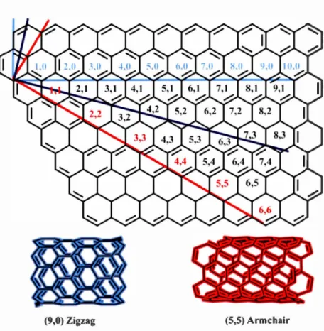
Among ali CNTs, SWNTs have the simplest geometry which can be described with the rolling angle 8. Thus, SWNTs adopt either a zigzag (8 = 0\ an armchair (8 = 30°) or a chiral (0° < 8 < 30°) conformation.(Hersam, 2008; C.-H. Liu & Zhang, 201 0) In arder to classify SWNTs, a pair of integers (n,m) was introduced.(A vouris & Chen, 2006; R B Weisman & Bachilo, 2003) These integers are needed to calculate both the rolling angle, 8, and the tube diameter, d, using equations 1-1 and 1-2, respectively.(Jia Gao, Loi, de Carvalho, & dos Santos, 2011; Luo, Pfefferle, Haller, & Papadimitrakopoulos,
2006) When n=m, the angle reaches a maximum of 30°, corresponding to the armchair
configuration. The lowest angle of
oo
is reached when m = 0, which corresponds to the zigzag configuration. These integers are also significant because they can be used to identify the electronic type ofSWNTs; ifthe result of(n-m) equal3k (k is integer), the nanotube is a metallic, but if the result equals 3k± 1, the nanotube is asemiconducting.(Jia Gao et al., 2011; R. Bruce Weisman, 201 0)
Equation 1-2
(9,0) Zigzag (5,5) Armchair
Figure 1.4: Map of the (n,m) integers indicated on a graphene sheet, and an example
of zigzag and armchair nanotubes.
While metallic SWNTs, m-SWNTs, have a zero band-gap energy, semiconducting SWNTs, sc-SWNTs, have a band-gap energy which is inversely proportional to the nanotube diameter.(Berton et al., 20 Il; Hersam, 2008; Qian et al., 2013; R. Bruce Weisman, 2010; W. Xu et al., 2014) Owing to these interesting electronic properties,
SWNTs have been used in different applications such as in conductive composites,(H. M. Kim et al., 2004; Potschke, Bhattacharyya, & Janke, 2004) or in the development of faster computer processors.(Shulaker et al., 2013) Besides their electronic properties, SWNTs have a Young's modulus as high as 1.2 TPa and a tensile strength as high as 200 GPa(Ma, Siddiqui, Marom, & Kim, 201 0; Vaisman, Wagner, & Marom,
28
2006) and a thermal conductivity of 3500 W /(m · K) at room temperature.(Pop, Mann,
Wang, Goodson, & Dai, 2006)
1.2.1 Synthesis SWNTs
Severa! methods can be used to produce SWNTs (Figure 1.5) such as the arc
discharge,(Ebbesen & Ajayan, 1992; Iijima & Ichihashi, 1993) the laser vaporization (LV),(T. Guo, Nikolaev, Thess, Colbert, & Smalley, 1995; Thess et al., 1996) and the
CVD.(Dai et al., 1996; Endo et al., 1993; W. Z. Li et al., 1996) The arc discharge and
the laser ablation generate tubes with large diameters, typically comprised between 1
and 1.4 nm,(Gomulya, Gaoa, & Loib, 2013) with a higher proportion of the
m-SWNT.(Thess et al., 1996; B. Wang, Wei, et al., 2007) The popular method, CVD
relies on the decomposition of carbon-rich gases over a catalytic substrate. Among the
numerous tubes produced by CVD, let us note the HiPco (high-pressure carbon monoxide) and CoMoCAT (Cobalt Molybdenum Catalyzed) SWNTs.(Kitiyanan,
Alvarez, Harwell, & Resasco, 2000; Nikolaev et al., 1999) While high temperature and
pressure are required for HiPco production, the use of a Co-Mo catalyst supported on
a Si02 substrate enables the preparation of CoMoCA T tubes at lower temperature and
pressure.(Alvarez, Pompeo, Herrera, Balzano, & Resasco, 2002; Kitiyanan et al., 2000;
Resasco et al., 2002) The resulting CoMoCAT tubes have diameters between O. 7 and
1.4 nm, with (6,5) and (7,5) chiralities being predominantly represented.(Sergei M.
Bachilo et al., 2003; Resasco et al., 2002) By contrast, the HiPCO SWNTs have diameters ranging between 0.6 and 1.4 nm and they contain over 50 different (n,m)
chiralities.(S. M. Bachilo, 2002) Both CVD processes predominantly yield sc-SWNTs
(in proportions of -65%).(Nikolaev et al., 1999)
Despite the many improvements in their production processes, ali the SWNTs
produced so far are heterogeneous mixtures oftubes with different diameters, lengths,
chiralities, and electronic types. The influence of operational parameters such as
2006; B. Wang, Wei, et al., 2007) carbon feedstock,(Maruyama, Kojima, Miyauchi, Chiashi, & Kohno, 2002; B. Wang, Poa, et al., 2007) and catalyst pat1icle size and composition (Sergei M. Bachilo et al., 2003; Xiaolin Li et al., 2007; Sinnott et al., 1999) allows to control the diameter of tubes, but no effective method exists to control their chiralities.(Cheung, Kurtz, Park, & Lieber, 2002; Lu & Liu, 2006) Currently, there is
no production method yields SWNTs with acceptable levels of purity and
homogeneity. Consequently, the heterogeneity ofSWNTs strongly cut1ails their use in industry. As a result, the use of a post-treatment is necessary to sort SWNTs.
A B R~.tetion fl~•ling Woater C'hambcr co ils cool cd l.int"ou motion coll Nt or Oullel
-
-
c., Qu.artz lubt' ubslr.ll'e C deposlls Reaction c::h~mbcr fum.an W.lterc
Figure 1.5: A schematic representation of the synthetic methods of SWNTs. (a) Arc discharge, (b) CVD, and (c) laser vaporization. Reproduced from reference.(Gore & Sane, 2011)
1.2.2 Post-treatment of nanotubes
The post-treatments can be categorized into destructive and non-destructive methods. In destructive separation methods, a chemical reaction is employed to separate tubes with the hope that the reaction will be selective for certain species. Thus, the separation will be easier once the tubes are chemically modified. For example, the high electron density near the Fermi leve! in the m-SWNTs lead them to be more chemically reactive