UNIVERSITY OF QUÉBEC AT CHICOUTIMI
A THESIS SUBMITTED TO
THE UNIVERSITY OF QUÉBEC AT CHICOUTIMI IN PARTIAL FULFILMENT OF THE REQUIREMENTS
FOR THE DEGREE OF DOCTOR OF PHILOSOPHY IN ENGINEERING
BY
YADIAN XIE
STUDY ON HIGH-PURITY ALUMINA PREPARATION AND ITS APPLICATIONS
UNIVERSITÉ DU QUÉBEC À CHICOUTIMI
THÈSE PRÉSENTÉE À
L’UNIVERSITÉ DU QUÉBEC À CHICOUTIMI COMME EXIGENCE PARTIELLE
DU DOCTORAT EN INGÉNIERIE
PAR
YADIAN XIE
ÉTUDESURLAPRÉPARATIONDEL’ALUMINEDEHAUTEPURETÉ ETSESAPPLICATIONS
ABSTRACT
Wastewater from different aluminum processing plants contains different surface treatment liquids. These liquids are strictly prohibited from being discharged directly into the environment due to their high acidity. Different factories and enterprises add water to dilute them or neutralize them with alkali. These approaches not only cause a part of the aluminum ions being discharged, but also result in the release of a large number of harmful metal ions and heavy metal ions. In such cases, a large amount of water and alkali are consumed; at the same time, surface water, groundwater and soil become polluted by a large volume of wastewater and different metal ions.
The main objectives of the project are: 1) to extract ultra-pure aluminum ions from wastewater and to study the effect of different parameters on the efficiency of the process; 2) to produce ultra-pure nano-alumina from wastewater using an organic template and to study the effect of different parameters on the particle size distribution as well as on the morphology of the nanoparticles; 3) to explore the possibility of different applications for different types of alumina particles.
In this work, aluminum was extracted from the wastewater in the form of alum. This aluminum alum solution was later used to produce 99.999% pure (5N) nano-alumina particles. Two different methods, namely single and double template methods, were used to control the size and the nature of the alumina particles.
A single template method was used to produce 99.999% pure (5N) spherical alumina nanoparticles. The aluminum alum solution was hydrolyzed to produce boehmite which was used to produce the spherical alumina nanoparticles. Gum arabic and urea were used to produce the single template. These alumina nanoparticles were converted to alpha (α) form by heating. Then, the α-alumina particles were used to produce sapphire crystals.
An evaporation-induced synthesis approach with double template was used to produce spherical mesoporous nanoparticles of uniform size distribution. These particles were used for the photoacoustic tomography.
The originality of the project lies in the utilization of new sources of raw materials (wastewater from industries) and using chelating polymers as well as additives to develop a novel and environment friendly high purity alumina (HPA) production method. In addition, the alumina particle size and its distribution are controlled precisely, which is difficult to achieve with other alumina production methods.
RÉSUMÉ
Les eaux usées provenant des différentes usines de traitement de l'aluminium contiennent de différents liquides de traitement de surface. Ces liquides sont strictement interdits d'être déchargés directement à l'environnement en raison de leur forte acidité. Des différentes usines et entreprises ajoutent de l'eau pour les diluer ou les neutralisent avec l'alcali. Ces traitements provoquent non seulement la décharge d'une partie des ions d'aluminium, mais également la libération d'un grand nombre d'ions métalliques nocifs et d'ions de métaux lourds. Dans ces cas, des grandes quantités de l'eau et de l'alcali sont consommées; en même temps, les eaux de surface, les eaux souterraines et le sol sont pollués par un grand volume d'eaux usées et de différents ions métalliques.
Les objectifs principaux du projet sont : 1) d'extraire les ions d’aluminium ultra-purs des eaux usées et d'étudier l'effet de différents paramètres sur l'efficacité du procédé; 2) de produire la nano-alumine ultra-pure à partir des eaux usées en utilisant un modèle organique et d’étudier l'effet de différents paramètres sur la distribution granulométrique et la morphologie des nanoparticules; 3) d’explorer différentes applications des différents types des particules d'alumine.
Dans ce travail, l'aluminium a été extrait des eaux usées sous forme d'alun en utilisant un modèle simple. Cette solution d'alun a ensuite été utilisée pour produire des particules de nano-alumine pur à 99,999% (5N). La solution d'alun a été hydrolysée pour produire une bohémite qui a également été utilisée pour produire des nanoparticules d’alumine sphérique
pure à 99,999% (5N). Ces microparticules d'alumine ont été utilisées pour produire des cristaux de saphir.
Une approche basée sur la séparation induite par évaporation à double modèle a été utilisée pour produire des nanoparticules mésoporeuses sphériques avec une distribution de taille uniforme. Ces particules ont été utilisées pour la tomographie photoacoustique.
L’originalité du projet est l’utilisation de nouvelles sources des matières premières (l’eau usée des industries) et des polymères chélatants et des additives afin de développer une nouvelle méthode écologique pour la production de l’alumine de haute pureté. De plus, la taille des particules de l’alumine et sa granulométrie sont contrôlées précisément, ce qui est difficile à atteindre avec d’autres méthodes de la production de l’alumine.
ACKNOWLEDGEMENTS
This research would not have been possible without the guidance of my thesis director, Prof. Duygu Kocaefe, co-director Prof. Yasar Kocaefe, and Prof. Wei Liu. I would like to express my deepest respect and gratitude for their scientific guidance, their trust and support all along the path.
Many thanks to Prof. Dipankar Bhattacharyay for his insight, scientific discussions, and time. I especially thank Mr. Pascal Vandal, Mr. Patrice Paquette, and Mr. Dany Racine in Canada, and Mr. Lei Li, Mr. Gonglei Zhang, and Mr. Xin Nie in China for their assistance with the equipment handling, sample preparation, and data analysis.
Thanks also to all my friends I met in Chicoutimi for their encouragement and support. I would like to express my warm wishes to my parents and my whole family for their unending love and trust throughout my education. Finally, this thesis is dedicated to Yuanyuan Sun and Maple Xie for putting up with me and standing by my side all the time.
This research was supported by the University Research Centre on Aluminum (CURAL) of the University of Québec at Chicoutimi (UQAC), the Guizhou Normal University (GNU), and HTOT Optoelectronics Technology Cooperation and National Centre for Nano-Science and Technology.
TABLE OF CONTENTS
ABSTRACT ... i RÉSUMÉ ... iii ACKNOWLEDGEMENTS ... v TABLE OF CONTENTS ... vi LIST OF FIGURES ... ixLIST OF TABLES ... xiii
LIST OF APPENDICES ... xiv
Chapter 1 ... 1
Introduction ... 1
1.1 Background ... 1
1.2 Statement of the Problem ... 5
1.3 Objectives ... 6 1.4 Originality ... 7 1.5 Methodology ... 8 1.6 Scope ... 9 Chapter 2 ... 11 Literature review ... 11 2.1 Hydrothermal methods ... 12 2.2 Sol-gel method ... 16 2.3 Template method ... 19 2.3.1 Hard template ... 21 2.3.2 Soft template ... 29
2.3.3 Comparison of hard and soft template ... 34
2.4 The effect of calcination system on the morphology of alumina ... 35
2.5 Summary ... 38
Chapter 3 ... 40
Methodology ... 40
3.1 Experimental ... 40
3.1.2 Treatment of the reagents and improvement of the purity ... 44
3.1.3 Preparation of high purity alum solution from the wastewater ... 44
3.1.4 Production of 5N (99.999% pure) spherical alumina nanoparticles by single templating.………45
3.1.5 Production of 5N (99.999% pure) spherical mesoporous alumina nanoparticles by double templating ... 45
3.1.6 Application of the 5N alumina nanoparticles in different fields ... 46
3.1.6.1 Preparation of sapphire crystal ... 46
3.1.6.2 Photoacoustic (PA) tomography ... 48
3.2 Characterization of alumina samples ... 49
Chapter 4 ... 50
Preparation of high purity alum solution from the wastewater ... 51
4.1 Introduction ... 51
4.2 Results & Discussion ... 52
4.2.1 Characterization of the wastewater ... 52
4.2.2 Treatment of the reagents and improvement of the purity ... 53
4.2.3 Purification of H2SO4 ... 54
4.2.4 Preparation of high purity alum solution from the wastewater ... 55
Chapter 5 ... 63
Production of 5N (99.999% pure) spherical alumina nanoparticles by single templating .. 63
5.1 Introduction ... 63
5.2 Production of 5N (99.999% pure) spherical alumina nanoparticles by single templating.………63
5.3 Results ... 65
5.3.1 The Effect of Synthesis Conditions on Spherical Alumina Morphology 65 5.3.2 The Effect of Gum Arabic (GA)/Urea Weight Ratio on Spherical Alumina Morphology ... 69
Chapter 6 ... 72
Production of 5N (99.999% pure) spherical mesoporous alumina nanoparticles by double templating ... 72
6.1 Introduction ... 72
6.2 Production of 5N (99.999% pure) spherical mesoporous alumina nanoparticles by double templating: ... 73
6.3 Results ... 75 6.3.1 The effect of synthesis temperature and time on the morphology of
6.3.2 The Effect of GA/P123 Weight Ratio on of Spherical Morphology ... 79
6.3.3 Spherical Mesoporous Alumina ... 82
Chapter 7 ... 85
Advanced applications of the 5N alumina nanoparticles in different fields ... 85
7.1 Introduction ... 85
7.2 Preparation of alumina particles as a precursor for sapphire crystal growth ... 86
7.3 Application of Spherical Alumina on Sapphire Growth Using the Heat Exchange Method…...….……….87
7.4 Photoacoustic (PA) tomography ... 91
Chapter 8 ... 94
Conclusions and Recommendations ... 94
8.1 Conclusions ... 94 8.2 Recommendations ... 96 REFERENCES ... 97 PUBLICATIONS ... 112 APPENDIX I ... 113 APPENDIX II ... 124
APPENDIX III : Patent 1 ... 134
LIST OF FIGURES
Page
Figure 2.1 Phase transformation of alumina 11
Figure 2.2 TEM image of alumina prepared under different temperatures. (a) 90ºC, (b) 120ºC, (c) 150ºC
14
Figure 2.3 TEM images of nano-alumina with sodium nitrate concentration of (a) 0 mol, (b) 0.2 mol, (c) 0.4 mol, (d) 0.6 mol
15
Figure 2.4 TEM images of α-Al2O3. (a) needle-like α-Al2O3, (b) plate-like
α-Al2O3
15
Figure 2.5 TEM images of γ-AlOOH prepared at (a) pH=5, (b) pH=7, (c) pH=9
16
Figure 2.6 TEM images of alumina nanoparticles with different amount of AcOH. (a) No AcOH, (b) m(AcOH)/m[Al(Opri)3]<0.05,
(c) m(AcOH)/m[Al(Opri)3]≈0.1
17
Figure 2.7 SEM images of alumina particles with different molar ratio of [Bmim] PF6 and aluminum isopropoxide. (a) Al2O3-0, (b)
Al2O3-0.03, (c) Al2O3-0.12, (d) Al2O3-0.18, (e) Al2O3-0.24, (f)
Al2O3-0.30
18
Figure 2.8 AAO Structure 22
Figure 2.9 TEM images of productions fabricated by AAO template. (a) ZnS nanowires, (b) rod-like silica
23
Figure 2.10 Synthesis of gold nanowires using porous aluminum oxide membrane template
24
Figure 2.11 TEM images of mesoporous carbon structure (a) top view, (b) side view
25
Figure 2.12 TEM images of particles prepared by CMKs-template (a) hexagonal mesoporous MgO, (b) RMM-1 with cubic crystal system, (c) RMM-3 with the hexagonal crystal system
26
prepared by PSA (a) PSA, (b) PSA/ZnS/CdS, (c) ZnS/CdS
Figure 2.14 Structure of liquid crystals 30
Figure 2.15 TEM images of mesoporous silica (a) silica microsphere, (b) mesoporous silica thin film
31
Figure 2.16 TEM images of cuprous oxide crystals (a) lamellar cuprous oxide crystal, (b) urchin-like cuprous oxide crystal, (c) acicular cuprous oxide crystal
32
Figure 2.17 Mechanism of soft template method 34
Figure 2.18 The relationship between temperature and phase transformation of alumina
36
Figure 3.1 Schematic of the methodology 41
Figure 3.2 Change in color during titration by ZnCl2 solution 43
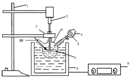
Figure 3.3 Laboratory scale experimental system to obtain high purity alum solution from wastewater
45
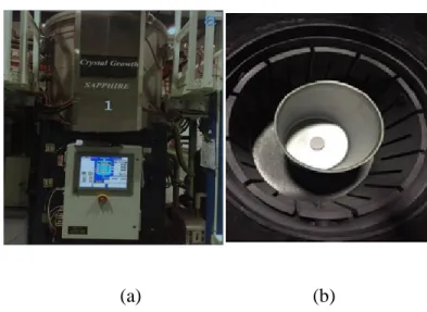
Figure 3.4 Heat exchange method crystal growth equipment (a) outside view of the crystal growth furnace, (b) inside view of the crystal furnace
48
Figure 4.1 Comparison of the HPA purity and cycles of recrystallization by adding different additives
57
Figure 4.2 Total removal efficiency as a function of reaction time 60 Figure 4.3 Total removal efficiency as a function of temperature 61 Figure 5.1 XRD patterns for the precursor under different synthesis
conditions (A) Amorphous-120°C-3h; (B) Amorphous (140°C-3h); (C)AlO(OH) (160°C-(140°C-3h); (D) AlO(OH) (180°C-(140°C-3h); (E) AlO(OH) (140°C-9h); (F) AlO(OH) (140°C-15h)
66
Figure 5.2 XRD patterns for spherical alumina under different synthesis conditions at 600°C (A) Al2O3 (120°C-3h); (B) Al2O3
(140°C-3h); (C) Al2O3 (160°C-3h); (D) Al2O3 (180°C-3h); (E) Al2O3
(140°C-9h); (F) Al2O3 (140°C-15h)
67
Figure 5.3 SEM images of spherical alumina samples (heated at 600ºC) under different synthesis conditions (a) Al2O3 (120°C-3h);
(b) Al2O3 (140°C-3h); (c) Al2O3 (160°C-3h); (d) Al2O3
(180°C-3h); (e) Al2O3 (140°C-9h); (f) Al2O3 (140°C-15h)
Figure 5.4 The SEM images of intermediate Al2O3 (calcined at 600ºC)
prepared according to different GA/urea weight ratios (a) Al2O3-0; (b) Al2O3-0.625; (c) Al2O3-1.25; (d) Al2O3-2.5
70
Figure 6.1 Precursor XRD patterns under different synthesis conditions (I) Amorphous (120°C-3h), (II) Amorphous (140°C-3h), (III) AlO(OH) (160°C-3h), (IV) AlO(OH) (180°C-3h), (V) AlO(OH) (140°C-9h), (VI) AlO(OH) (140°C-15h)
76
Figure 6.2 Mesoporous Alumina XRD patterns under different synthesis conditions after calcination at 600°C (I) Al2O3(120°C-3h), (II)
Al2O3 (140°C-3h), (III) Al2O3 (160°C-3h), (IV) Al2O3
(180°C-3h), (V) Al2O3 (140°C-9h), (VI) Al2O3 (140°C-15h)
77
Figure 6.3 SEM images of mesoporous alumina samples (calcined at 600ºC) prepared under different synthesis conditions; (a) Al2O3
(120°C-3 h); (b) Al2O3 (140°C-3 h); (c) Al2O3 (160°C-3 h); (d)
Al2O3 (180°C-3 h); (e) Al2O3 (140°C-9 h); (f) Al2O3
(140°C-15 h)
78
Figure 6.4 Pore size distributions and corresponding SEM images of the alumina particles (samples VII-XI) with different GA/P123 weight ratios
81
Figure 6.5 TEM images of the spherical mesoporous alumina materials 82 Figure 6.6 Nitrogen sorption isotherms and corresponding pore size
distributions of the spherical mesoporous alumina materials
83 Figure 7.1 XRD patterns of alumina used as sapphire crystal raw material
under different synthesis conditions after calcination at 1800°C (A) Al2O3-120°C-3h, (B) Al2O3-140°C-3h, (C) Al2O3
-160°C-3h, (D) Al2O3-180°C-3h, (E) Al2O3-140°C-9h, (F) Al2O3
-140°C-15h
87
Figure 7.2 Relationship between the intermediate Al2O3 with different
shapes and the total length of sapphire crystal rods
89
Figure 7.3 (a) Sapphire crystal (115 kg,diameter=380 mm, height=245 mm), (b) Sapphire crystal rods (Φ34), (c) Sapphire wafers (2 inches)
89
Figure 7.5 Sapphire c-plane (0001) wafer transmission spectrum 91 Figure 7.6 Schematic illustration of pharmacokinetic and biodistribution
analysis of chitosan-capped gold nanoparticles by MSOT
92 Figure 7.7 TEM and SEM images of AuNS and AuNR particles 92 Figure 7.8 TEM micrograph of modified alumina nanoparticles doped with
gold nanoparticles
LIST OF TABLES
Page
Table 4.1 Impurity content of the wastewater 52
Table 4.2 The trace element content of additives before treatment 53 Table 4.3 Comparison of removal efficiency of diluted sulfuric acid
solutions
54
Table 4.4 The trace element content of additives after treatment 54 Table 4.5 Total removal efficiency of the first crystallization 55 Table 4.6 Total removal efficiency of the second crystallization 56 Table 4.7 Total removal efficiency of the third crystallization 56 Table 4.8 Relation between PX-17 amount and total removal efficiency 58 Table 4.9 Relation between SX-1 amount and total removal efficiency 58 Table 4.10 Relation between molecular sieve 13X amount and total
removal efficiency
59
Table 5.1 Process parameters for alumina prepared under different conditions
64
Table 5.2 Morphology of alumina (calcined at 600ºC) with different GA/urea weight ratios
69
Table 6.1 Textural properties of mesoporous alumina with different GA/P123 weight ratio
79
LIST OF APPENDICES
Appendix Title Page
I The effect of novel synthetic methods and parameters to control morphology of nano-alumina particles
113
II In vivo pharmacokinetic features and biodistribution of star and rod shaped gold nanoparticles by multispectral optoacoustic tomography
124
Chapter 1
Introduction
1.1 Background
The surface of different products made of aluminum and aluminum alloys is treated to improve appearance, durability, and adhesion properties. The surface treatment includes numerous physical and chemical processes. Physical surface treatments produce solid wastes and oil-bound suspensions. The chemical treatment results in large volumes of wastewater with high acidity. These liquids are strictly prohibited from being discharged directly into the environment. Different factories and enterprises add water to dilute them or neutralize them with alkali. These treatments result in the release of a large number of harmful metal ions and heavy metal ions. Thus, large amounts of water and alkali are consumed, at the same time, surface water, groundwater, and soil get polluted by a large volume of wastewater and different metal ions.
Shi and Xia [1] extracted aluminum ion (Al3+) from aluminum foil treatment wastewater to prepare polyaluminum chloride (PAC), which can be used in other wastewater treatment plants as flocculants. However, he could not address the issue of the presence of other metal cations such as calcium, iron, copper, sodium or even heavy metal cations. These impurities continue to exist in the flocculants and may cause secondary pollution.
In recent years, different methods have been developed to convert aluminum ion (Al3+) in wastewater to a number of industrial products such as aluminum sulfate, aluminum carbonate, and polymeric ferric aluminum chloride. The intention is to do a resourceful recycling of the wastewater. The problem with these methods is that the products are mostly of low quality, and they are low value-added products. These products cannot be self-sufficient enough to support the cost of wastewater treatment; therefore, the recycling of wastewater cannot be effective and stable [2].
Some researchers proposed to treat wastewater by using ion exchange method such as the use of ion exchange resin for the recovery of aluminum ion (Al3+). This method can partially remove the metal ions due the preferential adsorption of different ions by the ion exchange resin, but cannot completely purify the wastewater. Especially, the long adsorption time, unstable adsorption amounts, and the cost of ion exchange resin makes this choice economically unviable for the factories and the enterprises [3-6].
Ultra-high purity nano-alumina is a value-added product and has the advantages of high density, high melting point, high hardness, and good chemical stability. It is widely used in a variety of optical devices, window materials, and sapphire substrate materials in modern high-tech industries. Alumina powder is conventionally produced from the bauxite ore by the Bayer process. This process is simple, but requires extensive processing and consumes large amounts of energy. The purity of the alumina produced is around 98% - 99%. The particle size is usually bigger than 10 μm, and the particle size distribution is not uniform. Thus, the alumina produced by the Bayer process is mainly used for the
electrolytic production of primary aluminum. Based on the Bayer process, many methods have been developed. These methods include ammonium aluminum sulfate (aluminum alum), aluminum alkoxide, and flame sintering at high temperature. These methods require costly raw materials. The ammonium aluminum sulfate method needs high purity aluminum hydroxide; aluminum alkoxide method requires high purity aluminum block; high temperature sintering method utilizes high purity aluminum powder. At the same time, large amounts of harmful gases such as nitrogen oxides, sulfur monoxide, sulfur dioxide, hydrogen sulfide, and isopropanol, are released during the heat treatment of different chemicals. These methods generally have high raw material cost and can cause environmental pollution. Also, it is difficult to control the size of the alumina particles.
Alumina can be used in different high value-added products such as adsorbents [7], ceramics [8], catalysts and catalyst carriers [9], etc. These applications depend not only on the particle size, but also on the particle shape. Presently, the common shapes of aluminum oxide can be rod-like [10], fibrous [11], plate-like [12], spherical [13], etc. Seyed et al. [14] have successfully prepared γ-aluminum from kaolinite by the precipitation method combined with sulfuric acid leaching, and high temperature calcination. The alumina particles were large and the morphology was irregular. The particle sizes were between 0.5 μm and 0.9 μm. Dabbagh et al. [15] and Feng et al. [16] prepared rod-like, fibrous, and spherical alumina particles by using a single template method and separating nucleation and aging steps (SNAS). The morphology of the alumina particles was mostly irregular. The dispersibility of the alumina particles were poor, the processes were complex, costly, and hard to control. Lv et al. [17] prepared spherical alumina with high thermal stability,
high sphericity, and uniform particle size distribution by dropping a boehmite sol in an oil-ammonia column. The boehmite sol was the source of aluminum. However, the particle size of the prepared product was large, which limits its application area. Wu et al. [18] used aluminum isopropoxide precursor and polyethylene glycol - polypropelene glycol - polyethylene glycol (P123) block-copolymer template and synthesized organized mesoporous alumina with hierarchical structure.
Mesoporous materials have the characteristics of high specific surface area, organized pore structure, narrow pore size distribution, and continuous pore size; therefore, they play an important role in adsorption and separation, especially in catalytic reactions [19]. The spherical alumina has high fluidity, which means it does not easily agglomerate, and will enhance the catalytic activity [20]. The nano-scale spherical mesoporous alumina can improve its application in adsorption, separation and catalytic reactions.
Another important application of alumina is the production of sapphire crystals. Advances are made in the development of sapphire crystals in recent years because of its excellent optical, chemical, and other properties. It is the most common LED (Light-Emitting Diode) substrate material. In the global market of LED substrate, two-inch sapphire wafers are widely used. The heat exchange method is a crystal growth technique used for the production of large sapphires. In 1970, Schmid and Viechnicki [21] first grew sapphire crystals using the heat exchange method. A heat exchanger was used to remove heat, causing a longitudinal temperature gradient that is cold at the bottom and warm at the top of the crystal growth area. The temperature gradient was controlled by regulating the
rate of gas flow in the heat exchanger (helium gas) as well as the heating power. The pressed alumina blocks were melted in a crucible at around 2100 ºC, and the sapphire crystals were slowly solidified by cooling with a flow of helium gas. The heat exchange method requires high-quality raw materials in order to have a stable temperature field during the crystal growth process. The segregation coefficient of the impurities in the melted crystal is set to less than 1. Impurities are therefore continuously discharged into the melted crystal from the solid-liquid interface and distributed to the outer layer of the surface where the crystals and the crucible wall come in contact [22-25].
In this work, aluminum has been extracted from the wastewater in the form of aluminum alum (in the rest of the text, alum refers to the aluminum alum). This alum solution was later used to produce 99.999% pure (5N) nano-alumina particles. The alum solution was hydrolyzed to produce boehmite which was also used to produce 99.999% pure (5N) spherical alumina nanoparticles by the single template method. These alumina nanoparticles were used to produce sapphire crystal.
An evaporation-induced synthesis approach with double template was used to produce the spherical mesoporous nanoparticles of uniform size distribution. These particles were used for the photoacoustic tomography.
1.2 Statement of the Problem
It is important for the industry to develop methods to extract high purity alumina from wastewater produced by the chemical treatment of aluminum surfaces. The chemical
surface treatment methods conventionally used in the aluminum industry include chemical etching, electrochemical etching, chemical milling, dyeing, anodizing, etc. In these processes, large amounts of acids (such as sulfuric acid) are used. These surface treatment methods produce large volumes of wastewater with low pH. This type of wastewater also contains different metal ions. Depending on the purity and particle size, the alumina particles can be used in different fields. It is important to have a small average alumina particle size and a narrow particle size distribution in the range of 20 to 200 nm in order to control the quality (homogeneity) of the final product. It is necessary to explore different applications of alumina particles. The industry needs to find value-added products as well as novel applications which can increase the return and reduce environmental pollution.
1.3 Objectives
The main objectives of this study are:
1. to extract ultra-pure aluminum ions from wastewater and to study the effect of different parameters on the efficiency of the process.
2. to produce ultra-pure nano-alumina from wastewater using an organic template and to study the effect of different parameters on the particle size distribution and the morphology of nanoparticles.
1.4 Originality
1. Considering the increasing demand of high purity alumina (HPA) and the high cost, the novelty of this project is to test new sources of raw materials (wastewater from industries) and to develop a novel HPA production process. Nowadays, high purity raw materials are used to produce HPA. This project valorizes a wastewater effluent and not much research has taken place on the use of wastewater as raw material for HPA.
2. Most of the existing HPA production processes (such as the Bayer process, the use of alum, etc.) are not environment-friendly because of the emissions of harmful gases and wastes. The novelty of the current project lies in the production of good quality HPA from industrial wastes in an environment-friendly way.
3. Use of chelating polymers and additives has not been studied in detail in the production of HPA. Chelating compounds were used to reduce the trace element content in HPA during this study.
4. Presently, the commercial methods do not have enough control on the size distribution of HPA produced. In this project, methods were developed to produce not only HPA, but also to control the particle size and its distribution. The effect of pH, dilution of raw materials, rate of addition of reagents, heating conditions, etc. on the quality of HPA has not yet been studied systematically.
1.5 Methodology
Different wastewater samples were analyzed for aluminum and other metal ions and anions by ICP-OES, titration and liquid chromatography. The reagents used in this work were treated to improve their purity. The wastewater was treated with different chelate compounds under controlled pH conditions to remove different impurities. The effect of different parameters on the removal efficiency of the reagents was studied. Then, aluminum was extracted from the wastewater in the form of alum via the treatment with ammonia and sulfuric acid. This alum solution was later used to produce 99.999% pure (5N) nano-alumina particles. Two different methods, namely single and double template methods, were used to control the size and the nature of the alumina particles.
A single template method (using gum arabic and urea) was used to produce 99.999% pure (5N) spherical alumina nanoparticles. The template was removed by heating at 600ºC. These alumina nanoparticles were converted to alpha (α) form by heating at high temperature (1800ºC). Then, α-alumina particles were used to produce sapphire crystals.
An evaporation-induced synthesis approach with double template (using gum arabic, P-123, and urea) was used to produce spherical mesoporous nanoparticles with uniform size distribution. The particles were heated to 600ºC to remove the template. These particles were used for photoacoustic tomography.
1.6 Scope
In this thesis, the production of ultra-pure nano-alumina particles from wastewater has been studied. Two different methods, namely single and double template methods, have been used to synthesize nano-alumina particles. These nanoparticles were calcined at different temperatures and used in sapphire production and photoacoustic tomography. This thesis contains seven chapters.
Chapter 1 is the introduction. It presents the background, statement of the problem, objectives, originality, general methodology and the scope of the thesis.
Chapter 2 gives a comprehensive literature review which focuses on different methods of nanoparticle synthesis.
Chapter 3 describes the methodology. This includes the characterization of wastewater and the treatment of reagents. This chapter also describes the application of the treated reagents to prepare high purity alum from wastewater. The alum solution was used to prepare nano-alumina particles which were finally used for sapphire production and photoacoustic tomography.
Chapter 4 describes the results related to the preparation of high purity alum solution from wastewater. This chapter also includes the treatment and the characterization of the reagents to identify the conditions suitable for the purification of reagents.
Chapter 5 gives a detailed description of the production of 5N (99.999% pure) spherical alumina nanoparticles by single templating. The results of the characterization of nanoparticles and the effect of different parameters on nanoparticles have been presented.
Chapter 6 describes the production of 5N (99.999% pure) spherical mesoporous alumina nanoparticles by double templating. The results of the characterization of mesoporous nanoparticles and the effect of different parameters on the nanoparticles have been presented.
Chapter 7 presents the advanced application of 5N alumina nanoparticles in different fields. It includes the use of spherical alumina for sapphire growth using the heat exchange method and the application of mesoporous alumina nanoparticles in the photoacoustic tomography.
Conclusions and recommendations of the work are given in Chapter 8. This is followed by a list of references and three appendices which present published articles and patents.
Chapter 2
Literature review
Different materials are essential for the social development. Generally, certain material structure and morphology are required for their applications in a specific field. Inorganic materials are an important branch of materials, which promote development of science and technology. Alumina is an inexpensive and widely used inorganic material. It has a complex structure and many crystalline polymorphic phases such as α-Al2O3, β-Al2O3,
γ-Al2O3, δ-Al2O3, θ-Al2O3, η-Al2O3, κ-Al2O3, χ-Al2O3, ρ-Al2O3, etc. The phase transition
temperatures are different for different precursors during their calcination as shown in Figure 2.1 [26].
Figure 2.1: Phase transformation of alumina
The morphology, purity, surface acidity and hydrothermal stability, the pore structure and other properties restrict the application of alumina. The research is ongoing on the pore structure, surface acidity and hydrothermal stability [27]. Morphology, as one of the
important parameters of particle characterization, has a substantial effect on the properties and applications of the products. The morphology of particles is influenced and controlled by its crystallization habit during the preparation using liquid phase method [28, 29], which is restricted by the environment and the growth conditions.
There are some common liquid phase methods for synthesis of alumina, such as sol-gel method, hydrothermal method, template method, precipitation method, emulsion method or microemulsion method and electrolysis method, etc. Alumina with different morphologies can be obtained by using different synthesis methods and optimizing the reaction conditions.
2.1 Hydrothermal methods
Hydrothermal method is an approach where a solution of different species is poured into a sealed reactor and treated to produce a single crystal. Utilization of the relatively high temperature in the reactor and the high-pressure growth environment promotes the dissolution and recrystallization of poorly soluble or insoluble material. Hydrothermal methods include hydrothermal synthesis, hydrothermal treatment, hydrothermal reactions, etc. During the hydrothermal process, the crystal grows to its largest possible size under the non-restricted conditions and its characteristics (various shapes, high degree of crystallinity, small size, uniform distribution, less particle agglomeration, etc.) form [30, 31]. The development of crystal face and the morphology of the crystal formed by hydrothermal synthesis are closely related to the hydrothermal conditions such as water temperature, pressure and the permittivity, viscosity and diffusion coefficient of the solution, etc. The
same type of crystal can be produced with different morphology under different hydrothermal conditions [32].
Li et al. [33] mixed ammonium aluminum sulfate, dispersant PEG2000 and urea in deionized (DI) water and stirred them vigorously to form a solution. Then, the solution was poured into a stainless steel pressure reactor with a Teflon lining. By changing the temperature of the water, mesoporous alumina with different morphologies were obtained. In the course of the reaction, following reactions take place:
CO(NH2)2 + H2O CO2 + 2NH3 (1)
NH3 + H2O NH4 + OH- (2)
Al3+ + 3OH- AlO(OH) + H2O (3)
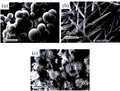
As Figure 2.2 (a) shows, when the temperature is 90ºC, the particles obtained are spheres of different sizes. As it is shown in Figure 2.2 (b), at the temperature of 120ºC, the particles are superfine shaped. As Figure 2.2 (c) shows, massive fiber-shaped particles are obtained at the temperature of 150ºC. The crystal orientation is dependent on the temperature which affects the growth rate of the crystal face, consequently, the morphology can be controlled by regulating the temperature. These results indicate that the morphology of the particles substantially changes with the increasing water temperature.
Figure 2.2: TEM images of alumina prepared under different temperatures. (a) 90ºC, (b) 120ºC, (c) 150ºC [34]
Zhao et al. [34] prepared flat hexagonal-shaped nano-alumina by hydrothermal synthesis, using aluminum nitrate as aluminum source and sodium nitrate as additive. During the reaction, the Na+ of sodium nitrate was adsorbed onto the alumina surface, which hindered the accumulation of Al3+ and OH- ions. This affected the appearance of the particles. By changing the amount of sodium nitrate additive to control the growth of certain crystal face of alumina, hexagon-shaped alumina with different parameters was obtained. When the amount of sodium nitrate was 0.2 mol, the width of the particle was reduced and its length and thickness remained unchanged. When sodium nitrite was 0.4 mol and 0.6 mol, the thickness increased and the length and width remained unchanged. The hexagon-shaped particles were gradually transformed into thicker particles as the sodium nitrate concentration increased as shown in Figure 2.3.
Figure 2.3: TEM images of nano-alumina with sodium nitrate concentration of (a) 0 mol, (b) 0.2 mol, (c) 0.4 mol, (d) 0.6 mol. [35]
Depending on different reaction systems, particles have accordingly different crystal habits. Pramod et al. and Shi et al. [36] synthesized needle-like and plate-like α-Al2O3, respectively, in water and alcohol-water reaction systems by hydrothermal
treatment method using Al(OH)3 colloid as precursor, as shown in Figure 2.4.
Mikhailov et al. [38] prepared hexagonal flake-shaped γ-Al2O3 by hydrothermal
method with Al2(SO4)3⋅18H2O and ammonia as raw materials. This study has shown that
pH of solution has a significant impact on the morphology of precursor. Under acidic conditions, the H+ in solution binds with the hydroxyl group, which is on the surface of the γ-AlO(OH) layered structure, thereby destroys this structure, eventually forms a rod-like nanostructure by rolling growth mechanism [39]. On the contrary, under alkaline conditions, it retains its layered structure, forming plate-shaped nanostructure. Figure 2.5 shows that when pH is 5, the product is like; when pH is 7, the product is transformed from rod-like to plate-shaped nanostructure; when pH is 9, the product has hexagonal shape. Boehmite converts into a γ-Al2O3 during the firing process, but its shape and size do not
change. Calcining the plate-like precursor at 600ºC for 4 hours, resulted in the original hexagonal γ-Al2O3 with basically same size.
Figure 2.5: TEM images of γ-AlO(OH) prepared at (a) pH=5, (b) pH=7, (c) pH=9 [40-41]
2.2 Sol-gel method
The sol-gel method refers to inorganic or organic alkoxide dispersed in solution. Using the transparent sol formed by hydrolysis and condensation of the precursor, a gel with
certain structure is formed during the aging process by the aggregation of the gel particles. During the sol-gel process, the microstructure of the material is controlled and cut at the mesoscopic level by means of low temperature chemical method, which changes the morphology and structure of the particles [42, 43].
Ning et al. [44] using acetic acid (AcOH) as additive and adopting two-step alkoxide hydrolysis sol-gel method, synthesized spherical and fibrillar Al2O3 nano powder in organic
phase. The results showed that the amount of AcOH has a decisive effect on the morphology of the particles. As the amount of AcOH increased with respect to aluminum isopropoxide [Al(Opri)3], the shape of the particles gradually shifted from the fibrillar to
the spherical shape, as shown in Figure 2.6. During the reaction, AcOH and other organic molecules containing functional groups N, O, S (ethylacetoacetate, polyamide, carboxylic acid salt) as additives coordinate with inorganic ion or are adsorbed onto the surface of crystal nucleus, which changes the growth rate of crystal face. This leads to the change in morphology of particles.
Figure 2.6: TEM images of alumina nanoparticles with different amount of AcOH (a) No AcOH, (b) m(AcOH)/m[Al(Opri)3]<0.05, (c) m(AcOH)/m[Al(Opri)3]≈0.1 [44]
Figure 2.7: SEM images of alumina particles with different molar ratio of [Bmim] PF6 and
aluminum isopropoxide (a) Al2O3-0, (b) Al2O3-0.03, (c) Al2O3-0.12, (d) Al2O3-0.18,
(e) Al2O3-0.24, (f) Al2O3-0.30 [45, 46]
Masouleh et al. and Ji et al. [45. 46] using aluminum isopropoxide [Al(Opri)3] as
aluminum source, [Bmim] PF6 (1-Butyl-3-methylimidazolium hexafluorophosphate) as ionic liquid and adopting sol-gel method to change the molar ratio of [Bmim] PF6 and aluminum isopropoxide, successfully synthesized uniform rod-like mesoporous γ-Al2O3. This study has shown that ionic liquid plays a very important role in the
morphology of products. As it is shown in Figure 2.7, with the molar ratio of [Bmim] PF6, aluminum isopropoxide increases from 0 to 0.18, the morphology of the products has a highly homogeneous rod shape. When the molar ratio of [Bmim] PF6 and aluminum isopropoxide is 0.18, the morphology of the products with rod shape has the best homogeneity. If this ratio exceeds 0.18, it is not conducive enough to form the rod shape.
2.3 Template method
Template synthesis of nanomaterials is a cutting-edge technology developed since 1990s. It is also a very effective nanomaterials synthesis method that has been widely used in recent years. Early in 1999, South Korean scientists Kim et al. [47] took MCM-48 mesoporous silica as template and synthesized three-dimensional cubic mesoporous carbon CMK-1. In the same year, Japanese scientists Moriguchi et al. [48] used a cationic surfactant CTAB as template and synthesized disordered carbon materials by using phenolic resin as carbon source. Template method is not sensitive regarding the preparation conditions, easy to operate and implement, which controls the structure, morphology and particle size of nanomaterials through the template material (template). Template method is often divided into hard and soft template methods. Dong et al. [49] from Fudan University adopted hard template method. Through using mesoporous carbon pellets as a template, they have synthesized a variety of non-silicon-based mesoporous materials such as solid or hollow aluminum oxide, titanium oxide and aluminum phosphate microspheres. Firouzi et
al. [50] and Huo et al. [51] from University of California used soft template method to
explore a variety of different types of inorganic and organic combinations and proposed the general synthetic route to mesoporous materials.
Morphology is an important parameter for characterization of material properties, especially in the mesoporous material. Morphology, together with particle size, surface area, pore structure determines the property of mesoporous materials, consequently, pinpoints their applications [52, 53]. Among these, mesoporous thin films, as film-like material, have
an unparalleled advantage in adsorption and separation compared to the other nanomaterials with different shapes [54, 55].
The template method changes the morphology of products, mainly, by controlling the crystal nucleation and growth during nanomaterial preparation. Route of nanomaterial synthesis by using the template method is generally divided into three steps: First, the template is prepared. Second, some common synthetic approach such as hydrothermal method, precipitation and sol-gel method is used to synthesize the target product using the template. Finally, third step is the template removal. The choice of template for nanomaterial preparation is critical. Templates usually can be grouped in two major categories: natural substances (nanomineral, biological molecules, cells and tissues, etc.) and synthetic materials (surface active agents, porous materials and nanoparticles, etc.). In addition, the templates are generally divided into two groups (hard template and soft template) based on the difference in the template structure [56, 57].
Template removal is the last step in the synthesis of nanomaterials. The appropriate method of removal has to be chosen such that the physical and chemical properties of the product should not be affected. Common removal methods include physical and chemical methods, such as dissolution, sintering, etching, etc. The morphology of the nanomaterials can be controlled using different hard and soft templates.
2.3.1 Hard template
Hard template is a rigid material, whose stable structure directly determines the size and morphology of sample particle. A wide choice of hard templates is available, such as polymer microspheres, porous membrane, plastic foam, ion exchange resin, carbon fiber and porous anodic aluminum oxide (AAO), etc. [58, 59]. Because of their special structures and effect on particle size restriction, they play an important role in many fields.
a) Porous anodic aluminum oxide (AAO)
Porous anodic alumina has high pore density. The pores are evenly distributed and very thin. The pore size is adjustable in range of 50-200 nm and the pore density is between 1 × 10⁹ and 1 × 1012 cm-2 [60, 61]. It is widely used in the preparation of nano functional devices. For example, it is used in the deposition of metal, semiconductor, conductive polymer and other functional materials and has been successfully applied in fields of magnetic recording materials, optoelectronic components, electronics, etc. [62-69].
The preparation process of AAO has not been unified. Usually the high purity aluminum piece is placed into an acidic solution, and AAO is obtained by electrolysis by the anodic oxidation. By changing anode voltage and the composition, and concentration of electrolyte, the size and distribution of the pores are controlled. The structure diagram of AAO is shown in Figure 2.8. It can be seen from this figure that there is a dense alumina called the barrier layer between the non-oxidized aluminum matrix composite and the porous layer. Since the barrier layer hinders the contact between the electrolyte solution and
the electrode, this layer needs to be removed during the preparation of the sample by electrodeposition. The aluminum matrix composite also have to be removed in order to obtain the double pass AAO template.
Figure 2.8: Structure diagram of AAO [70]
Porous anodic alumina is widely used in the preparation of nanomaterials because of the adjustability and quantum level of pore size, such as in the preparation of one-dimensional nanomaterials (nanowires, nanotubes), zero-one-dimensional materials (nanodots), mesoporous films, etc. The method of preparing nanomaterials by using porous anodic aluminum oxide as template is divided into two groups: one, electrochemical deposition; two, deposition without electrolysis. The precursor is deposited in the inner hole of the AAO template, and it controls the structure of the nanomaterial by guiding the spatial restriction of the cylindrical bore arranged in matrix. The morphology of the particle obtained during the present work is similar to that of the AAO template. Sun et al. [71] used AAO as the template and the electrochemical deposition method to prepare the ZnS nanowires with a diameter of 30 nm, as shown in Figure 2.9 (a). Lu et al. [72] synthesized
rod-like mesoporous silica by using polypropylene glycol and P123 as surfactant, silica as precursor in the AAO template, which is shown in Figure 2.9 (b). Forrer et al. [73] prepared gold nanowire arrays by using AAO template technique. The synthetic process schematically demonstrate how the AAO template produce gold nanowires which is given in Figure 2.9. Figure 2.10 (a) shows an AAO template with subsequent pores and Figure 2.10 (b) shows gold nanoparticles which were deposited in the pores by applying the AAO template potential in a gold bath. Figure 2.10 (c) shows that when the alumina and the aluminum base metal were removed with a NaOH solution, a free standing array of nanowires were exposed.
(a) (b)
Figure 2.9: TEM images of productions using fabricated by AAO template. (a) ZnS nanowires, (b) rod-like silica [72]
Alum
ina membrane SBA-15 nanorods
Figure 2.10:Synthesis of gold nanowires using porous aluminum oxide membrane template [73]
b) Mesoporous carbon
Mesoporous carbon is an important member of mesoporous materials. Its pore distribution is uniform and the pore diameter is generally between 2 nm and 50 nm. It has regular pore structure and high specific surface area. It is also thermally and chemically stable. Mesoporous carbon materials are widely used in many fields such as hydrogen storage, adsorption, catalysis, batteries, capacitors, etc. [74-80].
Synthesis methods of mesoporous carbon can be divided into catalytic activation, organic sol-gel method and template method, etc. Catalytic activation is used to synthesize mesoporous carbon through the catalytic effect of metals and their compounds, which act on carbon gasification [81, 82]. The activation reaction mainly occurs around the metal particles, which can inhibit the formation of micropores and increase the mesopores[83].
Organic sol-gel method was proposed by Pekala and Schaefer [84]. This method uses the gel formed by the polymerization of precursor as carbon source, and the mesoporous carbon is obtained by high-temperature carbonization. Rui et al. and Zhang et al. [85, 86] mixed melamine and formaldehyde with NaCO3 as catalyst, and added mixed solution of
phenol and formaldehyde, and finally phenolic resin to get organic moisture gel. Finally, mesoporous carbon is obtained by carbonization. The structure of mesoporous carbon is shown in Figure 2.11.
Figure 2.11: TEM images of mesoporous carbon structure (a) top view, (b) side view [87] As the pore diameter of mesoporous carbon is even and the structure is ordered, it is often used as template to synthesize ordered mesoporous materials such as nano zeolite molecular sieve and mesoporous metal oxides, etc. In the synthesis of mesoporous materials, the mesoporous carbon pores are copied to a new mesoporous material by means of the nano replication technology, so the morphology and structure of the particles obtained by this method are similar to those of the mesoporous carbon. Roggenbuck and Tiemann [88], and Roggenbuck et al. [89]synthesized successfully the hexagonal ordered mesoporous MgO by using mesoporous carbon CMK-3 (manufactured by ACS Material,
Medford, MA) as the template, as shown in Figure 2.12 (a). Sakthivel et al. [90] used ordered mesoporous CMKs as the template to synthesize mesoporous zeolite molecular sieve. Yang et al. [91] synthesized the aluminosilicate molecular sieve RMM-1 with the cubic crystal system by CMK-1, which is shown in Figure 2.12 (b); aluminosilicate molecular sieve RMM-3 with the hexagonal crystal system by CMK-3, as shown in Figure 2.12 (c).
(a) (b) (c)
Figure 2.12: TEM images of particles prepared by CMKs-template (a) hexagonal mesoporous MgO, (b) RMM-1 with cubic crystal system, (c) RMM-3 with the hexagonal
crystal system [91]
In the preparation of nanomaterials by using mesoporous carbon or other porous materials as the template, the precursor tends to crystallize inside the pores or deposit outside the pores. When the diameter of the pore is larger than that of the primary unit cell of the material, the space of the pore will accommodate the unit cell, forming a crystal material which has the similar structure as the pore. On the contrary, when the diameter of the pore is smaller than the primary unit cell unit, the crystal tends to form core and grow between the pores, and finally become irregular crystalline material.
c) Polymer microspheres
The methods of synthesizing polymer microspheres are methods such as emulsion polymerization, microemulsion polymerization, soap-free emulsion polymerization, suspension polymerization, dispersion polymerization, etc. By controlling the rate of polymerization, the particle size can be controlled. Zhang et al. [92]have studied the effects of various factors (such as dispersion stabilizer, monomer, initiator, reaction medium polarity, reaction temperature and agitation speed) on the particles, successfully synthesizing the polystyrene microspheres whose particle size is in the range of 1 µm to 10 µm.
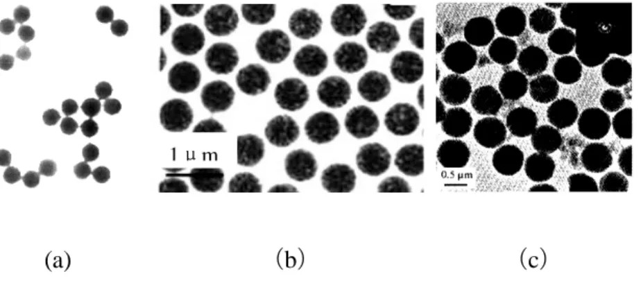
The polymer microsphere has a good dispersivity and an easily adjustable particle size. It is usually used to synthesize the spherical-shaped particles or near-spherical core-shell and the hollow structure after modifying the surface of the particles. Lin et al. [93] synthesized the compound of PSA / ZnS / CdS core-shell structure by using homemade polystyrene - acrylic microspheres (PSA) as a template using the dip method. Then, the template PSA was removed with toluene solution, finally obtaining ZnS / CdS composite hollow microspheres, whose microsphere size can be regulated by the amount of emulsifier. Figure 2.13 shows the particle morphology during various preparation stages.
(a) (b) (c)
Figure 2.13: TEM images of ZnS/CdS composite hollow microspheres prepared by PSA (a) PSA, (b) PSA/ZnS/CdS, (c) ZnS/CdS
Hard template is a commonly used method for the synthesis of nanostructured materials such as nanoparticles, nanorods, nanowire, nanotubes, nanobelts and so on in recent years. Since the method is capable of preparing templates with different nano-hole size and structure under various requirements, using physical or chemical growth or deposition of nanomaterials in nanopores for nanomaterials fabrication, the dimensions and specifications of target production can be precisely controlled.
Because of the stability of hard template structure, it is often used as the "micro reactor" in synthesis, during which a precursor is filled into the pores of the hard template or absorbed at its surface by impregnation or chemical vapor deposition method. The special structure of the hard template restricts the crystallization or aggregation of the precursors, and a mesoscopic phase having a structure opposite to that of the template can be obtained with the removal of template material by the appropriate method. Particles with different morphologies can be obtained by choosing hard templates with different structures.
2.3.2 Soft template
The soft template does not have a fixed rigid structure. In the synthesis of nanoparticles, an aggregate with some certain structural features is formed by means of the intermolecular or intramolecular interaction force (hydrogen bonding, chemical bonding and static electricity). Inorganic species are deposited on the surface or the interior of these templates by means of electrochemical method, precipitation and other synthetic methods, forming particles with certain shape and size. Common soft template can be a surfactant, polymer and bio-polymer, etc. The soft template has broad prospects for development in the synthesis of nanomaterials because of its advantages such as its good repeatability, simplicity of the process and no requirement for the removal of silicon [94-98].
a) Surfactants
Surfactants are amphiphilic molecules, including ammonium salts, heterocyclic, carboxylic acid salts, sulfonate salts and other ionic or non-ionic surfactants. It is easy for the amphiphilic molecule groups to form a variety of ordered polymers in a solution, such as liquid crystals, vesicles, micelles, microemulsion, self-assembled film, etc. [99, 100].
From the perspective of material chemistry, it is generally thought that the interaction between liquid crystal phase of surfactants and organic - inorganic interface play a decisive role in the morphology of mesoporous materials [101, 102]. In the strongly acidic environment, the interaction between the organic - inorganic interface is weak hydrogen bonds, while in a strong alkaline environment, it is strong electrostatic attraction. Liquid
crystalline phases formed by surfactants in the solution have various structures, such as lamellar phase, cubic phase, hexagonal phase, etc. It is also easy to construct and adjust [103]. Therefore, it is an ideal reactor for synthesizing mesoporous materials. The lamellar, cubic, hexagonal structures are shown in Figure 2.14.
Figure 2.14: Structure of liquid crystals
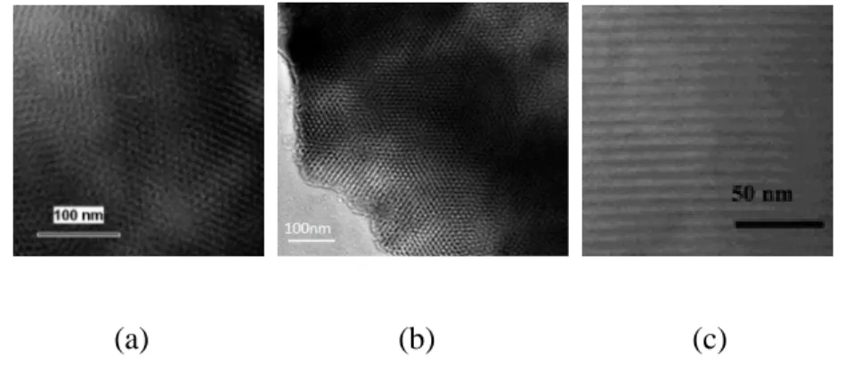
It is relatively easy to control the hydrolysis and polymerization of silicon species. Moreover, mesoporous silica with fibrous, thin film, tubular, spherical and other different morphologies can be obtained by combining the collective effect of surfactants and the reaction environment. Zhang et al. [104] synthesized worm-like monodisperse mesoporous silica microspheres in neutral alcohol - water system by using laurylamine as surfactant, tetraethyl orthosilicate as silicon source. The silica microsphere is shown in Figure 2.15 (a). The pore diameter can be regulated and controlled by adjusting the molar ratio and the concentration of the reactants and the ratio of alcohol/water. Wang et al. [105] synthesized mesoporous silica thin film in an acidic environment, which is shown in Figure 2.15 (b),
using tetraethyl orthosilicate as silicon source, cationic surfactant cetyltrimethylammonium bromide as template.
(a) (b)
Figure 2.15: TEM images of mesoporous silica (a) silica microsphere (b) mesoporous silica thin film [105]
b) High polymer
High polymer is often used as a template for the synthesis of mesoporous materials because of its large molecular weight, good stability and diversity of molecular structures. The pore structure and the morphology play a decisive role in the application of mesoporous materials. In recent years, researchers have emphasized the importance of controlling the morphology of mesoporous materials [106, 107], as different forms correspond to different application fields.
High polymer as a template and organic precursor form a certain liquid crystal structure by self-assembly method. In the fine crystal nucleation process, the selectivity of high polymers and certain crystal phase interact with each other, promoting or inhibiting the growth of crystal and thereby controlling and improving the morphology, size and distribution of particle. Li et al. [108] successfully synthesized cuprous oxide crystals, which is lamellar, urchin-like, one-dimensional line and acicular, in CuSO4 and Na2SO3
system by using polyacrylamide (PAM) as template and adjusting the concentration of Cu2+, PAM content and temperature. The lamellar, urchin-like and acicular cuprous oxides are shown in Figure 2.16.
(a) (b) (c)
Figure 2.16: TEM images of cuprous oxide crystals (a) lamellar cuprous oxide crystal, (b) urchin-like cuprous oxide crystal, (c) acicular cuprous oxide crystal [108]
Block copolymer is one of the most important high polymers, which is connected by polymer chains with two or more different properties. During the process of synthesis of mesoporous materials, hydrogen bonding occurs as the hydrophilic segments and precursors interact with each other which results in the formation of the ordered mesoscopic phase. The pore diameter of the mesoscopic phase is determined by the
hydrophobic chain of the block copolymer. Therefore, the larger the molecular weight of hydrophobic segment is, the stronger the hydrophobic property is, and the larger the synthesized pore diameter is[109].
c) Biopolymer
Since biopolymer has the advantage of availability in wide variety of sources, its complex structure, non-toxicity and easy removal, etc., it has great potential to be used as a template in synthesis of other materials. By means of inducing the biomineralization of inorganic nanoparticles, biopolymer synthesizes nanomaterials can have certain structures.
Common biopolymers are DNA, proteins and polysaccharides, etc. Wang et al. [110] using linear DNA molecules of the same length as a template and controlling the synthesis of DNA sequences, synthesized petaloid and spherical gold nanoparticles. Zhang et al. [111] successfully synthesized hierarchical porous SnO2 nanomaterials that have a structure of
cotton fibers by using cotton as a template and respectively adopting solvothermal method, ultrasonic method and impregnation method.
Li and Zhao [112] schematically summarized two synthetic strategies of soft template method as shown in Figure 2.17. There are two common mechanisms of the soft template: inorganic species and surfactants directly have supramolecular self-assembly, forming organic-inorganic phase. The organic and the inorganic species can combine by electrostatic bonding, hydrogen bonding or covalent bonding. The interaction between
inorganic species and surfactants is weak. Hence it is necessary to add an intermediate phase as a link to connect them, forming a stable organic-inorganic phase.
Figure 2.17: Mechanism of soft template method [112]
In the self-assembly process, inorganic species interact with surfactants driven by electrostatic force, covalent bond or hydrogen bond. The interaction of the organic (surfactants)/inorganic (inorganic species) interface is a weak hydrogen bond force in the strong acid environment while it is a strong electrostatic attraction force in the strong alkaline environment. Thus, inorganic species at the interface polymerize and crosslink, and assemble with surfactants [113, 114].
2.3.3 Comparison of hard and soft template
Hard template is mainly used for some previously prepared template material, such as AAO template, mesoporous carbon, polymer microsphere and so on. Hard template has
high reproducibility and stability, and it is mostly used for synthesis of arrays of nanomaterial. However, the separation of template and production may cause damage to the structure of nanotubes, nanowire or hollow balls.
On the other hand, soft template is mainly based on action of the micelle which form organic-inorganic phase between surfactant, high polymer and biopolymer, and target product. The aggregation by weak intermolecular or intramolecular interaction creates a certain structure of space. Such aggregates have significant structural interface. Soft template is formed during the reaction whereas hard template is prepared before the reaction. Hence, soft template is easier to build and remove than the hard template. It does not require complex equipment and strict production conditions and the reaction can easily be controlled. Soft template is mostly used to produce various size and sharp structure of nanomaterials.
2.4 The effect of calcination system on the morphology of alumina
The alumina calcination system is very important for obtaining nanoparticle powder with monodispersity and uniform morphology. Nano Al2O3 powder, which is composed of
widely used α-Al2O3, γ-Al2O3 and amorphous Al2O3, is generally obtained from alumina
precursor calcined at different temperatures. Therefore, the compaction among alumina particles of high activity is inevitable at high temperature. Thes results in severe particle agglomeration and resintering of individual particles with surrounding ones after melting with a formation of dendritic structure called "neck formation" of particle [115]. The result
have a significant effect on the morphology of alumina. While the temperature is less than 800ºC, alumina particles can continue to maintain their original morphology. If the temperature becomes higher than 800ºC, the activity of alumina particles is enhanced, and agglomeration begins to occur [116]. Ceresa et al. [117] first presented the relationship between temperature and phase transformation of alumina during the calcination process.
Figure 2.18: The relationship between temperature and phase transformation of alumina [118]
It can be seen from Figure 2.18 that the calcination temperature and time have a significant influence on the transformation of alumina (crystal type). When alumina particles calcined at the desired temperature in order to obtain certain crystal types, the calcination time depends on the size of the precursor. The smaller the particle size of precursor is, the shorter the time required for the calcination is and the higher the temperature of the heat treatment is, the shorter the time required for the calcination is. The
method of controlling the temperature and time during the calcination of Al2O3 is
well-known. This method ensures that while the Al2O3 particles go through a complete phase
change, their morphology remains unaffected and the dispersion of particles are reduced [118].
A significant amount of research is carried out in this area. Effective methods are proposed to control the morphology of alumina particles such as using DI water, alcohol and organic solvent mixtures to wash precursor before calcination in order to prevent agglomeration, enhance the dispersion, and increase the specific surface area of alumina [119]. In addition, the sintering properties of the powder can be improved with ultrasonic pretreatment, so that the neck formation created by agglomeration of the particles will not occur until 1400ºC [120]. The phase transformation temperature of γ-Al2O3to α-Al2O3 can
be decreased if sintering is carried out under the CO2 or ethanol atmosphere, consequently,
the well-crystalline spherical α-Al2O3 is eventually obtained [121].
Dispersants and surfactants also play an effective role in dispersion of particles and control of agglomeration. For example, using poly (methacrylic acid), organic acid, glucose, sucrose, inorganic salts, trimethylsilane and other additives [122], which results in a strong electrostatic repulsion among particles, eventually change the polarity of the particle surface from hydrophilic to hydrophobic (water-repellent). Polyacrylamide, silica gel and lignin and other polymer dispersants can form a protective layer with certain strength and thickness on the particle surface and prevent the agglomeration of the particles [123]. Surfactants can form a coating layer of several nanometers on the surface of the particles,
which can reduce the surface energy and effectively hinder the interactions among the particles [124].
Besides, by adding 5 wt% α-Al2O3 seed and 44% NH4NO3 during the calcination
process, the phase transition temperature can be decreased from 1200ºC to 900ºC [125].
The amorphous Al2O3 particles obtained at 600ºC is light yellow while the additive is
still present on the surface of the particles. This coating gradually disappears while 800ºC is reached. In addition, some additives can decrease the phase transition temperature of α-Al2O3 to 1000ºC. As the temperature increases, the grain size of Al2O3 will inevitably
increase, meanwhile the agglomeration will start to occur. This is due to the fact that when Al2O3 is completely transformed to α phase, the spatial arrangement of the O2 in α- Al2O3
occurs, which is the reconstruction of phase transition from face-centered cubic to hexagonal close packed lattice [126]. The effect of different parameters on the properties of alumina nanoparticles has been published and presented in Appendix I.
2.5 Summary
The production of Al2O3 can be influenced by various factors such as raw materials,
concentration, different synthesis methods, additives, heat treatment system, etc. During the preparation of Al2O3, the morphology of the precursors and the protection of the particles
during heat treatment play a decisive role in the final morphology of alumina. The morphology will not change during the low temperature heat treatment. However, when high temperature is reached, the diffusion of the powder particles accelerates. Thus, the
particles diffuse from the inside to the surface of the crystal lattice and spread to the surrounding resulting in the neck formation as well as the agglomeration of surrounded particles. The morphology of the particles changes accordingly. The use of various additives effectively reduces the calcination temperature; consequently, the problem of particle agglomeration can be solved. The utilization of template is a new research hotspot with the objective of improving the dispersibility of Al2O3 powder and controlling the
Chapter 3
Methodology
3.1 Experimental
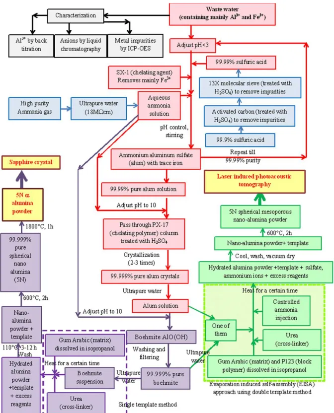
The schematic of the methodology is shown in Figure 3.1. It includes: 1. Characterization of the wastewater
2. Treatment of the reagents and improve the purity
3. Preparation of high purity alum solution from the wastewater
4. Production of 5N (99.999% pure) spherical alumina nanoparticles by single templating
5. Production of 5N (99.999% pure) spherical mesoporous alumina nanoparticles by double templating
6. Application of the 5N alumina nanoparticles in different fields: a. Preparation of sapphire crystal
b. Photoacoustic tomography

![Figure 2.7: SEM images of alumina particles with different molar ratio of [Bmim] PF 6 and aluminum isopropoxide (a) Al 2 O 3 -0, (b) Al 2 O 3 -0.03, (c) Al 2 O 3 -0.12, (d) Al 2 O 3 -0.18,](https://thumb-eu.123doks.com/thumbv2/123doknet/7595748.232668/35.918.254.753.152.509/figure-images-alumina-particles-different-molar-aluminum-isopropoxide.webp)
![Figure 2.10: Synthesis of gold nanowires using porous aluminum oxide membrane template [73]](https://thumb-eu.123doks.com/thumbv2/123doknet/7595748.232668/41.918.367.645.146.463/figure-synthesis-nanowires-using-porous-aluminum-membrane-template.webp)
![Figure 2.18: The relationship between temperature and phase transformation of alumina [118]](https://thumb-eu.123doks.com/thumbv2/123doknet/7595748.232668/53.918.238.771.389.710/figure-relationship-temperature-phase-transformation-alumina.webp)