ARTICLE BASED THESIS PRESENTED TO
ÉCOLE DE TECHNOLOGIE SUPÉRIEURE
IN PARTIAL FULFILLEMENT OF THE REQUIREMENTS FOR THE DEGREE OF DOCTOR OF PHILOSOPHY
Ph. D.
BY
Niloofar KAMKAR ZAHMATKESH
WATER DROPLET EROSION MECHANISMS OF TI-6AL-4V
MONTREAL, OCTOBER 28th, 2014
This Creative Commons license allows readers to download this work and share it with others as long as the author is credited. The content of this work can’t be modified in any way or used commercially.
BY THE FOLLOWING BOARD OF EXAMINERS
Mr. Philippe Bocher, Thesis Supervisor
Mechanical Engineering Department at École de Technologie supérieure
Mr. Florent Bridier, Thesis Co-supervisor Research Engineer at DCNS Research
Ms. Ruxandra Botez, President of the Board of Examiners
Automated Production Engineering Department at École de technologie supérieure
Mr. Mohammad Jahazi, Member of the jury
Mechanical Engineering Department at École de technologie supérieure
Mr. Pawel Jedrzejowski, External Evaluator Energy Sector, Rolls-Royce Canada, Ltd.
Mr. Swami Swaminathan, Independent Evaluator
President & Principal Metallurgical Consultant, TurboMet International
THIS THESIS WAS PRENSENTED AND DEFENDED
IN THE PRESENCE OF A BOARD OF EXAMINERS AND PUBLIC ON OCTOBER 16th, 2014
To my loving parents, Raz Amini and Ghasem Kamkar and my supportive brother, Bahram without whom I would have never finished this work.
ACKNOWLEDGMENT
This research effort would not have been possible without the guidance and support of my advisor, Professor Philippe Bocher and my co-advisor, Dr. Florent Bridier. Thank you, Philippe, for giving me the opportunity to work with you over the course of this Ph.D. Your continuous support, patience and immense knowledge helped me in all the time of this research and writing this thesis. Thank you, Florent, for all that you have taught me. You are a dedicated professional who have never denied me help when asked even though you were quite busy. I respect and admire you both, for being awesome mentors.
I would also like to thank Dr. Pawel Jedrzejowski for your help and insightful comments during this project. Professor Mohammad Jahazi Professor Ruxandra Botez, and Dr. Swami Swaminathan, thank you for serving on my committee and providing guidance toward the completion of this degree.
I would like to thank Professor Mamoun Medraj, for the experiments done at Concordia University. I would like to appreciate the help and support provided by Dr. Andreas Uihlein, Alstom, Switzerland for running the rig test at Alstom. I also thank Mr. Marin Lagace, Hydro-Quebec, for your help on doing the confocal microscopy at IREQ.
I would like to acknowledge the help of entire materials laboratory at ETS, particularly Radu Romanica, Jean-Guy Gagnon, and Olivier Bouthot. I am indebted to my colleagues helping me at materials lab, especially Dr. Majid Hosseini for helping me through the experiments at the beginning of my work, Dr. Vincent Savaria for helping me learn ANSYS and Polyworks software, Dr. Nicolas Vanderesse for doing the image processing job on my SEM images and EBSD maps, and Dr. Hossein Monajati for all the residual stress measurements and ANSYS works. I would also like to thank Mr. Mohammad Sadegh Mahdipoor, for all the great helps you provided me during the experiments at Concordia University. I wish you all success in your endeavors. My sincere thanks extend to all my colleagues at LOPFA. Thank you for
your discussions, supports, kind words, and well wishing. I would like to express my sincerest thanks to Dr. Jean-Charles Stinville. Thank you, Jean-Charles, for always being there for me, your discussions, and all the fundamentals you taught me.
This work was supported financially by Rolls-Royce Canada Ltd., the Consortium for Research and Innovation in Aerospace in Quebec (CRIAQ) under CRIAQ-MANU419 project and Natural Sciences and Engineering Research Council of Canada (NSERC). The financial support is gratefully acknowledged.
Finally, though no amount of “Thank yous” will suffice, I would like to wholeheartedly thank my parents and my only brother, the foundation of my life, for their support and encouragement throughout my entire life. Dad, thank you for your love of life. For allowing me paint on your canvas when I was a little girl. You are my first art teacher. Thank you for telling me what I am cable of and for never saying “no” when I asked for any helps. You will always be my hero. Mom, thank you for spending countless hours after you got home from work to patiently teach me math. Not that you only taught me math, I have learned what true compassion, unconditional love, and being a selfless person really mean. Bahram, you are the highlight of my childhood. You never wanted to see me get hurt and I felt all safe when you were around. Thank you for all the times you listened to me and gave me a shoulder to cry as if nothing else mattered. Without each of you, I would be nowhere near the person I am. I love you all.
Niloofar KAMKAR ZAHMATKESH
RESUMÉ
L’érosion par impact de gouttelettes est un phénomène pouvant mener à la ruine de matériaux métalliques dans de nombreux environnements. A titre d’exemple, l'érosion par gouttelette d’eau de pluie ou de vapeur sur les composants aéronautiques tels que les aubes de turbomachines et certaines parties du fuselage peut induire la détérioration progressive de ces dernières. Dans le cas spécifique des turbines à gaz couplées avec un système de brumisation (Inlet Fogging System), ce phénomène d’érosion est un point clé dans le dimensionnement de pièces.
Le système de refroidissement par brumisation est la méthode la plus couramment utilisée dans les turbines à gaz pour compenser les variations de température entre les saisons. Une augmentation trop importante de la température provoquant une chute des performances de la turbine à gaz. L’introduction de gouttes d’eau dans le flux d’air en entrée permet alors la régulation de la température des systèmes d’admission et du compresseur et ainsi une puissance de sortie optimale des turbines à gaz. Cependant, l’endommagement par érosion induit par l’introduction de ces gouttelettes d’eau sur les premiers étages du compresseur est problématique.
L'objectif principal de ce travail (projet CRIAQ MANU419) est de comprendre les phénomènes induits par érosion par impact de gouttelette sur un alliage de titane, afin d'optimiser la résistance à l'érosion des aubes de compresseur généralement produites à base de titane. La caractérisation des phénomènes d’endommagement par érosion par impact de gouttelettes sur un Ti-6Al-4V a été de première importance. Les effets de la microstructure du matériau ainsi que des paramètres d’impact des gouttelettes ont été mis en évidence. Ce travail sur la caractérisation de l’endommagement de l'érosion sur l'alliage Ti-6Al-4V s’articule en deux parties :
- L’endommagement par érosion par impacts de gouttelettes à travers une approche expérimentale originale. Les données collectées ont été traitées à la fois qualitativement et quantitativement pour effectuer une étude multi-échelle de l’endommagement.
Les effets de l’influence de la vitesse d'impact sur les phénomènes d’érosion afin de représenter les sollicitations induites en service.
Mots-clés : Impact de gouttelette d’eau, Érosion, Ti-6Al-4V, Turbine à gaz, Texture
ABSTRACT
Water impingement erosion of materials can be a life-limiting phenomenon for the components in many erosive environments. For example, aircraft body exposed to rain, steam turbine blade, and recently in gas turbine coupled with inlet fogging system. The last is the focus of this study.
Inlet fogging system is the most common method used to augment gas turbine output during hot days; high ambient temperature causes strong deterioration of the engine performance. Micro-scaled droplets introduced into the inlet airflow allow the cooling of entering air as well as intercooling the compressor (overspray) and thus optimizes the output power. However, erosion damage of the compressor blades in overspray stage is one of the major concerns associated with the inlet fogging system.
The main objective of this research work (CRIAQ MANU419 project) is to understand the erosion induced by water droplets on Titanium alloy to eventually optimize the erosion resistance of the Ti-based compressor blade. Therefore, characterization of the water droplet erosion damage on Ti-6Al-4V receives the major importance. The influence of base material microstructure and impact parameters were considered in erosion evaluation in present study. This work covers the characterization of the erosion damage on Ti-6Al-4V alloy in two parts:
- The water droplet erosion damage through a novel experimental approach. The collected data were processed both qualitatively and quantitatively for multi-aspects damage study. - The influence of impact velocity on erosion in an attempt to represent the in-service conditions.
Keywords: Water impingement, Erosion, Ti-6Al-4V, Gas turbine, Crystallographic texture,
TABLE OF CONTENTS
Pages
INTRODUCTION ...1
CHAPTER 1 LITERATURE REVIEW ...5
1.1 Erosion mechanisms ...5
1.2 Erosion behavior in Titanium alloys ...8
1.3 Water impingement parameters and their influence on the erosion kinetic ...12
1.3.1 Impact velocity... 12
1.3.2 Impact angle ... 13
1.3.3 Droplet size ... 14
1.4 Conclusions of literature review and refining the problematic ...15
1.5 Materials and the experimental plans accordingly ...17
1.5.1 Base materials under investigation ... 17
1.5.2 Coupons and erosion rig set up ... 19
1.5.3 Erosion curves ... 21
1.5.4 Erosion characterization ... 22
1.5.5 Summary of the experimental plans ... 22
CHAPTER 2 ARTICLE 1: WATER DROPLET EROSION MECHANISMS IN ROLLED TI-6AL-4V ...25
2.1 Introduction ...26
2.2 Materials and methods ...28
2.2.1 Materials ... 28
2.2.2 Hardness of investigated alloy relative to measurement direction ... 30
2.2.3 Water erosion testing ... 31
2.2.4 Methodology for erosion craters characterization ... 32
2.3 Results ...33
2.3.1 Cumulative mass loss during erosion testing ... 33
2.3.2 Macroscopic characterization of erosion craters ... 34
2.3.3 Microscopic analyses of eroded sample ... 35
2.4 Discussion ...38
2.5 Conclusions ...42
CHAPTER 3 ARTICLE 2: WATER DROPLET IMPACT EROSION DAMAGE INITIATION IN FORGED TI-6AL-4V ...45
3.1 Introduction ...46
3.2 Materials and methods ...48
3.2.1 Experimental set up and water erosion test ... 48
3.2.2 Materials and sample preparation ... 50
3.2.3 Characterization procedure and methodology ... 53
3.3.1 Cumulative XIVmass loss curve ... 54
3.3.2 Macroscopic observation of the damage ... 55
3.3.3 Microscopic observation of the damage ... 57
3.3.4 Local microplasticity ... 64
3.4 Discussion ...66
3.5 Conclusions ...68
CHAPTER 4 ARTICLE 3: INFLUENCE OF WATER DROPLET IMPACT VELOCITY ON EROSION OF TI-6AL-4V ...73
4.1 Introduction ...73
4.2 Materials and methodologies ...75
4.2.1 Materials and sample preparation ... 75
4.2.2 Hardness of investigated alloy relative to measurement direction ... 77
4.2.3 Experimental set up and water erosion test ... 78
4.2.4 Characterization procedure and methodology ... 79
4.3 Results ...80
4.3.1 Cumulative mass loss during erosion testing ... 80
4.3.2 Macroscopic observation of the damage ... 81
4.3.3 Microscopic analyses of eroded samples ... 84
4.3.4 Cracks behavior quantification ... 85
4.4 Discussion ...88
4.4.1 Incubation period and erosion rate ... 88
4.4.2 Width and depth of damage ... 90
4.4.3 Erosion mechanisms ... 93
4.5 Conclusions ...95
CHAPTER 5 DISCUSSION ...99
5.1 Erosion mechanisms ...99
5.2 Influence of microstructural characteristics ...102
5.3 Representativeness of the in-service conditions ...105
5.4 Erosion resistance and application of surface treatment ...106
CONCLUSIONS ...109
RECOMMENDATIONS ...113
ANNEX I Influence of droplet size on water droplet erosion mechanisms of Ti-6Al-4V ...117
ANNEX II Surface treatment influence on water droplet erosion resistance on Ti-6Al-4V ...121
APPENDIX I Erosion mechanisms of rolled and forged Ti-6Al-4V presented at EPRI/RSE erosion conference, June 2012 ...127
LIST OF TABLES
Page
LIST OF FIGURES
Page
Figure 1-1 The schematic of liquid-solid impact stress and shock wave formation and possible microcrack caused by the impact (taken from Zhou et al. 2009) ...6 Figure 1-2 Correlation of σ΄f n΄ and mean depth of penetration
(taken from Richman and McNaughton 1990) ...8 Figure 1-3 Correlation of σ΄f n΄ and incubation time (taken from Richman and
McNaughton 1990) ...8 Figure 1-4 Angular variation of E in uniaxial loading
(taken from Bridier et al. 2008) ...9 Figure 1-5 Inverse pole figure projection of elastic anisotropy (E)
(taken from Bridier et al. 2008) ...10 Figure 1-6 Basal : ‹a›, prismatic ‹a›, pyramidal ‹a› slip systems, and first and
second-order pyramidal ‹c+a› slip systems in hcp materials (taken from Balasubramanian and Anand 2002) ...10 Figure 1-7 Average erosion rate vs. impact velocity (taken from Lee et al. 2003) ...13 Figure 1-8 Typical solid particle erosion behavior of ductile and brittle
materials as a function of impact angle (Taken from Haungen et al. 1995) ...14 Figure 1-9 SEM micrograph showing the grain morphology: a) forged and
b) rolled base materials ...17 Figure 1-10 Pole figures showing the crystallographic texture of the grains:
a) forged and b) rolled base material ...18 Figure 1-11 SEM micrograph showing the microstructure of cold-rolled plate:
a) low and b) high magnification ...19 Figure 1-12 Pole figures of the cold-rolled plate ...19 Figure 1-13 Coupons extracted from a) forged and b) rolled base materials. The
Figure 1-14 Schematic drawing of the water droplet erosion test bench of a) Alstom (taken from www.materials-laboratory.power.alstom.com)
and b) Concordia ...21
Figure 1-15 Materials and experimental plans ...23
Figure 2-1 SEM micrograph of rolled microstructure a) lower and b) higher magnification ...29
Figure 2-2 Large EBSD map of rolled microstructure ...29
Figure 2-3 Pole figures of rolled microstructure ...29
Figure 2-4 Microhardness values for rolled Ti-6Al-4V on different surface ...31
Figure 2-5 Schematic of the eroded sample with three lines of water droplet impingement on top surface ...32
Figure 2-6 Cumulative mass loss vs. number of water droplet impingements ...34
Figure 2-7 Localized damage craters induced by water droplets ...35
Figure 2-8 Cross-sectional view illustrating craters depth and lateral sub-tunnel formation (white arrows) ...35
Figure 2-9 Surface (white arrows) and sub-surface (black arrows) cracks ...37
Figure 2-10 Crack propagation cases ...38
Figure 2-11 Example of rough and smooth surface along erosion crater’s edge ...38
Figure 2-12 Schematic of the water polishing mechanism ...39
Figure 2-13 Distribution in size of the cracks measured along the craters edges ...41
Figure 2-14 Distribution of cracks inclination relative to water droplets impact direction ...41
Figure 3-1 Schematic of the eroded sample with three lines of water droplet impingement on top surface ...49
Figure 3-2 Back-scattered electron micrograph of forged microstructure: a) lower and b) higher magnification ...51
Figure 3-3 Large EBSD map of the typical forged microstructure used for water impingement test (Y is the impingement direction). Zone A and B are macrozones found in the forged microstructure ...51
Figure 3-4 a) pole figure of overall forged microstructure shown in Fig. 3-2 and, b) local macrozone A, (Y is impingement direction) ...52 Figure 3-5 Secondary electron micrograph revealing electro-polished surface prior to erosion tests ...53 Figure 3-6 Normalized cumulative mass loss vs. number of water droplet
impingements ...55 Figure 3-7 SEM micrograph of erosion features typical of the incubation period
(1000 impingements) showing: a) large scale and, b) high magnification ...56 Figure 3-8 SEM micrograph of erosion features at onset of material removal
(20000 impingements): a) traces of erosion line and b) high magnification of the erosion line (zone A to D present the erosion progression) ...56 Figure 3-9 SEM surface protrusion at initial stage of erosion from Fig. 3-7 (1000
impingements): a) zone A and b) zone B ...57 Figure 3-10 AFM topography of a) original surface, and b,c) surface protrusions at
(1000 impingements) ...58 Figure 3-11 Section analyses of the protrusions heights, (1000 impingements) ...59 Figure 3-12 Grain tilting observed around zone A after water droplet impacts
(20000 impingements): a) large scale b) high magnification ...60 Figure 3-13 AFM height profiles of a) original surface and b)early damage
induced by few droplets (20000 impingement stage) ...61 Figure 3-14 Section height profile across the tilted grains (20000 impingement):
a) AFM height image showing the extracted profiles, b) extracted height profile of line a, and c) extracted height profile of line b...62 Figure 3-15 Intergranular damage observed at zone B (20000 impingements):
a) large scale, b) high magnification ...63 Figure 3-16 SEM micrograph of features observed at zone C
(20000 impingements): a) triple junction and material tear off, b) material chip off and micro-voids formation ...64 Figure 3-17 SEM micrograph of features at zone D (20000 impingements):
a) Crater formation and striation marks, b) deepening the craters and slip lines around the craters ...64
Figure 3-18 Slip bands a) incubation period (1000 impingements) and b) onset of material removal (20000 impingements) ...65 Figure 3-19 Sample cross section revealing underneath of the protrusions,
(20000 impingements) ...66 Figure 3-20 Protrusions without cracks underneath (20000 impingements): a) large
scale and b) higher magnification ...66 Figure 4-1 a) pole figure of the blade material, b) pole figure of
rolled microstructure ...77 Figure 4-2 SEM micrograph of rolled microstructure: a) lower and b) higher
magnification ...77 Figure 4-3 Schematic of the sample with an erosion line due to water droplet
impingements on top surface and the reference directions of the cold rolled plate ...79 Figure 4-4 Cumulative mass loss vs. impingements number and time of exposure ....81 Figure 4-5 Localized damage lines induced by water droplets with varied impact
velocity; a, b, and c) same amount of material loss (0.005g) and d, e, and f) same impingements number (100000) ...82 Figure 4-6 Initial damage induced with few impingements; a) 350 m/s, b) 300 m/s, and c) 250 m/s ...83 Figure 4-7 Cross-sectional view illustrating craters depths, and lateral sub-tunnel
formation (white arrows): a, b, and c) same amount of material loss (0.005g) and d, e, and f) same impingements number (100000) ...84 Figure 4-8 Cross sectional view of cracks behavior ...85 Figure 4-9 Distribution in size of the cracks measured along the craters edges: a)
same amount of material loss (0.005g) and b) same impingements number (100000) ...86 Figure 4-10 Distribution of cracks inclination relative to water droplets impact
direction: a) same amount of material loss (0.005g) and b) same
impingements number (100000) ...87 Figure 4-11 a) 350 m/s impacted coupon showing larger cracks with preferential
orientation, b) 300 m/s impacted coupon showing smaller cracks which are not yet oriented in a preferential direction (RD), and c) Sub-tunnels formation in preferential orientation (RD) ...88
Figure 4-12 Relation between impingement number showing the incubation time and impact velocity ...89 Figure 4-13 Erosion rate (Cumulative mass loss/cumulative time) vs. (cumulative
mass loss per impingement number) after the incubation period ...90 Figure 4-14 Erosion rate vs. impact velocity (after incubation period) ...90 Figure 4-15 Relation between impact velocity and MDE ...92 Figure 4-16 Influence of the impact velocity on erosion damage depth rate ...93 Figure 4-17 Amount of material loss at acceleration stage vs. V2 ...94 Figure 5-1 Water droplet erosion curves for forged and rolled Ti-6Al-4V ...103 Figure 5-2 a) pole figure presenting the typical texture of cold rolled
Ti-6Al-4V, and b) sample extraction and impingement directions relative to the texture ...114
LIST OF ABREVIATIONS
AFM Atomic Force Microscopy
ASTM American Society for Testing and Materials EBSD Electron Back-Scattered Diffraction
HLP High Load Parameters
ID Impingement Direction
LCF Low Cycle Fatigue
LD Longitude Direction
LLP Low Load Parameters LPB Low Plasticity Burnishing LSP Laser Shock Peening MDE Mean Depth of Erosion
MUD Multiple of Uniform Distribution
ND Normal Direction
PDA Phase Doppler Anemometry PMMA PolyMethyl-MethAcrylate
RD Rolling Direction
RPM Revolution Per Minute
SEM Scanning Electron Microscopy
SiC Silicon Carbide
TD Transverse Direction
LIST OF SYMBOLS C Speed of the sound in a liquid
E Young’s modulus
Ed Erosion damage depth
Ek Impact energy
ER Erosion rate
hcp Hexagonal closed pack Ip Incubation period
L Crack size
n Erosion velocity exponent n΄ Cyclic strain hardening
P Induced pressure by a single droplet on a surface Rd Erosion damage depth rate
t Testing time
V Impact velocity
ɛ̇ Erosion rate
Ɵ Angle/inclination ρ Density of liquid droplet
INTRODUCTION
Liquid impingement erosion is the result of high speed liquid droplets impacting a solid surface. It has become a significant issue in several conditions such as rain erosion in aircrafts, missiles, and helicopter rotors (Heymann 1992) or more recently, in gas turbine engine applications where inlet fogging and overspray are used to increase the performance and power efficiency during hot days (Khan 2008, Bhargava et al. 2007). Inlet fogging is the most common method used to increase power during hot days due to its low cost. Water droplets are sprayed into the gas turbine inlet to cool the entering air to the engine and increase the air density. Remaining water droplets will enter the compressor, resulting in inter-cooling and increasing the output power (Giampaolo 2006). However, the most challengeable concern is the potential erosion of compressor blades resulted from entering the remaining water droplets to the compressor (over spray stage) which will reduce engine efficiency on a long run.
This research project is part of the CRIAQ MANU 419 project in collaboration with Rolls-Royce Canada. It pursues the main objective of improving the compressor components with a higher water erosion resistance. There are three research groups working on this project: Concordia University group who is working on developing the coatings and modeling of the water erosion phenomenon as well as manufacturing the water erosion rig, École Polytechnique de Montréal group who is also developing hard and super hard coatings, and École de Technologie Supérieure (ÉTS) whose objective is to understand the erosion mechanisms of Ti-6Al-4V alloy used for the in-service compressor blade. As a consequence, the present work mainly focuses on investigating the erosion mechanisms on initial as well as advanced stages of erosion. The influence of impact velocity is investigated regarding to the in-service conditions of the compressor blades.
Over the past decades solid particle erosion has been mostly studied rather than liquid impact erosion. A large number of investigators worked on material removal behavior and especially the influence of impact parameters on erosion damage induced by solid particle on the solid
surface. Fewer studies recently investigated liquid impingement erosion. The concept of erosion rate dependence on mechanical properties or impact parameters received the major dedication through the previous works on liquid impact erosion. Erosion was investigated on various materials with great attempts on correlating the erosion phenomenon with material or mechanical properties like hardness, modulus of elasticity, ultimate tensile strength, etc. (Mann and Arya 2002, Heymann 1969). There are, however, only few studies focused on erosion mechanisms and in particular on the characterization of the damage through the different stages of erosion. In addition, there is little complete experimental data in the literature explaining the erosion mechanisms relative to other impact properties such as velocity. Understanding the influence of all impact parameters is beyond the scope of this work.
Following the water erosion resistance improvement of compressor components, the main objective of the present study is the characterization of water droplet erosion mechanisms on Ti-6Al-4V alloy and the influence of base-material and impact properties relative to the in-service conditions. To reach the main objective, the sub-objectives are defined as follow;
- To understand the erosion mechanisms of Ti-6Al-4V alloy during the material removal process
o To analyze the erosion behavior during the incubation stage o To analyze the advanced stages of material removal
- To describe the influence of microstructural properties of base-material o To investigate both rolled and forged microstructure of Ti-6Al-4V
- To understand the influence of water droplets impact velocity on erosion kinetic of Ti-6Al-4V
To tackle these objectives, the document begins with a comprehensive overview of the erosion mechanisms and material removal behavior under water droplet impacts given in Chapter 1. The different viewpoints of previous investigators are discussed. Their attempts to obtain some correlations between the erosion mechanisms and mechanical or material properties are presented. This chapter also includes the review of the important parameters
which influence the erosion resistance and behavior of the materials; typically, impact velocity and droplet size.
The first scientific article published from this work is presented in Chapter 2. It discusses the mechanisms of erosion at the advanced/steady state stages for a rolled Ti-6Al-4V. An original methodology is introduced to investigate different aspects of the erosion behavior. In particular, the crack propagation modes are quantified for the first time in impact erosion phenomenon. The relation of the crack propagation including nucleation is discussed relative to the rolled microstructural properties. A new mechanism for material removal is proposed for the erosion due to water droplet impingements. This chapter responds to the second part of the first objective which is to better understand and discuss the water droplet erosion mechanisms of Ti-6Al-4V alloy concentrating on crack nucleation and material removal.
The initial stages of erosion damage on forged Ti-6Al-4V have been addressed in a second article which is presented in Chapter 3. The mechanisms involved at the earlier stages of material removal are investigated through different techniques such as Scanning Electron Microscopy (SEM) and Atomic Force Microscopy (AFM). The evidence of micro-plasticity, grain tilting and intergranular damage due to droplet impacts is discussed and a novel mechanism of damage initiation is proposed. Transgranular sub-surface cracks formation and surface protrusions were observed as the first indication of damage initiation. This chapter responds to the first part of the first objective, meaning understanding the nucleation of cracks at early stages of erosion. Chapter 2 and 3 together discuss the influence of microstructure on erosion mechanism and respond to the second objective of the work.
The third article of this work investigates the influence of water droplet impact velocity on erosion behavior of Ti-6Al-4V in Chapter 4. Impact velocity is the parameter which influences the most the kinetics of erosion phenomenon (Hattori 2010). The influence of the impact velocity is investigated both qualitatively and quantitatively. The base material and velocities range are selected based on the in-service conditions of gas turbines to simulate various regions of compressor blades. This work responds to the third objective of the
project, which is to understand the influence of representative impact velocities on erosion behavior. Other parameters should be investigated in future works for fully representation of the in-service conditions.
Finally a substantial summary and discussion of the research work presented in Chapters 2 to 4, is given in Chapter 5. It allows the outcomes of this work to be linked to obtain the objective of the work and discusses the understanding of the erosion phenomenon in certain aspects. Conclusions of the work are presented afterwards in this chapter following by general remarks and recommendations.
CHAPTER 1 LITERATURE REVIEW
The progressive material loss induced by repeated solid or liquid impacts is called impact erosion. There are many kinds of erosion such as solid particle erosion, slurry erosion and abrasion, cavitation erosion, and liquid impingement erosion. Comparing with other kinds of erosion such as solid particle erosion, the liquid impingement erosion has been less studied. Especially there is a relatively limited experimental work on high velocity liquid impact erosion (Zhou et al. 2008) which is the main concern of gas turbines using inlet fogging systems. Understanding the erosion problem may be divided into two major parts. The first part of the problem is relevant to erosion resistance and material removal mechanisms and the second part is the particular influence of the water impingement conditions, such as angle, velocity, size, and etc. The first part of the problem which is understanding the mechanisms of the erosion has generally received less attention than the second part for which more studies may be found in the literature and are discussed afterward in Chapter 4. Erosion can be generally divided in two main stages, i.e., the initial stages of erosion damage and the advanced material removal. The later received the major attention among previous studies while there is limited work on initial stages of erosion. For the purpose of this thesis, the review of the literature is limited here to two sections: discussing the previous work on erosion mechanisms and reviewing the influence of main water impingement parameters on erosion behavior.
1.1 Erosion mechanisms
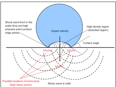
The simplest mechanism of water impact erosion is referred to as the “water hammer”, and ‘‘water hammer pressure’’ known as the pressure induced by the droplet impact on the surface which is confirmed by Heymann (1969). At a certain moment during the impingement, shock waves develop in the droplet and breaks away. The lateral out flow forms after and the energy transforms to kinetic energy and impact pressure is released into the base material. Shock wave formation is well known in a droplet impacting a solid. The
shock wave characteristics and stress field generation are presented in Fig. 1-1 (Zhou et al. 2009).
Figure 1-1 The schematic of liquid-solid impact stress and shock wave formation and possible microcrack caused by the impact (taken from Zhou et al. 2009)
Various explanations are reported for material removal mode and great attempts were made in the past also on correlating the erosion with static mechanical properties such as energy absorption, hardness, elastic modulus, or ultimate tensile strength and some correlations have found so far (Garcia and Hammitt 1967, Rao et al. 1970, Frees et al. 1983, Feller and Kharrazi 1984). The common outcome for liquid impact erosion was that, in most cases, improving base material strength properties such as hardness and yield strength increases the erosion resistance.
Another explanation for erosion resistance is its correlation with fatigue resistance of materials (Schmitt 1979). Indeed, due to the repetitive nature of water droplet impingement at high frequency, the erosion process may be associated with cyclic loading and fatigue-like mechanism. Fatigue-like mechanisms were reported for liquid impingement erosion by Hancox and Brunton in 1966; however, fatigue-based theory was initially developed by Richman and McNaughton in 1990 for cavitation erosion damage. They collected data on
various metals and alloys to correlate the cavitation erosion resistance with the introduced fatigue strength coefficient, σ΄f which is a measure of cyclic stress resistance and n΄ which is the cyclic strain hardening coefficient. The coefficients, σ΄f and n΄, are firstly introduced by Manson and Hirschberg in 1963, through an equation to obtain the relation between total strain and number of cycles. The values can be obtained from cyclic strain-stress curve, strain-life curve, and in some cases from stress based tests reported in the literature (see Manson and Hirschberg 1963). Richman and McNaughton (1990), showed that product of σ΄f and n΄ (σ΄f n΄) presents a strong correlation between the erosion damage and cyclic deformation properties as is presented in Figs. 1-2 and 1-3. In the same way, features such as striations which accompanying fatigue, were previously reported by Marriott and Rowden (1966) investigating the cobalt-chromium alloy. Afterwards, Beckwith and Marriott (1967) investigated the rain erosion damage on chromium steel and their attempt to correlate the incubation time to the number of cycles for crack nucleation in bending fatigue showed good agreement. Similarly, Thomas and Brunton (1970) observed striation marks investigating the liquid impingement erosion of 50/50 brass. They suggested that fatigue is one probable mechanism of failure in erosion because the liquid impact erosion may be similar to the fatigue phenomenon as the loading is repetitive. A fatigue-based mechanism for water droplet erosion has been however recently questioned by Mann and Arya (2002) since they did not detect any fatigue features neither for cavitation, nor for water jet impingement of Ti-6Al-4V.
Figure 1-2 Correlation of σ΄f n΄ and mean depth of penetration (taken from Richman and McNaughton 1990)
Figure 1-3 Correlation of σ΄f n΄ and incubation time (taken from Richman and McNaughton 1990)
1.2 Erosion behavior in Titanium alloys
Among the influencing parameters on erosion behavior, material properties such as microstructure should not be neglected. The impact of local microstructure on solid and liquid particle erosion was shown by some researchers (Yerramareddy and Bahadur 1991,
Huang et al. 2012). Schmitt (1979) reported that, erosion mechanisms even in a certain material can be varied relative to its microstructure.
Microstructural effect might have a considerable influence on erosion behavior of Titanium alloy due to its anisotropic behavior. The material under investigation in this study is a duplex Ti-6Al-4V, i.e. composed of globular primary hcp grains and secondary hcp α-plates, embedded in a bcc β matrix. Duplex Titanium alloys with mainly hcp α-phase and some area of α secondary embedded in bcc β-matrix are known to display elastic/plastic anisotropy. Anisotropy exists in this alloy mainly due to the strong crystallographic texture induced due to the processes like rolling and texture effects play a significant role in the technological characteristics of Titanium alloys.
To explain the elastic anisotropy of duplex Titanium alloys, the angular variation of the Young’s Modulus (E) is presented graphically in Fig. 1-4 where Ѳ is the angle between the c-axis and the loading direction. As is shown when Ѳ=0˚ meaning when the loading direction is parallel to c-axis, the maximum Young modulus (≈145 GPa) is achieved, while when Ѳ=90˚ and the loading direction is perpendicular to the c-axis the minimum Young modulus (≈100 GPa) is reported. The inverse pole figure projection of elastic anisotropy is presented in Fig. 1-5.
Figure 1-4 Angular variation of E in uniaxial loading (taken from Bridier et al. 2008)
Figure 1-5 Inverse pole figure projection of elastic anisotropy (E) (taken from Bridier et al. 2008)
Plastic anisotropic is also reported for Titanium alloys and is generally related to the different slip systems activated within a particular crystallographic texture. The plastic slip systems for duplex Titanium alloy are presented in Fig. 1-6.
Figure 1-6 Basal : ‹a›, prismatic ‹a›, pyramidal ‹a› slip systems, and first and second-order pyramidal ‹c+a› slip systems in hcp materials (taken from Balasubramanian and
Anand 2002)
For instance, Bache and Evans (2001) illustrated the significant differences in monotonic and cyclic loading properties of a rolled Ti-6Al-4V relative to the loading axis; rolling and transverse directions. They showed that loading in transverse direction promotes the yield stress and ultimate tensile strength. For the cyclic loading, loading along the rolling direction offers the optimum cyclic response as well as the increase in stress relation. Therefore, due to
the pronounced elasto/plastic anisotropic behavior of Ti-6Al-4V, an influence of the microstructural conditions on water impact erosion mechanisms may be expected.
Few studies tackled the influence of microstructural features on water erosion resistance. The major contribution on initial damage investigation for a range of materials under water droplet impacts suggest that surface plastic deformation followed by pit formation and surface cracks formation as the damage initiation mechanisms (Thomas and Brunton 1970, Futakawa et al. 2003, Date and Futakawa 2005, Kong et al. 2010). Water droplet erosion mechanisms were investigated by some researchers on pure Titanium and a range of Titanium alloys and their erosion resistance was correlated to their hardness level (Yasugahira et al. 1990). A recent work reported sub-surface plasticity through hardness variations for Ti-6Al-4V submitted to plain water jet impingements without giving clear evidence (Chillman et al. 2007). Intergranular damage is also stated as the dominating mechanism for damage initiation in Ti-6Al-4V alloy under similar test (Huang et al. 2012) however there is no work stating transgranular damage at the initiation stages. The initial damage induced by water droplet is not comprehensively documented and there is still a need of initial local erosion damage investigation. Adler et al. (1974, 1976) reported also crack observations in Ti-6Al-4V subjected to supersonic rain erosion and reported the similarities between fatigue and erosion mechanisms. Similar observations were also stated by Robinson et al. (1995) for untreated and laser treated Ti-6Al-4V under water droplet erosion tests. However, they did not provide distinct evidence of fatigue features and, therefore, the cyclic nature of material removal is still indeterminate.
The detailed review of the literature on the advanced and initial erosion mechanisms is presented in chapter 2 and 3 followed by discussing the work to fully characterize the erosion damage induced by water droplet impacts on Ti-6Al-4V alloy. Damage initiation and advanced material removal behavior are discussed on two separate articles with regards to the microstructural aspects.
1.3 Water impingement parameters and their influence on the erosion kinetic
A good contribution of previous studies is on understanding the influence of operational parameters on erosion behavior of materials. The main influencing factors in impact erosion are reported to be impact velocity, impact angle, and drop shape and size.
1.3.1 Impact velocity
The impact velocity plays the most important role in distinction of erosion and corrosion phenomena as well as influencing the erosion behavior (Adler et al. 1972). Coulon (1985) defined the range of velocities for turbines in PWR power station where the corrosion and erosion phenomena can be formed. The velocity ranges achieved by him are presented in Table 1.1.
Table 1.1 Phenomenon defined in velocity range (taken from Coulon 1985) Phenomenon Velocity m/s Corrosion 0-10 Corrosion-erosion 10-50 Erosion-corrosion 50-200 Erosion 200+
Significant amount of work was carried out on the influence of impact velocity on erosion rate. It is reported that the relation between erosion rate (ɛ̇), usually defined as the cumulative volume or weight loss per erosion time, and impact velocity (V) is in the form of:
ɛ̇ α Vn (1.1)
where n values varies for different materials (Yerramareddy and Bahadur 1991, Ahmad et al. 2009). Lee et al. (2003), in their investigation on steam turbine blade erosion tested different
alloys for the calibration of erosion parameters. They have converged for a common n value about 5 for all the investigated alloys. Fig. 1-7 shows the influence of increasing the impact velocity on erosion rate for some alloys including Ti-6Al-4V. Therefore, increasing the impact velocity is logarithmically proportional to increasing the erosion rate, though it is desired for gaining the required efficiency (Schmitt 1979). Moreover, the variation of the speed along the leading edge for the compressor blades makes it interesting to investigate in the present study how erosion features changes with the variation of speed. This point will be specifically addressed in Chapter 4.
Figure 1-7 Average erosion rate vs. impact velocity (taken from Lee et al. 2003)
1.3.2 Impact angle
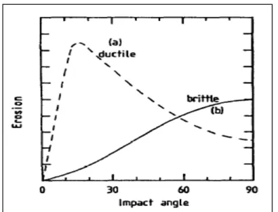
The effect of impact angle is mainly discussed in solid particle erosion. Generally in solid impact erosion, maximum material removal occurs at 90˚ for brittle materials such as TiN and Titanium whereas the corresponding angle for ductile materials such as Copper, Aluminum, etc. is 22.5˚. Fig. 1-8 shows the influence of impact angle on erosion behavior of ductile and brittle material in solid impact erosion (Haugen et al. 1995).
Figure 1-8 Typical solid particle erosion behavior of ductile and brittle materials as a function of impact
angle (Taken from Haungen et al. 1995)
In case of liquid droplet erosion, since the roughness of the surface changes continuously during the process, the impact angle is not stable. Therefore due to this complexity there is no certain conclusion on the angle of maximum erosion rate (Heymann 1992, Stanisa and Ivusic 1995). This gets more complex for the in-service conditions as the droplets impact the leading edge of compressor blades with the varied angles that induce different types of material removal modes and damage extents.
1.3.3 Droplet size
Adler (1995) found that the damage induced by water droplet erosion is strongly influenced by the droplet radius at the point of impact and not the droplet mass. Indeed shapes of droplets are not perfectly spherical due to different condition of injection force, gravity, etc. In this matter, the equivalent diameter which is the diameter of the flattened droplet that causes more damages is considered as the influencing diameter (Field 1999).
Increasing the droplet size, results in increasing the material removal if the number of impingements is constant (Lee et al. 2003). In water droplet erosion of the blade since there is wide range of droplet sizes, the mean diameter is used in the investigation of erosion (Lee et al. 2003).
On the subject of droplet size, it is noteworthy that one of the issues concerning the use of inlet fogging system in gas turbine engine is the droplet sizing. This is mainly important because of the wide range of statistically distributed droplet size created by the fog nozzles, droplet coalescence, etc. (Chaker et al. 2004).
The influence of droplet size has been studied in the present work and is presented in Appendix I.
1.4 Conclusions of literature review and refining the problematic
The review of the previous work was made in this chapter on general erosion mechanisms and the influencing parameters.
The considerable amount of works on advanced stages of erosion with attempts to correlate the erosion resistance with the mechanical properties did not introduce a clear pattern, even if the general outcome shows that erosion resistance increases with increasing the strength properties. A number of mechanisms were indicated in the literature for material removal phenomenon including fatigue-like mechanism for a range of materials, though the erosion behavior of Titanium alloys, specifically Ti-6Al-4V, has not been well-defined. Also the previous studies concentrated mainly on the mechanical nature of water droplet erosion for advanced stages of erosion, while the number of research on material properties such as microstructural influence is very limited typically on water droplet impingement of Titanium alloys. Thus it is worth to fully characterize both initial and advanced damage induced by water droplet impact erosion considering the local microstructure. The mechanisms of
erosion are comprehensively described and discussed in Chapter 2 and 3 presenting the erosion behavior at advanced and initial stages of erosion, respectively.
Among the influencing parameters, impact velocity is deemed to have the major influence on the erosion behavior. Increasing the velocity increases the initial kinetic energy resulting in more material loss. Experiments were conducted on the influence of the particle velocity on material loss rate and the relation is given by a power law. The power exponent for Titanium alloy was found to be 5.1 under a certain conditions (Lee et al. 2003). Specifically, the influence of impact velocity on erosion rate of Ti-6Al-4V alloy for the in-service speeds has not been studied as for the knowledge of the author, neither the mechanism of material removal is discussed for this alloy. Chapter 4 discusses the previous works in detail and presents the erosion behavior examination of the representative impact velocities to the in-service conditions.
Certain coupons were already available at the beginning of this PhD project, provided by Rolls-Royce. Several batches of tests were performed on different materials with specific test equipment due to sample and equipment availabilities. In particular some coupons were already tested at Alstom whose raw materials were hardly available. Thus, complementary tests were performed to build a scientific approach to the problem, but all possible combination could be studied. Moreover, the type of microstructure or texture of the coupons under investigation was not necessarily the one that would represent the industrial conditions. Some of the complementary tests were then run on new microstructure and using a new rig available at Concordia University to obtain the most possible coherent results. Therefore in light of the experimental procedures and materials under investigation in this work a summary of the test methods used to obtain the erosion mechanism and meet the objectives are presented hereafter. Following is the chart briefly explains the materials and tests in order to make it clearer for the reader.
1.5 Materials and the experimental plans accordingly 1.5.1 Base materials under investigation
Characterization of the base material is conducted at macro and micro scales as well as texture analyses using SEM and Electron Backscattered Diffraction (EBSD) maps at ETS using Schottky-SEM Hitachi SU70. EBSD is a quantitative method of microstructure characterization for the crystalline materials. Material characteristic such as grain size, grain boundary character, grain orientation, texture, and phase identification as well as meso/macro crystallographic texture of the material can be obtained through EBSD analyses.
The erosion mechanism is studied for two base materials divided into two parts: initial and advanced stages of erosion. Characterizations of the two base materials are made at macro- and micro-scales. The brief presentation of the base materials’ microstructure and texture is presented in Figs. 1-9 and 1-10. The microstructures are very different both morphologically and crystallographically. The erosion evaluation is done relative to the two presented microstructure and the comparison is made in terms of the damage features and kinetic of the process.
Figure 1-9 SEM micrograph showing the grain morphology: a) forged and b) rolled base materials
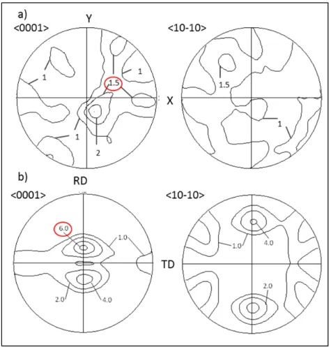
Figure 1-10 Pole figures showing the crystallographic texture of the grains: a) forged and b) rolled base material
On the other hand there is another rolled material used for the analyses of the impact velocity effect (Chapter 4). This cold-rolled plate is selected based on the in-service blade microstructure and texture so that it represents the similar characteristics to the blade material. The microstructure and texture of the material is presented in Figs. 1-11 and 1-12.
Figure 1-11 SEM micrograph showing the microstructure of cold-rolled plate: a) low and b) high magnification
Figure 1-12 Pole figures of the cold-rolled plate
1.5.2 Coupons and erosion rig set up
Coupons are extracted from the presented base materials and the erosion tests are performed on different basis explained later in following chapters to reach a specific objective. The coupons from the forged base material are in a bolt shape and from the two rolled base materials are flat (Fig. 1-13).
Figure 1-13 Coupons extracted from a) forged and b) rolled base materials. The impingement surface is showed with the arrows
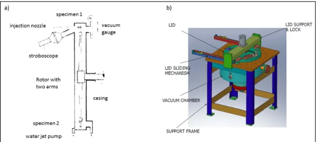
Water erosion test are performed on the coupons either at Alstom, Switzerland (for the first two objectives: understanding the erosion mechanism as well as influence of the microstructure), or at Concordia university, Canada (for the study of impact velocity influence). While there are some differences between the two water erosion rigs, the principals are the same. It means a static rig in which droplet streams are fixed and the coupons rotate. Through each revolution coupons hit the droplet stream. Therefore the impact velocity in the present study refers to the coupons rotational or linear speed. In the same regard, the number of impingements denotes the number of times the coupon intersects the droplet stream (once per revolution). The differences between the two rigs are mostly related to the number of nozzles (three vs. one for Alstom and Concordia rigs respectively), vertical (Alstom) and horizontal (Concordia) rotations, type of nozzles, speed limits (higher speed limits for rig at Concordia compare to Alstom) and accuracy. The schematic of the water droplet erosion rig is illustrated in Fig. 1-14.
Figure 1-14 Schematic drawing of the water droplet erosion test bench of a) Alstom (taken from www.materials-laboratory.power.alstom.com) and b) Concordia
The eroded coupons then present three lines of erosion if eroded at Alstom (Chapter 2 and 3) and one erosion line if at Concordia (Chapter 4) as presented in the following chapters.
1.5.3 Erosion curves
To obtain the erosion curves for all the investigated conditions, the interrupted tests were run until the coupons reach to the advanced stages of erosion. At each interruption based on the number of impingements or exposure time, the coupons are weighed and in the end, erosion curves are obtained through measurements of cumulative mass loss versus impingement numbers. Obtaining an erosion curve is a time consuming process as it requires a good time around 5-10 minutes between the each interval weighing the sample, turning off and on the machine, waiting for vacuum chamber to reach a certain value, etc. This time plus the run time of the machine is the required time to get one erosion curve. For the investigation of the coupons at different stages of erosion, once the erosion curves are obtained, the erosion stages can be identified. Then, other bare coupons were tested until the exact desired point on the curve (erosion stage). These points were obtained either based on the number of impingements or the exposure time of erosion. Certain set ups and conditions used for each test are discussed through the following chapters.
1.5.4 Erosion characterization
Erosion characterizations are done on the coupons at different erosion stages using SEM at macro and microscopic scales as well as quantitative measurements. This provides the information on the erosion behavior at different scales and reveals the macro and micro-scopic aspects of the erosion i.e. the features which are only visible through e.g. macro or microscopic observations. Quantitative measurements are performed in order to quantify the observations for example the sizes of cracks, inclination, etc.
Macroscopic analyses of the erosion are carried out through width and depth of the erosion lines as a parameter to identify the erosion mechanism. These analyses are made observing the erosion damage from above the coupons or through cross sectional polishing and measurement of the damage depth.
On the other hand, microscopic evaluation mainly addresses the crack studies in terms of nucleation and propagation modes. Observations are done on both eroded surfaces and cross sections which lead to obtain information about the possible sub-surface damages.
Quantitative evaluation is mainly important to give a quantified insight on the dependence of the damage generated by water droplet erosion relative to base material microstructure. It is done through measurement of hundreds of cracks’ size and inclination. Crack inclination is referred to the angle of crack propagation relative to the erosion plane. The rules used in the measurement of size and inclination are presented in Appendix II.
1.5.5 Summary of the experimental plans
The following chart (Fig. 1-15) describes all the materials under investigation and corresponded tests as whole.
CHAPTER 2
ARTICLE 1: WATER DROPLET EROSION MECHANISMS IN ROLLED TI-6AL-4V
N. Kamkar 1, F. Bridier1, P. Bocher1, P. Jedrzejowski2
1Mechanical Engineering Department, École de Technologie Supérieure (ÉTS), 1100 Notre-Dame Ouest, Montreal, QC, Canada H3C 1K3
2Rolls-Royce Canada Ltd-Energy, 9545 Cote-de-Liesse, QC, Canada H9P 1A5 This article has been published in Wear, vol. 301 issue 1-2 (2013), pp. 442-448. DOI:
10.1016/j.wear.2013.01.005
Abstract
Water impingement erosion of Ti-based parts is an issue encountered in many situations: aircraft body exposed to rain during flight, steam turbine blade, and inlet fogging used in gas turbines. The present work focuses on identifying the mechanisms of water droplet erosion of Ti-6Al-4V. Coupons of rolled Ti-6Al-4V have been exposed to high-speed water impingement erosion tests up to the advanced stage. Progressive cross-sectional polishing revealed both surface and sub-surface damage features at different scales. Qualitative observations and quantitative measurements were done on the eroded surface craters. Many micro-cracks along the erosion craters have been observed. The damage appeared to be dependent on the local microstructure morphology and the crystallographic texture of base material. A progressive mechanism for water droplet erosion during maximum erosion rate stage is proposed. It involves the nucleation of crack networks under the droplets impingements, cracks’ propagation and/or merging, tunneling or removal of large fragments of material due to linkage of cracks, water smoothing and, cyclically, nucleation of new sets of cracks.
2.1 Introduction
Liquid impingement erosion is the result of high-speed liquid droplets impacting a solid surface. It has become a significant issue in several applications such as low-pressure steam turbine blade as well as rain erosion in aircraft, missile and helicopter rotors [1]. Water droplet erosion could also be a challenge in gas turbines equipped with inlet fogging [2, 3]. Water droplets are sprayed into the gas turbine inlet and cool the air entering to the engine. Remaining water droplets enter the compressor (over spray), resulting in the inter-cooling of the compressor and increasing of the output power [4].
Erosion under impingement of water has been studied by several authors over the years. The mechanical nature of erosion under water droplets or jet impingement is recognized by most of the researchers. Obara et al. [5] highlighted the strong influence of tensile stress waves on the occurrence of cracks during the impact of a liquid jet on polymethyl-methacrylate (PMMA). The resistance of base-materials to water impingement erosion is then generally linked to various mechanical properties of the investigated alloy: absorption energy, hardness, toughness, elastic modulus, or ultimate tensile strength. Regarding Titanium alloys, Yasugahira et al. [6] correlated the water droplet erosion resistance of pure Titanium and a range of Titanium alloys with their respective Vickers hardness. Adler et al. [7, 8] also reported in the 1970s the observation of cracking within a Ti-6Al-4V alloy submitted to supersonic rain erosion and underlined the similarities between fatigue and erosion mechanisms. Particularly, localized cracks and lateral sub-tunneling phenomena were reported at that time for the investigated Titanium alloy. Similar observations were made twenty years later by Robinson and Reed [9] who studied the water droplet erosion of untreated and laser surface treated Ti-6Al-4V. They revealed micro-cracking and suggested a link between erosion resistance and fatigue resistance, without however giving clear evidence of fatigue-related damage along the analyzed erosion craters. For cavitation erosion, Richman and McNaughton [10, 11] compiled a lot of data obtained on various metallic materials and also suspected the cyclic nature of erosion under repeated loading. They qualified the cavitation erosion process as a cyclic deformation mechanism and introduced
the fatigue strength coefficient as a driving parameter for cavitation resistance. Mann and Arya [12], however, questioned in 2002 the theory of Richman and McNaughton as they did not observed fatigue cracks neither for cavitation nor for water jet impingement of Ti-6Al-4V and other alloys. The cyclic nature of erosion damage and the intrinsic mechanism of material removal are nowadays still unclear. Moreover, the particular influence of the microstructure has not been specifically investigated, particularly in the case of water impingement at advanced stages of erosion of Titanium alloys which present very fine-grained and complex microstructures. The impact of local microstructure was shown for sand-blast erosion as Yerramareddy and Bahadur [13] related solid particle erosion with microstructural precipitation due to thermal ageing of Ti-6Al-4V. The microstructural dependence of material removal at earlier stages of erosion under plain water jet impingement for Ti-6Al-4V were studied by Huang et al. [14], reporting the grain boundary damage as the most dominant mechanisms during the initial stages of erosion. If water impingement erosion induces high compressive and tensile stress/strain fields, localized plasticity is assumed to occur under the repetitive loading of water droplet impacts. It appears then very interesting to fully characterize the local erosion damage, particularly relative to surrounding microstructure.
The present work focuses specifically on liquid droplet erosion of Ti-6Al-4V, an alloy which is frequently used in low-pressure blades of steam turbines and compressor blades in gas-turbines, as well as many critical parts of aircrafts [1]. The advanced stages of water droplet erosion were investigated on rolled Ti-6Al-4V, with the objective of obtaining the erosion mechanism as well as influence of microstructure. A rolled microstructure was chosen for this study because it is characterized by a high anisotropy appropriate to investigate the effects of the microstructure on erosion mechanism.
2.2 Materials and methods 2.2.1 Materials
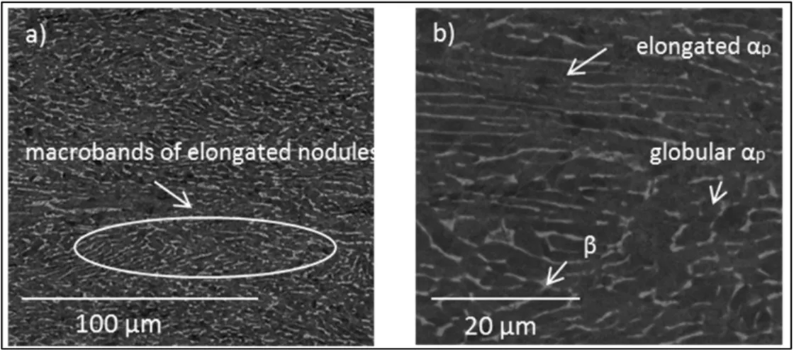
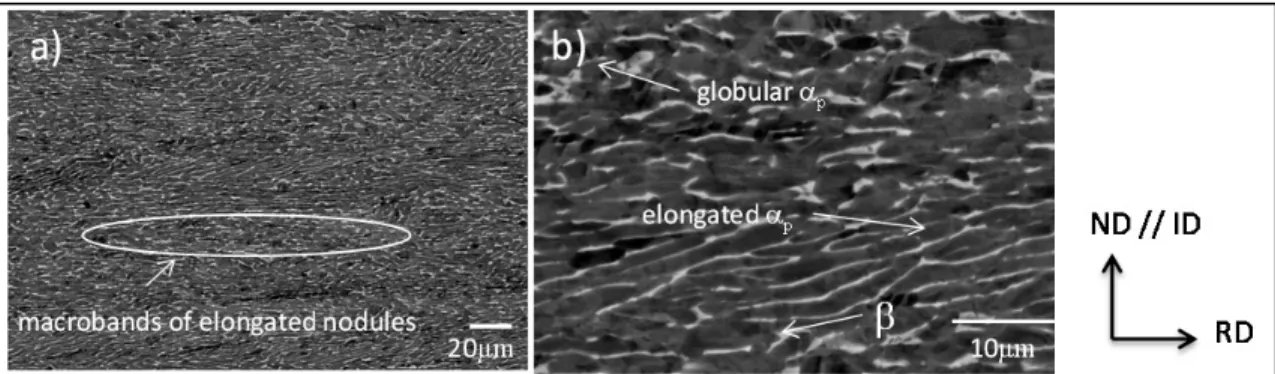
The base-material used for the study is a rolled Ti-6Al-4V. Analyses were conducted in terms of morphology and crystallographic texture of the microstructure using a scanning electron microscope (SEM) Schottky Hitachi SU70. The rolled Ti-6Al-4V microstructure is composed of elongated primary α-grains with locally some area of equiaxial α-grains (Fig. 2-1(a)). At a macroscopic scale, the elongated primary α-grains are organized into macro-bands of a few hundreds of micrometers. The presence of very fine secondary α-phase platelets embedded in a β-phase matrix can also be found as depicted in Fig. 2-1(b).
The crystallographic texture measurements were obtained by electron back-scattered diffraction (EBSD) with an Oxford- Channel 5 system. Large EBSD maps of 4.5x1.5 mm2 with a 2 mm step size were realized and are depicted in Fig. 2-2. The local crystalline orientation is given in the EBSD map relative to the droplets impingement direction (ID//ND). The corresponding pole figures for both (0001) and {10–10} planes were calculated from the EBSD data and are shown in Fig. 2-3. It can be noted that the present material presents a strong crystallographic texture. The maximal multiple of uniform distribution (MUD) factor is 6.38 for the {0001} pole figure. The preferential orientation indicates that most α phase presents a <0001> direction inclined by 15 degrees with the normal direction (ND) of the rolled plate. Due to the elasto-plastic anisotropy of the hcp α-phase in Titanium alloys, such a strong crystallographic texture is known to primarily influence the mechanical resistance of the alloy relative to the loading direction. As an example, Bache and Evans [15] showed an increase of yield strength from 970 MPa up to 1100 MPa between longitudinal and transverse direction of a highly textured rolled plate of Ti-6Al-4V. Similar anisotropy in fatigue resistance was observed and such differences in mechanical behavior were related to the ability to induce slip in the various plate orientations [16]. Therefore, the present rolled Ti-6Al-4V alloy is of particular interest in investigating the influence of the microstructure on the erosion resistance.
Figure 2-1 SEM micrograph of rolled microstructure a) lower and b) higher magnification
Figure 2-2 Large EBSD map of rolled microstructure
Figure 2-3 Pole figures of rolled microstructure
{0001} RD TD {11-20} 1.0 6.0 4.0 2.0 1.0 2.0 4.0
2.2.2 Hardness of investigated alloy relative to measurement direction
According to the literature, the hardness of the substrate is one of the important mechanical properties controlling the erosion resistance of a material [17, 18]. Even though they are results indicating the importance of other properties, it is generally accepted that increasing the hardness of the material results in increasing the erosion resistance. Hardness measurements of the investigated rolled microstructure were conducted on both the eroded surface, i.e., with a loading direction along ND//ID, and on the perpendicular plane ID-RD, i.e., with a loading direction along TD. The hardness measurements were realized using a Clemex CMT microhardness indenter with two loads (100g and 500g). Each hardness value is the average of minimum five indentations accurately measured under SEM. The hardness values are given in Fig. 2-4 for both directions ID and TD. The scatter of each measurement is given as an error bar reflecting maximal and minimal values. Note that the scatter of the results is reduced with 500g load relative to 100g since larger indents cover more grains and give more representative estimation of the hardness value in a single direction. Hardness values in the ID direction are much higher than in the perpendicular direction TD, i.e., 350 HV vs. 300 HV, approximately. It is interesting to note that this variation of hardness is in the same order of magnitude as the increase of hardness reported for some surface treatment of similar Titanium alloys. As an example, Kim et al. [19] reported an increase from 300 for base metal to 360 HV within the hardened layer of a Ti-6Al-4V submitted to various levels of Laser Shock Peening. As no residual stresses are present in the investigated material (in an annealed state), the increase of hardness for the rolled plate relative to indent direction can be directly linked to the strong crystallographic texture and the associated elasto-plastic anisotropy of the material.
Figure 2-4 Microhardness values for rolled Ti-6Al-4V on different surface
2.2.3 Water erosion testing
A flat sample of 25 mm length, 8 mm width and 3 mm thickness was used for the water droplet erosion tests. Fig. 2-5 shows a schematic of the sample with ID direction being the water droplet impingement direction. This direction is parallel to the normal direction (ND) of the rolled plate. The water droplet erosion tests were performed according to the ASTM international G73 standard [20] with three parallel nozzles leading to three lines of erosion craters depicted in Fig. 2-5. Rotational speed of the disk was 5500RPM with the arm length around 60cm which gives the linear impact speed of 350m/s. The linear speed was controlled by controlling the rotational speed of the rotor and the droplet speed was neglected with respect to linear speed which is set to 350m/s. The samples were subjected to repetitive impact under three parallel jets. The samples were impacted once per revolution. The term ‘‘number of impingement’’ will refer to the number of times the sample intersects the droplet stream.
This impact velocity is well within the regime where erosion is the main driving mechanism for wear of impacted surface [21]. An average droplet size of 0.6 mm was used. Droplet size was controlled by calibrated nozzles. Nozzle diameter was 0.3mm. Droplet size
ND // ID 100g ND // ID 500g TD 100g TD 500g 260 270 280 290 300 310 320 330 340 350 360 Microhardne ss (HV)
measurements were done according to Phase Doppler Anemometry (PDA) and it is validated for the 0.3mm diameter nozzle the mean droplet diameter is 0.6mm.
The impact angle was 90 degrees relative to impacted surface and tests were done at ambient temperature and the vacuum pressure was 25 mbar. After a certain number of impingements, the weight of the sample was precisely measured. The total number of impingements was estimated to 300,000 for the investigated sample.
Figure 2-5 Schematic of the eroded sample with three lines of water droplet impingement on top
surface
2.2.4 Methodology for erosion craters characterization
The characterization of the erosion damage was performed at advanced stages of erosion. Characterization methods were conducted through qualitative observation and quantitative measurements using SEM. The systematic investigation of the three erosion lines provided sufficient repeatability of the results. The erosion craters were characterized through observations of the eroded surface as well as by progressive cross sectional polishing of the ID-RD plane; i.e. to increase the statistics samples were polished and observed at different cross sections. In order to observe the cross sections, samples were finely cut with diamond blade, grinded and then polished using Buehler vibratory polisher on the cross surfaces. In order not to alter the erosion features, backscattered electron microscopy was used to reveal
the local microstructure along the erosion craters and no chemical etching was used. The damage caused by water erosion was imaged at various magnifications; typically at x50 for larger scale evaluation of craters and tunnels geometry, as well as at x2500 for cracks observations and measurements.
2.3 Results
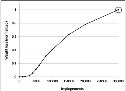
2.3.1 Cumulative mass loss during erosion testing
Fig. 2-6 gives the cumulative mass loss of the sample as a function of number of water droplet impingements. An initial incubation time may be observed up to 30,000 impingements, followed by an acceleration stage between 30,000 and 150,000 impingements and following by deceleration and steady state stage which are the advanced stages of erosion. This erosion kinetic under water droplet impingement has been largely described by Heymann [1], who for most materials identifies 5 successive stages: the incubation stage, the acceleration stage, the maximum rate stage, deceleration stage, and the final steady-state stage. Robinson et al. [9] reported the lack of any incubation time for a non-treated Ti-6Al-4V when exposed to droplets with an impact speed of 500 m s-1. Although the incubation period is not the focus of the present work, it is interesting to note that the cumulative mass loss versus impingement numbers did present an incubation time for the investigated rolled Ti-6Al-4V. As the impact velocity in the present study is 350 m s-1, i.e., lower than the velocity used by Robinson et al., it is possible that the initial mechanisms behind early stages of erosion might change for different microstructures and future work should concentrate on this issue. In the present work, the erosion features were only characterized on the very last interruption of the test, i.e., after 300,000 impingements. This stage is circled in Fig. 2-6 and is considered as advanced stages of erosion. As at this stage, the erosion craters are relatively deep, the erosion features at both macroscopic and microscopic scales were analyzed all along the craters edges. The mechanisms which will be identified from these observations are then valid to describe only the advanced stages erosion mechanisms. Future work are planned to consider the early stages of erosion by running water impingement erosion tests on a