HAL Id: hal-00597924
https://hal.archives-ouvertes.fr/hal-00597924
Submitted on 2 Jun 2011
HAL is a multi-disciplinary open access
archive for the deposit and dissemination of
sci-entific research documents, whether they are
pub-lished or not. The documents may come from
teaching and research institutions in France or
abroad, or from public or private research centers.
L’archive ouverte pluridisciplinaire HAL, est
destinée au dépôt et à la diffusion de documents
scientifiques de niveau recherche, publiés ou non,
émanant des établissements d’enseignement et de
recherche français ou étrangers, des laboratoires
publics ou privés.
A comparative study of 4-cable planar manipulators
based on cylindrical algebraic decomposition
Damien Chablat, Erika Ottaviano, Guillaume Moroz
To cite this version:
Damien Chablat, Erika Ottaviano, Guillaume Moroz. A comparative study of 4-cable planar
manip-ulators based on cylindrical algebraic decomposition. Proceedings of the ASME 2011 International
Design Engineering Technical Conferences & Computers and Information in Engineering Conference,
Aug 2011, Washington, United States. pp.1-10. �hal-00597924�
1 Copyright © 2011 by ASME Proceedings of the ASME 2011 International Design Engineering Technical Conferences & Computers and Information in Engineering Conference IDETC/CIE 2011 August 28-31, 2011, Washington, DC, USA
DETC2011/MECH-47726
A COMPARATIVE STUDY OF 4-CABLE PLANAR MANIPULATORS BASED ON
CYLINDRICAL ALGEBRAIC DECOMPOSITION
Damien Chablat
Institut de Recherche en Communications et Cybernétique de Nantes, UMR CNRS 6597, 44321 Nantes, France
Erika Ottaviano DiMSAT, University of Cassino G. Di Biasio 43, 03043 Cassino (Fr), Italy Guillaume Moroz
INRIA Nancy, LORIA - Campus Scientifique, 54506 Vandoeuvre-lès-Nancy, France
Associate Professor and corresponding author, +33240376948; fax: +33240376930; E-mail: Damien.Chablat @irccyn.ec-nantes.fr
ABSTRACT
The aim of this paper is to present a systematic method for verifying the force-closure condition for general 3-DOF fully-constrained cable manipulators with four cables as based on
the CAD (Cylindrical Algebraic Decomposition). A
fundamental requirement for a cable manipulator to be fully controllable is that all its cables must be in tension at any working configurations. In other words, all the cable forces must be positive (assuming a positive cable force representing a tension and a negative cable force being a compression). Such a force feasibility problem is indeed referred to a force-closure problem (also called vector-closure problem assuming that the vectors of interest are the row vectors of the Jacobian matrix of the manipulator). The boundaries of the workspace can be obtained by the study of the Jacobian matrix of the manipulator. Therefore, this is equivalent to study the singularity conditions of four 3-RPR parallel robots. By using algebraic tools, it is possible to determine the singularity surfaces and their intersections yielding the workspace. Thus, it will be shown that the use of the CAD allows to get an implicit representation of the workspace as a set of cells. A comparative workspace analysis of three designs of mobile platforms, a line, a square and a triangle will be presented and discussed in this paper for a planar 4-cable fully-constrained robot.
INTRODUCTION
Cable-based parallel robots, in which legs are replaced by cables, are structurally similar to the classical parallel ones, and they consist of a fixed base (or frame) and mobile platform, which are connected by several cables [1]. Unlike rigid links, the unilateral characteristic of the cables (can pull but cannot push moving platforms), and therefore the formulations and results obtained for the kinematics, workspace, trajectory planning, and dynamics of the rigid-link mechanisms cannot be directly applied. Hence, the main issue can be recognized in determining the poses whereby the moving platform can be fully constrained by the cables.
Due to the nature of cables, this type of parallel robots have in general good characteristics such as: good inertial properties, they can be modular, relatively low-cost, and easy to reconfigure. Moreover, their actuator-transmission systems can be fixed on the frame and cables are lighter and thus, they can have higher payload-to-weight ratio, which makes them attractive for a number of applications. According to their design, dynamics can be easily derived when the inertias of the cables can be neglected [2], and this holds for many practical applications if the cable mass is negligible if compared to the combined mass of the end-effector and payload.
types, the fully-constrained type and under-constrained type, based on the extent to which the end-effector is constrained by cables only or they rely on gravity [3], [5].
The necessary but not sufficient condition for a mobile platform with n degrees-of-freedom to have a fully-controlled motion is considering at least m = n + 1 cables, since many cable robots can be over-determined with respect to Forward Kinematics but under-determined with respect to cable forces distribution [5]. Therefore, a critical issue for their use is the evaluation of the cable force distributions. For cable-based parallel robots it is known that maintaining positive cable tension is critical in constraining the moving platform. Hence, the force-closure workspace is defined as the set of poses whereby resultant cable tensions can sustain an arbitrary external wrench acting on the moving platform.
A better control of the mobile platform can be obtained by increasing the number of actuated cables, which will also reduce the tension in each cable for a given payload, but the workspace will be limited by possible interferences among cables and cables with mobile platform [6].
Several workspace classifications have been proposed for fully constrained cable robots, namely the controllable [7], wrench feasible [8], dynamic [9] and force-closure [10], [11] workspaces. They are defined as the set of poses at which the mobile platform (or end-effector) can physically reach while all the cables have positive tension, and additional constraints are fulfilled. It is worth to note that in constraining positive cable tensions, main proposed analyses deal with the null space approach through pseudo-inverse matrices, graphical approaches, or condition expressed in terms of the convex hull which encloses the origin. Those approached have been applied to either planar and spatial cable-based parallel robots.
Many fully-constrained manipulators have been proposed for a number of possible applications, but feasible tasks are limited due to the increasing number of cables, [12], [13].
In this paper a systematic method of verifying the force-closure condition for general 3-DOF fully-constrained cable manipulators with four cables is proposed as based on CAD (Cylindrical Algebraic Decomposition).
A comparison of the workspace of different designs is presented and discussed. The CAD algebraic tool has been successfully used for the workspace analysis and singularity determination of classical parallel manipulators as reported in [14], [15].
ALGEBRAIC TOOLS
To analyze the workspace of a robot, we have to determine the equations that describe the Kinematics. These equations use trigonometric functions and we have to transform them to an algebraic system to make the CAD (Cylindrical Algebraic Decomposition).
Algebraic formulation of robotics problem
There are two methods to obtain algebraic equations starting from trigonometric equations:
Change an angle by 2 variables x, y and a constraint
equation 2 2 1 0
x y
where x cos
and
sin
y
. This change of variables allows us to avoid the sine and cosine functions and keep the system algebraic. Moreover, this change of variables does not introduce any spurious solutions since the function
,
(cos( ), sin( )) C (1)is bijective on the unit circle C .
Use the Weierstrass substitution. If we set
2
2 2
2 1
tan then sin( ) and cos( )
2 1 1 t t t t t (2)
The first transformation is used for all our computation except for the rendering. In this case, we introduce a singularity representation for .
Discussing the number of solutions of the parametric system
The workspace analysis requires the discussion of the number of solutions of the parametric system associated with the Inverse Kinematics. More precisely, we want to decompose the workspace in cells C1,...,Ck, such that:
Ci is an open connected subset of the workspace;
for all pose values in Ci, the Inverse Kinematics problem
has a constant number of solutions;
Ci is maximal in the sense that if Ci is contained in a set
E, then E does not satisfy the first or the second condition.
This analysis is done in 3 steps:
Computation of a subset of the joint space (resp. workspace) where the number of solutions changes: the
Discriminant Variety.
Description of the complementary of the discriminant variety in connected cells: the Generic Cylindrical
Algebraic Decomposition.
Connecting the cells belonging to the same connected component of the complementary of the discriminant variety: interval comparisons.
3 From a general point of view, the discriminant variety can
be defined for any system of polynomial equations and inequalities.
Let p1, ... pm, q1, ..., ql be polynomials with rational
coefficients depending on the unknowns X1, ..., Xn and on the
parameters U1, ..., Ud. Let us consider the constructible set:
n+ d
1 1
= v ,p ( )v 0,..., pm( )v 0,q ( )v 0, ...,ql( )v 0
C C (3)
If we assume that C is a finite number of points for almost all the parameter values, a discriminant variety VD of C is a variety in the parameter space d
C such that, over each connected open set U satisfying U VD , C defines an
analytic covering. In particular, the number of points of C over any point of U is constant.
Let us now consider the following semi-algebraic set:
n+ d
1 1
,p ( ) 0,..., pm( ) 0,q ( ) 0, ...,ql( ) 0
v v v v v
S C (4)
If we assume that S has a finite number of solutions over at least one real point that does not belong to VD, then
d D
V R can be viewed as a real discriminant variety of S, with the same property: over each connected open set d
U R such that
D
V
U , C defines an analytic covering. In particular, the number of points of R over any point of U is constant.
Discriminant varieties can be computed using basic and well known tools from computer algebra such as Groebner bases (see [16], Chapter 3) and a full package computing such objects in a general framework is available in Maple software through the RootFinding[Parametric] package.
Kinematics tool for the workspace analysis
The vector of input variables q and the vector of output variables X for a n-DOF parallel manipulator are linked by a system of non linear algebraic equations as
,
F q X 0 (5)
where 0 is the n-dimensional zero vector. Differentiating Eq. (5) with respect to time leads to the velocity model
0
A X B q (6)
where A and B are n n Jacobian matrices. These matrices
are functions of q and X
F F A B X q (7)
These matrices are useful for the determination of the singular configurations [17].
PLANAR 4-CABLE ROBOTS AND THEIR SUB-ASSEMBLY
Kinetostatics equations for 4-cable robots
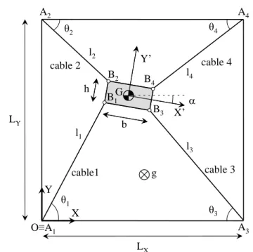
Let us consider a planar 4-cable robot shown in Fig. 1, it is composed by a fixed frame whose dimensions are LX and LY
and end-effector, whose dimensions are referred as b and h. The manipulator has four cables to constrain the end-effector 3-DOFs in the plane of motion XY. Let us consider the attachment points at the base named as Ai and those in the end-effector
named as Bi. The cables’ lengths li and i angles can be
evaluated as (for i = 1…4)
0,
A 0R
B i i i l P P (8)
sin co s tan co s sin iy ix iy i ix ix iy A y B B A x B B (9) in which P = 0 [ ] Tx y and represent the end-effector pose in the fixed frame and R is the rotation matrix, which relates the moving and fixed frames denoted as GX’Y’ and OXY.
A fundamental requirement for a cable manipulator to be fully controllable is that all its cables must be in tension at any working configurations. In other words, all the cable forces must be positive (assuming a positive cable force representing a tension and a negative cable force being a compression).
b h θ2 θ4 A2 A4 O≡A1 Y X X’ Y’ l2 l4 cable 2 cable 4 cable 3 cable1 θ3 θ1 g A3 l3 l1 B2 B 4 B1 B3 LY LX G
Such a force feasibility problem is indeed a force-closure problem (also called vector-closure problem in the mathematics literature where the vectors of interest are the row vectors of the Jacobian matrix of the manipulator).
Let us consider the wrench applied at G, which is the origin of the moving frame by the i-th cable in the form
T T i i ni
w f (10)
in which fi and ni are the force and moment about G
produced by the i-th cable. Since the abovementioned force is parallel to its corresponding cable and its related moment is perpendicular to the plane, they can be expressed as
i ti i
f u and
i d et i,i i
n R B tu (11)
In which ui is the unit vector along li and ti is the tension in
the i-th cable. If we arrange the wrench and tension in matrix form the static equilibrium equation for the end-effector can be expressed as
G
W t w (12)
in which wG is the wrench applied to the end-effector by
external forces and moments and can include gravity force, without loss of generality, and W represents the wrench matrix also called structure matrix [5], being J the transpose of W.
A cable-based parallel manipulator is said to have a force-closure in a particular pose if and only if any arbitrary external wrench applied at the moving platform can be sustained through appropriate tension forces in the cables [10].
In order to solve the force-closure problem, the linear system of equations given by Eq. (12) has to be solved.
From linear algebra, it is known that the vector sum of any solution of Eq. (12) with a vector in the null space of W is again a solution to Eq. (12) [1]. Therefore, if *
t is a solution of Eq. (12) and t being a vector in the null space of W, then the sum
,
t tt (13) is again a solution of Eq.(12).
Therefore, for a vector t whose components are all strictly positive, a sufficiently large scalar multiple of this vector can be added to any particular solution t of Eq. (12) to obtain a cable-tension vector t with positive components.
Several researchers pointed out that the force-closure problem of cable manipulators is similar to that of multiple fingers grasping a frictionless rigid-body [18]. In the former, all the cables must be in tension while in the latter all the fingers
must be in compression. Hence, the equilibrium equations with inequalities on cable tensions are similar to the equations of equilibrium for the grasped object with constraints on finger forces. Handling the force-closure problem of cable manipulators based on the similarity between cable manipulators and multi-finger hands can be found in [19] in which the antipodal method is used for the workspace analysis of planar cable robots.
A graphical method was proposed in [20] to determine the types of conic sections forming the boundary of the constant orientation wrench-closure workspace of a planar cable-robot, which were firstly determined in [21], and then obtained for the spatial case in [20], when a constant orientation of the moving platform is considered. In particular, it is shown in [23] that the boundaries of the constant orientation workspace of a cable robot consists of parts of cubic surfaces.
By reviewing the literature, it is worth to note that the determination of the boundaries of the wrench-closure workspace for any given planar cable-robot is still a challenging problem that has not been completely solved yet and it is worthy of investigation.
Singularity of 3-RPR parallel robot
Less work is done in developing systematic methods of judging whether the force-closure condition is satisfied for a given configuration of a cable manipulator. The proposed algorithm to determine the workspace of cable manipulator can be summarized in three steps:
1. Determine one pose where all the cables are in tension starting from the geometric center of the attached points.
2. Determine all the 3-RPR associated sub-mechanisms to get their singularity conditions.
3. Study the parametric system to have the locus where Inverse Kinematic solutions exist.
As the first step has been already detailed, we will explain more deeply steps 2 and 3. We will start from the 4-cable robot used in [19] and depicted in Fig. 2.
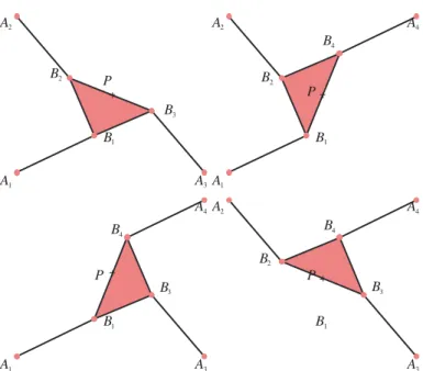
As the dimension of the wrench matrix W is four, we have four equivalent 3-RPR parallel mechanisms, as it is shown in Fig. 3. The cable robot is controllable as long as the four cables remain in positive tension. This is the case if none of the four equivalent 3-RPR manipulators cross a singular configuration. If we change the shape of the mobile platform and number of attachments k at the end-effector, then we have a great impact on the size and shape of the workspace.
5 In this paper, we will study the cases where k is equal to 2 (line platform), 3 (triangular) and 4 (rectangular).
A1 A3 A2 A4 B1 P B2 B3 B4
Figure 2: An example of a planar 4-4-cable robot.
A1 A3 A2 B1 P A1 A2 A4 B1 P B2 A1 A3 A4 B1 P B4 A3 A2 A4 B1 P B2 B3 B3 B4 B3 B4 B2
Figure 3: The four sub assembly for the planar 4-4-cable robot.
Definition of the geometric properties of the cases study and parallel singularities
For the following three examples, we fix the attachment points onto the base as [18]. Let A1 0 0T , 2 0
T y A l , 3 0 T x A l and 4 T x y A l l with Lx 6 and Ly 5.
Constraint equations can be expressed as 2 2 2 : ( ) ( ) i B i x B i y A i B i y B i x A i i E q x x y x y x x y l (14) for i1, ..., 4 and Bi [xB i yB i]T. Square mobile platform
Let B1 h1 h2, B2 h1 h2, B3h1 h2,
4 1 2
B h h in the local frame and h11 and h2 1. For the four 3-RPR robots the determinants of the Jacobian matrices are
2 1 2 2 : 6 0 1 5 6 1 1 3 0 3 0 0 y x x x y x y x y xy x y x y C (15)
2 2 2 2 : 55 5 1 5 5 6 11 30 30 0 y x x x y x y x y xy x x y x y C (16)
2 3 2 2 : 66 6 1 6 5 6 11 30 30 0 y x x x y x y x y xy y x y x y C (17)
2 4 2 2 : 61 11 31 5 6 5 6 11 30 30 0 y x x x y x y x y xy x y x y x y C (18)Values of Ci depend on the end-effector pose only, as it is
shown in Fig. 4.
Let P0 be defined as x3, y2.5 and 0, then 13
C , C2 3, C3 3 and C4 3. As P0 and 0 represents a stable pose for the cable robot, we know that the workspace W is defined up to the first singularity of at least one 3-RPR manipulator.
1 2 3 4 0 fo r 1 ...4 , , , / 0 an d 0 an d 0 an d 0 i x y E q i x y W C C C C (19)Figure 5 represents the same information as Fig. 4, but the workspace is characterized by a set of cells obtained by the CAD. This result can be obtained by using the
CellDecomposition function of Maple and depicted with PlotCell function for planar cases. The PlotCell3D function was
implemented in Maple for this paper. This function has been extended to define the cells for spatial cases.
Figure 6 represents the workspace described by 21 cells from 5758 cells obtained with the CAD decomposition. The borders represent the parallel singularities.
y
x
0 1 2 3 4 5 6
5
4
3
2
1
0
5
4
3
2
1
0
0 1 2 3 4 5 6
y
x
0 1 2 3 4 5 6
5
4
3
2
1
0
y
x
y
x
5
4
3
2
1
0
0 1 2 3 4 5 6
Figure 5: The workspace for the square mobile platform robot in Figure 2 for 0 and 0.04 with S(0 )1 2,S(0 .0 4 )5 .7 2.
Figure 6: The workspace for the square mobile platform robot in Fig. 2 with S(0 )1 2, S(0 .0 4 )7 .3 2.
Triangular mobile platform
Let us consider the cable-robot with triangular mobile platform in Fig. 7 having B1 h1 h2, B2 B4 0 h2 and
3 1 2
B h h in the local frame with h11 and h21. Singularity conditions can be expressed as
2 1 2 2 2 2 2 : 6 30 3 3 8 4 45 30 5 3 3 3 3 15 4 3 15 0 y y y y x y x y x y y y x x x x x x x y y xy x y x x y y x x yx y y C (20) 2: (x 5 y)(1 yx 2xx 2yyxy)0 C (21) 2 3 2 2 2 2 2 : 5 3 6 3 8 4 3 6 3 0 1 2 * 3 1 8 3 3 4 3 3 2 1 3 9 0 y y x y y x y x y y y y x x x x x x x x xy y x y x y x y x y xy y y C (22) 4: ( 5 ) ( 1 12 2 2 6 ) 0 x x x x y y y y x y x y C (23)
The values of Ci depend on the pose of the end-effector
only, as it is shown in the examples of Figs. 8 and 9.
Figure 10 represents the workspace described by 21 cells from 5758 cells obtained with the CAD decomposition.
A1 A3 A2 A4 B1 P B2 B3
Figure 7: An example of a planar 3-4-cable robot.
y
x
0 1 2 3 4 5 6
5
4
3
2
1
0
5
4
3
2
1
0
0 1 2 3 4 5 6
y
x
Figure 8: The singularity curves Ci for 0 and 0.04
0 1 2 3 4 5 6
5
4
3
2
1
0
y
x
y
x
5
4
3
2
1
0
0 1 2 3 4 5 6
Figure 9: The workspace for 0 and 0.04 for the triangular platform robot in Fig. 7 with S(0 )7 .5,S(0 .0 4 )7 .3 2.
7 Line mobile platform
Let us consider B1 B3 0 h and B2 B4 0 h
expressed in the local frame with h 1, as it is depicted in Fig. 11.
For the four 3-RPR manipulators, determinants Ci of the
matrices are 1: (y-x)(xx 5y yy)0 C (24) 2: (y 5 x)(xx yy)0 C (25) 3: (y-x)(6xxx 5y yy)0 C (26) 4: (y 5 x)(xx 6x yy)0 C (27)
It is worth to note that in this case left terms of C1 and C3, (resp. C2 and C4) are the same. Values of Ci depend on the
pose of the end-effector only, as it is shown in Fig. 12. Singularities occur wheneverA1,B1,B2 and A2 are aligned (resp.A3,B1,B2 and A4).
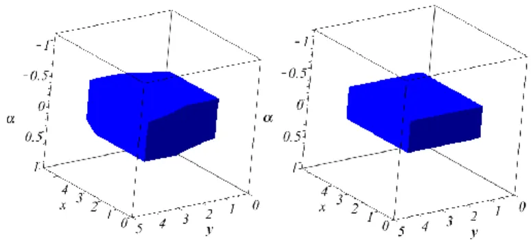
Figure 13 shows the workspace of the cable-robot with line platform when 0and 0.04. The complexity of the CAD depends on the order of the parameter in which we realize the projection. For the three cases, the simplest one is
y x. The CAD yields 330 cells but only six represent the intervals in which Pt0 y0 x0 is associated to a stable pose of the cable robot, as is shown in Fig. 14.
A1 A3
A2 A4
B1
P B2
Figure 11: An example of a planar 2-4-cable robot.
y
x
0 1 2 3 4 5 6
5
4
3
2
1
0
5
4
3
2
1
0
0 1 2 3 4 5 6
y
x
Figure 12: The singularity curves Ci for 0 and 0.04.
0 1 2 3 4 5 6
5
4
3
2
1
0
y
x
y
x
5
4
3
2
1
0
0 1 2 3 4 5 6
Figure 13: The workspace for 0 and 0.04 for the line platform robot in Fig. 11 with S(0 )1 8, S(0 .0 4 )1 7 .2 3.
Figure 14: The workspace for the line mobile platform.
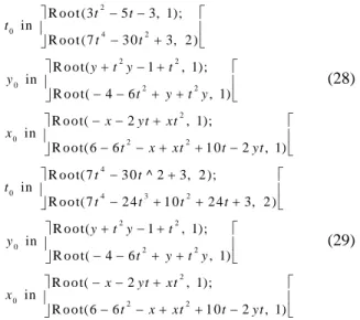
For example 2
R o o t (3t 5t3, 1) means the first real root of 2
3t 5t3. The CellLocation function permits to known in which cell is located one pose. So we can easily test the feasibility of one task.
2 0 4 2 2 2 0 2 2 2 0 2 2 R o o t (3 5 3, 1); in R o o t (7 3 0 3, 2 ) R o o t( 1 , 1); in R o o t( 4 6 , 1) R o o t( 2 , 1); in R o o t(6 6 1 0 2 , 1) t t t t t y t y t y t y t y x yt xt x t x xt t yt (28) 4 0 4 3 2 2 2 0 2 2 2 0 2 2 R o o t(7 3 0 ^ 2 3, 2 ); in R o o t(7 2 4 1 0 2 4 3, 2 ) R o o t( 1 , 1); in R o o t( 4 6 , 1) R o o t( 2 , 1); in R o o t(6 6 1 0 2 , 1) t t t t t t t y t y t y t y t y x yt xt x t x xt t yt (29)
4 3 2 0 4 3 2 2 2 0 2 2 2 0 2 2 R o o t(7 2 4 1 0 2 4 3, 2 ); in R o o t(7 2 4 3 0 2 4 3, 2 ) R o o t( 1 , 1); in R o o t( 4 6 , 1) R o o t( 2 , 1); in R o o t(6 6 1 0 2 , 1) t t t t t t t t t y t y t y t y t y x yt xt x t x xt t yt (30) 4 3 2 0 2 2 0 2 2 2 0 2 2 R o o t(7 2 4 3 0 2 4 3, 2 ); in R o o t( , 1) R o o t( 1 , 1); in R o o t( 4 6 , 1) R o o t( 2 , 1); in R o o t(6 6 1 0 2 , 1) t t t t t t y t y t y t y t y x yt xt x t x xt t yt (31) 4 2 0 2 2 0 2 2 2 0 2 2 in R o o t( , 1); R o o t(7 3 0 3, 3) R o o t( 1 , 1); in R o o t( 4 6 , 1) R o o t( 1 0 2 , 1); in R o o t( 6 6 2 , 1) t t t t y t y t y t y t y x xt t yt x x xt t yt (32) 4 2 0 2 2 2 0 2 2 2 0 2 2 R o o t(7 3 0 3, 3); in R o o t(3 5 3, 2 ) R o o t( 1 , 1); in R o o t( 4 6 , 1) R o o t( 1 0 2 , 1); in R o o t( 6 6 2 , 1) t t t t t y t y t y t y t y x xt t yt x x xt t yt (33)
where t tan / 2. Moreover, this representation allows us to compute the area of each cell using the built-in integration functions of Maple. Indeed, the Maple procedure int can handle functions of the form f t( ) R o o t (pt(X), )n , that maps a real
t to the nth root of the polynomial pt(X) whose coefficients depend on t.
A WORKSPACE COMPARISON FOR THE DESIGN OF PLANAR 4-CABLE ROBOTS
Analysis
In the following a comparison among the workspaces for the planar 4 cable robots reported in the previous Section is given. In particular, the 4-4, 3-4 and the 2-4 designs have been analyzed. As expected, increasing the number of attachment points on the mobile platform, the orientation capability of the robot decreases, as it can be clearly seen by Figs. 6, 10 and 14 and Tab. 1. Moreover, the reported case of study for the 4-4 cable robot (square platform) shows a poor orientation
capability of the robot. The volume of the workspace cannot be use as a criterion to compare the cable robots. In Tab. 1, we have computed the area S of slicing of the workspace for
0
and 0.04.
Moreover, we can show a meridian slice to evaluate the orientation capability, as in Fig. 15 for x3, and as in Fig. 16 for y5 / 2 to obtain m in and m ax.
Let us suppose we want to design a cable-based parallel robot, with requirement of the user being to obtain a regular workspace (sphere, cylinder, cube, ..) for which the angular rotation range of the moving platform is defined. This request can be given as a set of constraints.
Table 1: Comparison of the properties of the three type of mobile platform
Shape of mobile platform Square Triangle Line
m in 0.0906 0 .4 6 3 0 .8 7 6 m ax 0.0906 0.463 0.876 ( 0 ) S 1 2 7 .5 18 (0 .0 4 ) S 7.32 7.32 1 7 .2 3 y -1 -0.5 0 0.5 1 0 1 2 3 4 5 -1 -0.5 0 0.5 1 y 0 1 2 3 4 5 -1 -0.5 0 0.5 1 y 0 1 2 3 4 5 (a) (b) (c)
Figure 15: The workspace for x3 for (a) a square, (b) a triangle, (c) a line mobile platform.
x -1 -0.5 0 0.5 1 0 1 2 3 4 5 -1 -0.5 0 0.5 1 0 1 2 3 4 5 x -1 -0.5 0 0.5 1 0 1 2 3 4 5 x (a) (b) (c) Figure 16: The workspace for y2.5 for (a) a square, (b) a
triangle, (c) a line mobile platform.
For a cylindrical shape workspace, we can use a cylinder toped by two planes or an approximation by a Lame’s curve.
9 For example, Eq.(34) (resp. Eq.(35)) approximates a cylinder
(resp. a cube), where cx, cy and c are the geometric centre coordinates and lxand ly are the radius of the cylinder if lx=ly
and its depth (resp. the sizes of a cube).
2 2 20 1 0 y x x y y c x c c l l (34) 20 20 20 1 0 y x x y y c x c c l l (35)
These constraints can be included when we compute the workspace. If we obtain a workspace smaller than expected, it means that the cable robot has singular configurations within the requested regular shape workspace. Then we have to change the design parameters.
Fig. 17 shows the approximated cylindrical and cubic shaped workspace by Lame’s curves. Figure 17 shows the maximal value of that we can reach when lx 4 and
3
y
l .
Figure 17: The approximation of a cylinder and a cube by Lame’s curves to approximate a regular workspace.
Figure 18: The intersection of a cubic regular workspace with the workspace made by a line mobile platform for (a)
0 .7 8
and (b) 0 .5, lx 4 and ly 3.
Over-constrained manipulators
Let us consider the above-mentioned planar 4-cable
manipulator, which is a fully-constrained robot having 3 DOFs in the plane, if we add a 5th cable, then we get an over-constrained manipulator. This means that we admit that the tension in one cable can have no positive value.
In this case, we have to study the workspace of cable-based parallel robot taking into account four cables only. For each one, we will have four constraints Ci to define the border of the
workspace W. If we have Ci 0 for a stable pose for 1, ..., 5
i , the workspace can be defined as the following
1 2 3 4 1 2 3 5 1 2 4 5 1 3 4 5 2 3 4 5 , , , / 0 fo r 1 ...5 0 an d 0 an d 0 an d 0 o r 0 an d 0 an d 0 an d 0 o r 0 an d 0 an d 0 an d 0 o r 0 an d 0 an d 0 an d 0 o r 0 an d 0 an d 0 an d 0 x y i x y E q i C C C C W C C C C C C C C C C C C C C C C (36) CONCLUSIONSA new method was introduced to compute workspace of the general 4-cable robot by algebraic tools. We obtain automatically the algebraic formulation of the boundary of the workspace first described in [21]. Furthermore, our approach can be generalized to higher dimension and other type of constraints. Contrary to methods based on discretization of the workspace or the interval analysis based method, we obtain an exact formulation of the boundary of the workspace. For the same location of the attachment points, we have compared the size of the workspace and the angular rotation range for several types of mobile platforms. When the shape of the mobile platform is a line, the equations representing the workspace boundary were simple and the angular rotation range was the greatest.
The proposed method provides a powerful tool to analyze fully-constrained planar or spatial cable-robots as an extension of the proposed formulation, which will be developed as future work. Furthermore, it may allow the analysis of the over-constrained manipulators, for which the number of cables is greater than the number of DOFs + 1. For the latter case, the analysis can be performed by recursively applying the described method, providing all possible combinations of sub-assembly manipulators, the workspace being the union of the computed sub-workspaces.
ACKNOWLEDGEMENTS
The research work reported here was made possible by SiRoPa ANR Project.
REFERENCES
[1] Roberts, R.G., Graham, T., Lippitt, T., 1998. “On the inverse kinematics, statics, and fault tolerance of cable-suspended manipulators”, Journal of Robotic Systems 15 (10), pp. 581–597. [2] Ottaviano, E. and Castelli, G., 2010, “A Study on the Effects of
Cable Mass and Elasticity in Cable-Based Parallel Manipulators”, Proc. f the18th CISM-IFToMM Symp. On Robot Design, Dynamics and Control, Springer Ed. Udine, pp.149-156.
[3] Castelli, G, Ottaviano, E, González, A, 2010, “Analysis and simulation of a new Cartesian cable-suspended robot”, Proc. IMechE 224 Part C: J. Mech. Engineering Science, pp. 1717-1726. [4] Fattah, A., and Agrawal, S. K., 2005, “On the design of
cable-suspended planar parallel robots”, ASME Journal of Mechanical Design, 127 (5), pp. 1021-1028.
[5] Verhoeven, R., 2004, “Analysis of the Workspace of Tendon-based Stewart Platforms”, PhD thesis, University of Duisburg-Essen. [6] Wischnitzer, Y., N., Shvalb, Shoham, M., 2008, “Wire-driven
Parallel Robot: Permitting Collisions between Wires”, The International Journal of Robotics Research, 27 (9), pp. 1007-1026. [7] Bruckmann, T., Mikelsons, L., Brandt, T., Hiller, M., Schramm, D.,
2008, “Wire Robots Part I Kinematics, Analysis & Design”, in Ryu J.-H. “Parallel Manipulators, New Developments”, I-Tech Education and Publishing, Vienna.
[8] Riechel, A., Ebert-Uphoff, I., 2004, “Wrench-based analysis of cable-driven robots”, Proc. of IEEE International Conference on Robotics and Automation, New Orleans, pp. 4950–4955.
[9] Barrette, G., Gosselin, C.M., 2005, “Determination of the dynamic workspace of cable-driven planar parallel mechanisms”, ASME Journal of Mechanical Design, 127 (2), pp. 242–248.
[10] Pham, C.B., Yeo, S.H., Yang, G., Kurbanhusen, M.S., I-Ming, C., 2006, “Force-closure workspace analysis of cable-driven parallel mechanisms”, Mechanism and Machine Theory, 41, pp. 53–69. [11] Diao X., Ma O., 2007, “A method of verifying force-closure
condition for general cable manipulators with seven cables”, Mechanism and Machine Theory, 42, pp. 1563–1576.
[12] Lafourcade, P., Llibre, M. and Reboulet C., 2002, “Design of a Parallel Wire-Driven Manipulator for Wind Tunnels”, in Proc. of Workshop on Fundamental Issues and Future Research Directions for Parallel Mechanisms and Manipulators, Quebec City, pp. 46-56. [13] Kawamura, S., Kino, H., Won, C., 2000, “High-speed manipulation
by using parallel wire-driven robots”, Robotica, 18 (1), pp. 13-21. [14] Moroz, G., Chablat, D., Wenger P., Rouiller F., 2010, “Cusp points
in the parameter space of RPR-2PRR parallel manipulator”, 3-rd European Conference on Mechanism Science, Cluj-Napoca, Romania September 14-17, pp. 29-37.
[15] Chablat D., Moroz G. , Wenger P., “Uniqueness domains and non singular assembly mode changing trajectories”, Proc. IEEE Int. Conf. Rob. and Automation, Mai 2011.
[16] Cox D., Littleand J., O’Shea, D., “Ideals, Varieties, and Algorithms”, Undergraduate Texts in Mathematics, Springer Verlag, 1992.
[17] Chablat D., Wenger Ph., “Working Modes and Aspects in Fully-Parallel Manipulator”, Proceeding IEEE International Conference on Robotics and Automation, pp. 1964-1969, May 1998
[18] Ebert-Uphoff, P.A. Voglewede, 2004, “On the connections between cable-driven manipulators, parallel manipulators and grasping”, in: Proc. of IEEE Int. Conf. on Rob. & Auto., New Orleans, pp. 4521–4526.
[19] McColl, D. and Notash, L., 2010, “Workspace Generation of Planar Wire-Actuated Parallel Manipulators with Antipodal Method”, Proc. f the18th CISM-IFToMM Symp. On Robot Design, Dynamics and Control, Springer Ed. Udine, pp. 291-298.
[20] Azizian, K., Cardou, P., Moore, B., 2010, “On The Boundaries of the Wrench-Closure Workspace of Planar Parallel Cable-Driven Mechanisms”, Proc. of the ASME 2010 Int. Des. Eng. Tech. Conf. & Comp.and Inf.in Engi. Conf. IDETC/CIE 2010, Montreal, paper DETC2010-28135.
[21] Gouttefarde, M., and Gosselin, C., 2004. “On the properties and the determination of the wrench-closure workspace of planar parallel cable-driven mechanisms”. In ASME International Design Engineering Technical Conferences, pp. 337–346.
[22] Gouttefarde M., and Gosselin C. M., 2006, “Analysis of the wrench-closure workspace of planar parallel cable-driven mechanisms”, IEEE Transactions on Robotics, 22 (3), pp. 434-445.
[23] Gouttefarde, M., Merlet, J.-P., and Daney, D., 2006, “Determination of the wrench-closure workspace of 6-DOF parallel cable-driven mechanisms”, Advances in Robot Kinematics (ARK), J. Lenarcic and B. Roth eds., Springer, pp. 315-322.
[24] Stump, E., and Kumar, V., 2006, “Workspaces of cable-actuated parallel manipulators”, ASME Journal of Mechanical Design, 128 (1), pp. 159-167.