Digital Cockpits and Décision Support Systems
Design of Technics and Tools to Extract and Process Data
from Heterogeneous Databases
Mémoire présenté
à la Faculté des études supérieures de l'Université Laval dans le cadre du programme de maîtrise en informatique pour l'obtention du grade de Maître es Sciences (M.Se.)
FACULTÉ DES SCIENCES ET DE GENIE UNIVERSITÉ LAVAL
QUÉBEC
2006
A mes parents, mes soeurs, mes frères, et à toute ma famille... Je dédie ce travail
Acknowledgment
I would like to sincerely thank my supervisors Dr. M.Debbabi and Dr N.Tawbi for their constant support, precious help and advice. I would only be restating the obvious when I say that they are great advisors. I hâve learnt a lot from them, and I consider myself truly fortunate to hâve them as my advisors and thank them for the opportunity to work under their guidance.
I would like to thank Dr. M.Mejri for his acceptance to evaluate my work and for his valued évaluation and remarks.
In thèse few lines, I should not forget my parents, sisters, brothers, and ail my family for their continuous support.
Lastly, I thank ail those who hâve, directly or indirectly, contributed in the achieve-ment of this work and my success.
Résumé
Ce travail présente une nouvelle approche pour l'intégration des systèmes d'information. Cette approche permet d'intégrer des systèmes hétérogènes en matières de : modèles de données, systèmes d'opérations, reseaux utilisés, etc. pour fournir enfin aux décideurs ou/et utilisateurs une information à jour et consistante qui sera la base de décisions cor-rectes et fiables dans le processus décisionnel. Principalement, notre méthodologie est une approche multi-couche: une couche intégration des différentes sources de données, une couche fournit un service de messagerie qui envoie l'information provenant des différentes sources aux différents clients intéressés dans cette information, et une autre consiste en une application client. La première couche vise à connecter les différentes bases de données en éliminant les différences spécifiques à chacune de ces dernières. La seconde, service de messagerie, permet d'envoyer l'information aux multiple utilisa-teurs dans un mode asynhrone, ce qui libère l'application client de rester couplée avec la source de données et en même temps garantit la délivrance de cette information à ses abonnés. Pour la couche "application client", elle est responsable de : l'affichage et la présentation de l'information reçue à partir de l'intergiciel basé sur le service de messagerie; de la mise à jour en temps réel de l'affichage en reflétant l'état présent des sources de données; ainsi que d'autres processus de control et d'optimisation.
Notre intergiciel, proposé au sein de cette thèse, est basé sur un ensemble d'APIs standards (surtout celles provenant du monde J2EE) ce qui lui offre une large interop-érabilité et facilité d'extension.
Abstract
This work présents a new approach for integrating information Systems. This approach allows Connecting Systems that are heterogenous in terms of: data models, operating Systems, used networks, etc. It ultimately provides décision makers or/and users with up-to-date, consistent and well presented information which will be the basis of correct and reliable décisions in the décision making process. Primarily, our intégration modus operandi is a multi-layer approach: an intégration connection layer, a messaging service layer, and a client application layer.
The first one aims at Connecting the various databases by eliminating the différences that are spécifie to each one. The second, messaging service, allows to push informa-tion incoming from the multiple sources to customers interested in this informainforma-tion in an asynchronous mode. It releases the customer application to remain coupled with the data source, and at the same time guarantees the delivery of this information to différent subscribers. The third layer, client application, is responsible for: display and présentation of information received from the messaging layer; real-time updating of display to reflect the state of the data sources; and other control and optimization procédures.
Our middleware, proposed within this work, is platform, OS, and DBMS indepen-dent. It is based on a set of standard APIs (especially those coming from J2EE world) which offers broad interoperability and provides easy extensibility.
Contents List of Tables List of Figures 1 Introduction 1.1 Motivation 1.2 Objectives 1.3 Contributions 1.4 Document Structure
2 Enterprise Application Intégration and Décision Support Systems
2.1 Introduction
2.2 Application Intégration 2.3 Information Intégration
2.3.1 Materialized Views
2.3.2 Federated Architecture Solution 2.4 Business Processes Intégration
2.4.1 Tasks Executed by an Internai Process 2.4.2 Advantages of Business Process Intégration 2.5 Portai Oriented Intégration
2.5.1 Portais Rôle
2.5.2 Advantages and Limitations of Portai Oriented Intégration . . . 2.6 Service Intégration
2.6.1 Web Services
2.6.2 XML: A Big Step for an Unlimited Interoperability 2.6.3 Web Services Model
2.6.4 Web Services Stack 2.7 Messaging Service
2.7.1 Types of Middleware
2.7.3 Classification of Messaging Service 2.7.4 Java Message Service
2.7.5 JMS Properties
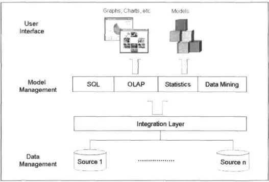
2.8 Décision Support Systems and Digital Cockpit 2.8.1 Décision Support Systems
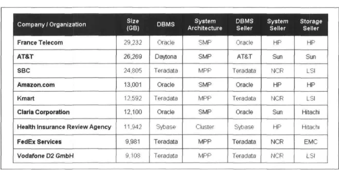
2.8.2 Data Explosion Phenomenon 2.8.3 Digital Cockpits
2.9 Conclusion
3 Digital Cockpit Architecture
3.1 Introduction
3.2 General Description
3.3 Layer-based Intégration Approach 3.3.1 Phase 1: Unified Framework 3.3.2 Phase 2: Messaging Service 3.3.3 Phase 3: Client Application 3.4 Digital Cockpit Artchitecture
3.5 Extending Digital Cockpit Architecture: Service Intégration 3.6 JMS/RPC-based Middleware Comparison
3.7 Scope and Limitations
4 Digital Cockpit Implementation
4.1 Introduction
4.2 Software Requirements 4.2.1 House of Quality 4.2.2 Domain Model 4.2.3 Use Case Model 4.3 Software design
4.3.1 Assumptions and Policies 4.3.2 Methodology
4.3.3 Important Class Diagrams 4.4 Implementation
4.4.1 Technology 4.4.2 User Interface 4.5 Conclusion
5 Conclusion
A Digital Cockpit Use Cases List B Class Diagrams
C Challenges and Technology Choice D List of Used Acronyms
2.1 Federated Architecture Vs Data Warehousing Approach 4.1 Advantages of Digital Cockpit Solution
C l Technology Stack of Digital Cockpit Implementation . C.2 Technology Stack of Digital Cockpit Implementation . C.3 Technology Stack of Digital Cockpit Implementation .
2.1 Enterprise Application Intégration (EAI) 2.2 Data Warehouse Architecture
2.3 Federated Architecture for Data Intégration 2.4 TSMMIS Architecture
2.5 Portai Intégration 2.6 Web Services Rôles 2.7 Web Services Stack 2.8 JMS Messaging Model 2.9 Data Explosion Example 2.10 Generic DSS Architecture 3.1 Layer-based Approach 3.2 Intégration Model 3.3 Detailed Architecture
3.4 Architecture of Service Intégration
3.5 Retrieval of information for Single Client Application 3.6 Multiple Clients Requesting the Middleware
3.7 Notification Mechanism: Comparison 4.1 House of Quality: Digital Cockpit Project 4.2 Domain Model: Digital Cockpit Project 4.3 Use Case Model: Digital Cockpit Project
4.4 Séquence Diagram of Display Module: Digital Cockpit Project 4.5 Digital Cockpit 5-Phases Paradigm
4.6 Display Class Diagram 4.7 Display User Interface
4.8 Digital Cockpit Analysis Example 4.9 Digital Cockpit Simulation Example
4.10 a)The overall view of Weather Scénario b)Interested user drills down in detailed information c) A spécifie weather component: Wind forecast . B.l Class Diagram: Integrator Module
Introduction
1.1 Motivation
In the last décade, tremendous advances occurred in computers performance, commu-nication infrastructures, storage technologies, and middleware applications. Ail thèse achievements hâve made from information Systems the cornerstone that shapes the présent and the future of our economy and society. Tins omniprésence of computers in ail aspects of our life has been fuelled by the explosion of Internet. This explosion with the reliability of communications were -and still- behind the new business initiatives such as e-business and e-commerce.
Today's enterprises and organizations use a large variety of networked computer Systems and software applications to collect, process and produce large volumes of data. The ability to turn thèse islands of data into useful knowledge (information that can be used by décision makers) provides industries with a compétitive advantage in their mission-critical situations. Décision makers, top management and leaders need robust, efficient and automatic tools to sensé and respond to real-time changes.
However, such an undertaking is not a small task. Enterprise Systems are dis-parate in terms of hardware, platforms, operating Systems and software applications. Moreover, thèse Systems extend beyond the firewall to include partners, suppliers, and customers. As a resuit, extracting critical nuggets of information from thèse heteroge-neous, autonomous, and physically distributed Systems présents a challenging problem for today's research communities and businesses.
the barriers revealed above. Such software platforms should be able to:
• Provide a structured, regular and real-time communication of fresh information inside and across the organization's boundaries.
• Keep synchronized and cohérent multiple databases.
• Produce status and analysis reports on différent activities/processes.
• Scrutinize to the desired level past, ongoing and future activities/processes. • Handle the needed security services in terms of authentication, secrecy,
autho-rization and integrity.
• Présent to a given decision-maker or a principal the information in a graphical and user-friendly way.
As a downstream resuit, a décision maker will hâve a realtime big picture that intégrâtes ail the needed information to make an educated, solid and sound décision.
1.2 Objectives
The aim of this work is to propose the design of a distributed software platform (mid-dleware and the underlying applications) that is referred to Digital Cockpit paradigm. The intent of the digital cockpit is twofold: At first, it achieves a synergistic intégration of the various information Systems. Secondly, the digital cockpit will display visual, structured, navigational and realtime big pictures, so that décision makers can drill down into the détails and uncover relationships between information that might other-wise remain hidden. Consequently, the décision making process can be enhanced using the available information [7].
More explicitly, we can classify the objectives of our work in the following points:
• Identify the différent information and service sources of the organization and the underlying databases, data models, formats and protocols.
• Integrate, in a synergistic way, ail thèse sources of information in order to ensure a real-time availability of updated, Consolidated, structured and unified data across the network.
• Elaborate a digital cockpit platform that will présent the synthesized informa-tion through dynamic and real-time visual objects. Moreover, the digital cockpit should offer the possibility to customize the layout and the access privilèges ac-cording to différent user profiles.
• Propose a suite of procédures and tools that extract data from différent sources in order to subject them to business intelligence on-line analytical processing (statistical analysis, graphical techniques, simulation of what-if scénarios, trend analysis, comparative analysis, etc.).
By building a digital cockpit that meets the aforementioned objectives, we anticipate that the décision makers will hâve the capability to access, analyze and visualize data and services in order to take judicious and Consolidated décisions.
This work mainly describes the design and the implementation of a digital cockpit System; a prototype that shows the main functionalities of a décision making oriented middleware. Through this work, we will expose the différent steps to build such a middleware, from the intégration of simple data to visualization of critical nuggets of information as valuable business assets, that help significantly to enhance the décision making process.
1.3 Contributions
The following are the contributions of this work:
• Via our middleware, we are able to integrate a variety of data and services from heterogenous databases that are physically in différent locations.
• Our System provides a function that transforms the integrated data into a visual big picture that can help in understanding data and support décision makers to take educated and Sound décisions.
• The real-time capture of data changes in distant databases is indeed another functionality that can leverage managers with real-time monitoring of business events, and therefore react instantly accordingly.
As a whole, this work represents a new fashion for real-time information Systems intégration and décision support Systems based on a set of standard technologies, which provide an interesting opportunity for an easier and economical extensibility and scal-ability to the System.
1.4 Document Structure
This document is composed of five chapters. In Chapter 2, we présent Enterprise Appli-cation Intégration (EAI) and Décision Support Systems (DSS). Différent approaches of EAI, DSS and digital cockpit are introduced in this Chapter. In Chapter 3, we highlight the approach we are proposing to build a digital cockpit, as a new paradigm for real time information intégration and décision making. In Chapter 4, we détail the design and implementation of the digital cockpit including the architecture of our proposed middleware. Finally, in Chapter 5, we conclude with a summary and provide directions to future work.
Enterprise Application Intégration
and Décision Support Systems
2.1 Introduction
With the advent of the web and the increasing number of databases that each business or organization handles, the intégration of heterogeneous, autonomous, and geographically distributed data sources has become a major concern of Information Technology (IT) community.
Statistics show that information intégration is one of top priorities of Chief Infor-mation Officers (CIO) in almost every company [27]. Data intégration Systems aim to provide a uniform and transparent access to the aforementioned data sources. They differ according to the nature of the problem and the underlying field. Intégration ap-proach and used technologies are two main criteria that feature an intégration solution. The first one is from a design stand point; it coins to the followed methodology and the content to be integrated. However, the last one is concerned with the applied products. as application programming interfaces (APIs), used to translate the above design to a concrète implementation.
In this chapter, we présent first application intégration. After, we discuss the main intégration approaches and show where each approach fits better. We put more empha-sis on information and service intégration since they play a key rôle in our approach. Then, we highlight the messaging service as a communication style, détail existing messaging technologies, and describe Java Message Service (JMS) model, a Java-based
standard messaging API. Afterwards, we présent Décision Support Systems (DSS), their types and architecture. Finally, we introduce the "Digital Cockpit" concept as a new fashion to combine both of enterprise application intégration and décision support realms. This combination of the above two fields allows real-time information Systems intégration with décision support capabilities.
2.2 Application Intégration
Enterprise Application Intégration (EAI) pertains to the interconnection of information Systems, internai and/or external to the enterprise. This interconnection aims to a better sharing of data and application services. As a downstream resuit, intégration drives to an enhancement of information exchange, and therefore a real-time exécution of business processes [45].
The connected Systems may be an Enterprise Resource Planning (ERP), a Supply Chain Management (SCM), a Customer Relationship Management (CRM), or any other Enterprise Information System (EIS). Regardless of their heterogeneity, autonomy, and if they are on the same or on différent machines; Connecting thèse Systems together will leverage users and especially décision makers with an easy and transparent access to ail the information the enterprise retains. Figure shows a typical intégration problem.
°ifl*
ERP
Legacy Systems CRM
EAI Middleware Databases
Spécifie
Applications ThirdParty
Software ERP
SCM
Figure 2.1: Enterprise Application Intégration (EAI)
reflects the business needs of each organization. Accordingly, any intégration solution is business-requirements driven, and therefore, there is no universal and standard so-lution that can be applied for enterprises. Thus, each EAI soso-lution pursues a spécifie approach. However, the same intégration solution can combine several approaches, especially in big enterprises having complex and geographically distributed informa-tion Systems. Among the most prevailing approaches we fmd: Informainforma-tion Intégrainforma-tion, Business Process Intégration, Portai Oriented Intégration, and Service Intégration [45]. In the following sections, we présent thèse intégration approaches, the advantages and limitations related to each one.
2.3 Information Intégration
Information intégration [20, 68] is limited only to data. This approach allows companies to combine data from disparate data sources which are considered as the main points of connection. Intégration of data from multiple information sources is one of the longest standing problems facing the IT research community. In addition, being a problem in large corporations and organizations, research on this topic has been fuelled by the explosion of Internet. Therefore, for better information sharing, there is a real need to integrate the various and unlimited islands of data inside organizations and over the Web.
In this context, two main solutions [9, G7, 68] hâve been proposed for data intégra-tion: data warehousing (materialized views) and federated architecture (virtual views). Both approaches take a set of pre-existing decentralized data sources, and develop a single unified (mediated) schéma over them. Then, a séries of transformations or source mappings are specified to describe the relationship between each data source and the mediated schéma.
2.3.1 Materialized Views
Materialized views or warehousing solution requires the building of a data warehouse and writing programs that load data from data sources to the warehouse periodically. This task is achieved by the use of Extract, Transform and Load (ETL) tools. One of the most widely accepted définitions of a data warehouse is that given by Inmon [93]; a pionner in data warehousing technology.
Inmon, in his book [93], provides the following définition: "a warehouse is a subject-oriented, integrated, time variant, and non-volatile collection of data in support of management's décision making process". First, the data warehouse is subject oriented means that it is organized around the high-level entities of the business. In marketing for example, subjects are customers, products, and sales. Second, it is integrated because it intégrâtes data from différent sources, and might be inconsistent, so thèse data must be stored in a consistent format (naming conventions, data constraints, etc.) to provide a unified view to the users. Time variant means data are valid at a point of time or during a time interval. Finally, non-volatile signifies that data do not change in real-time in the warehouse, but refreshed periodically from productions databases. In other words, a data warehouse is a separate database, able to support management decision-making and receiving data from multiple operational data sources. Figure shows a simplified data warehouse architecture.
Reportmg
Analysis Data Mining
Data Warehouse
U
Warehouse Metadata
Extract Transform Load
ïï
Network
I
xr
_L_
Transactional
Data RDBMS LegacyApplications; SQL
Figure 2.2: Data Warehouse Architecture
Operational Data corne from a variety of sources including transactional data from mainframes, relational data from multiple RDBMS databases, and other production's databases. The ETL phase, called also data staging [64] aims at:
• First, pull out data from operational databases and place them into another data-base.
• Second, apply a séries of transformations on the extracted data to check their validity and accuracy, and résolve différences in syntax and semantics to conform with the new target database.
• Third, once data are extracted and transformed, it is time to write the new data into the target data warehouse, after carrying out appropriate summarizations and aggregations.
• At the end of this step, data should be detailed (no summarization yet), historical (allows historical values), and normalized (3rd normal form or higher), in such a way that supports decision-making [64].
Afterwards, the data warehouse is used by Online Analytical Processing (OLAP) applications and tools to run complex queries of large multidimensional collections of data, with an intent to assist managers and décision makers. Other kinds of tools may be supported by data warehouse such as data mining and data analysis based tools.
Below, we présent the major advantages and limitations of materialized views solu-tion for data intégrasolu-tion.
Advantages and Limitations
The data warehouse approach is relevant when data do not change frequently or when the integrated view does not need to be up-to-date. In addition, the warehouse is built specifically to enhance décision making, by crating a new database being accessed by différent kinds of data analysis tools like OLAP and data mining tools. Hence, the warehouse represents the well appropriate approach for analysis of historical data, extrapolation, and supporting stratégie décisions. Also, the séparation of the warehouse from operational data gives a good performance for the analysis tools.
However, building, entertaining, and refreshing the warehouse -with ETL tools- is costly and time consuming [?]. The differed updating of the warehouse, also does not play in favor of this strong technology in a world attempting to reach real-time business.
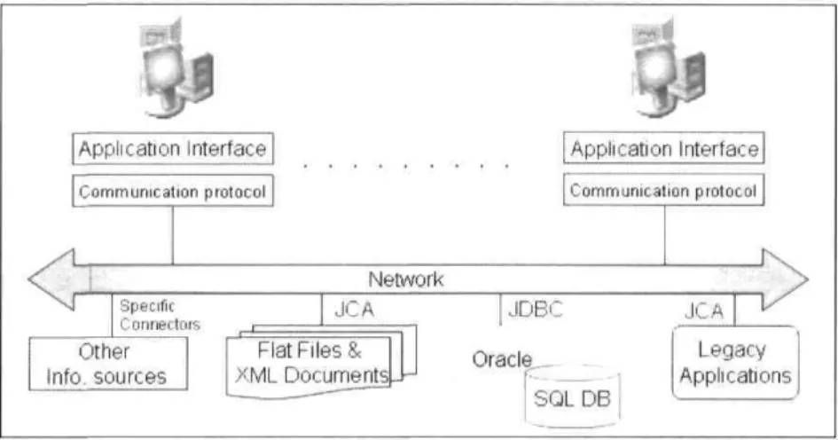
2.3.2 Federated Architecture Solution
Alternatively, in the federated architecture approach, also known as médiation approach for data intégration [4,'i] (the mediator used as a connector between multiple databases in
the federated approach for data intégration), we define one or more mediated schémas, which are not used for storing data but only for querying it. When a query is issued to the System, it is translated into a set of sub-queries, over the data sources, having the same semantic as thèse target data sources. This approach keeps the local autonomy of data sources and créâtes a virtual repository enabling real-time on-demand data access. Moreover, it addresses the case when data change frequently, or when the global schéma itself may change usually. Figure shows a simplified federated architecture for data intégration. Application Interface Communication protocol i (Application Interface Communication protocol J Network Spécifie Connectais JCA Other Info, sources j JDBC Oraclç.__ SQTDB JCA Legacy Applications
Figure 2.3: Federated Architecture for Data Intégration
A surge of interest has been expressed in data intégration by médiation approach, and many research projects hâve implemented this concept. Among the pioneer projects in this area we refer to TSIMMIS [74], Garlic [80], and DataJoiner [90].
First, TSIMMIS [30, 74] assumes a médiation approach to integratc both hetero-geneous, structured and unstructured information from multiple data sources. It uses wrappers to convert information into a cornmon object model. The intent of TSIMMIS is to provide décision makers with a tool that can get and fuse information from mul-tiple sources on need and keeping data their consistency. TSIMMIS puts a translator on top of each information source. This wrapper converts the underlying data objects into a common object model. When receiving a query, the wrapper translates it into the common model that the source can understand and exécute. Similarly, it converts the returned resuit into the common model. Figure is a simplified représentation of TSIMMIS architecture for data intégration.
2The Stanford-IBM Manager of Multiple Information Sources: a joint project between Stanford University and IBM Almaden Research Center
3 A project developed by members of the database group in Computer Science, IBM Research Center to enable large-scale multimédia information intégration
j Application Interface
Queryt 1 Resuit
H
Mediator
Wrapper Wrapper
Data Source 1 Data Source 2
Wrapper
Data Source n
Figure 2.4: TSMMIS Architecture
Second, Garlic solution for data intégration also relies on médiation approach and is developed in Garlic [86] project. Garlic aims to develop a multimédia information System that intégrâtes data from multiple information sources. Thèse data include différent types such as text, images, audio, video and other types. Garlic provides an object-oriented schéma to applications, interprets queries, defines exécution plans and returns queries results to the applications.
Finally, at the same tirne, another project called DataJoiner was being developed by IBM research team. Its main objective was to develop robust and efficient queries over a set of relational data sources
As cited previously, while DataJoiner was meant to integrate relational databases, Garlic's main goal was how to extend such a solution for a large set of heterogeneous information sources. At the end, both of thèse projects played a key rôle in defining functions to federate data sources with IBM DB2/DBMS [43].
For commercial tools in data fédération, we can refer to DiscoveryLink from IBM[42] and Attunity Federate from Attunity [5], etc. DiscoveryLink allows visualization of multiple distributed data sources to provide a single virtual schéma for use by the biologists. As for Attunity Federate, it is a federated solution that provides real-time access to heterogeneous data, both for querying and updating purposes. It also captures changes in data sources, so intégration can be accomplished in near real-time (Attunity Stream).
To recapitulate, information intégration through federated architecture is getting widely used especially with the increasing number of heterogeneous data sources and the need for real-time solutions for data intégration. Hereafter, we présent the advantages and limitations of this solution.
Advantages of Federated Architecture
The federated architecture for data intégration possesses the following features:
• Local autonomy of the integrated sources: Allows to avoid problems related to management of thèse sources since their is no change in data sources management and administration.
• Real-time intégration: Créâtes a virtual layer on top of data sources, which enables real-time and on demand access to up-to-date data. This feature is well suitable for today's business needs.
• Transparency: Provides the user with the query resuit s in a transparent way. It masks ail the data sources différences and complexities from the user.
• Extensïbility: Allows easily adding of new data sources in a dynamic way to meet new business requirements.
Selecting Data Intégration Approach
As stated above, the information intégration is a complex problem for ail IT community, and there is no standard and universal solution to this problem. Depending on the scope and the complexity of the intégration problem (from simple connection of two local databases to complex intégration of multiple heterogenous information sources geographically in différent locations), there are many issues to consider and assess when selecting an intégration approach [77].
• Degree of data update or change: What is the frequency of updating data, and does the data source updated by a single or multiple applications?
• Latency: How does data intégration occur? Is it done periodically using batch opérations such as in data warehouse, or in real-time as in federated architecture.
• Degree of cleansing and transformation: Are data clean and ready to be directly useful without or with minimum effort of cleansing and transformation?
• Real-time or Stratégie décisions: Are data sources used to react in real-time to business events or to prépare stratégie business décisions with an extensive use of historical data.
• Budget and resource constraints: Does the accorded budget for the intégration problem abide with the création of new physical databases or just for putting a wrapper over the existing data sources.
• Time-to-market requirements: The needs for data intégration solutions differ ac-cording to time-to-market constraints. For example, building a data warehouse solution needs planning and building, contrary to federated architecture.
• Transactions management: Is transactions management important for the inté-gration problem? If so and the data source can participate in transactions, the federated architecture may be considered.
In a nutshell, hère are the most important parameters that influence the sélection of a data intégration solution: the number of data sources, their heterogeneity, the volume of data to integrate, the business requirements such as real-time or differed, the needs for a high level of transactions management, and the financial constraints.
In Table , we provide a summary of the main features and différences between materialized views and federated architecture solutions for data intégration [77].
Information Intégration Ap-proach
Real-Time events notification Fréquent changes in data sources Stratégie décision support
Easy extensibility Easy access Short time-to-market Economical solution Federated Architec-ture
V
V
-V
V
Data Warehouse-Table 2.1: Federated Architecture Vs Data Warehousing Approach
After this review of the state of the art in data intégration, we présent briefly below, the most important APIs provided by Java world.
Java Technology for Data Connection
Java products oriented data connection become defacto standard for almost ail DBMS providers and large community of developers. Thus, Java Database Connectivity (JDBC) and J2EE Connector Architecture (JCA) are Java standard for Connecting multiple in-formation sources.
Java Database Connectivity (JDBC)
JDBC is an API provided by Java Sun within the Java Community Process (JCP) to leverage a standard API enabling connection of ail relational databases and spreadsheets such as Ms Excel. Majority of application servers provide support for JDBC [81].
J2EE Connector Architecture (JCA)
The resuit of a fruitful collaboration of most active software vendors (Sun, Oracle. IBM, BEA, etc.) through JCP, the spécification of JCA (Java Spécification Requests (JSR) 16 and 112) provides a standard Java technology solution to the problem of connectivity between the many application servers and today's enterprise information Systems. It enables vendors to create standardized connectors to EIS.
to sum up, federated approach is the most appropriate approach to achieve the intégration of many data sources. Supporting real-time business events notification plays in favor of this approach in case of big numbers of data sources, and distributed Computing environments where information sources are getting on and out. Therefore, in the rest of this document, we adopt the federated solution for data intégration to connect the différent databases related to our digital cockpit project.
2.4 Business Processes Intégration
In the previous section, we perceived that application intégration oriented data is only meant for data sharing purposes. This certainly enhances the information exchange between enterprises and businesses. However, this approach does not deal with business processes. This means that the définition of information flow has to be taken care by another approach: Business Process Intégration (BPI) [45]. Generally, the integrated Systems are autonomous; thus they hâve their own process choreography engines and therefore, run internai business processes private to them
The business process intégration defines a gênerai model for business processes that addresses the séquence, the hierarchy, the events, logical exécution and information transfer between Systems within the same organization (EAI), and between Systems from différent organizations (B2B ) [34]. The main idea behind business process inté-gration is to provide a single logical model that spans the multiple applications and data sources. Therefore, a single business process controls the interaction between humans and Systems to satisfy business requirements [45].
The business process intégration provides mechanisms that define and run the in-formation flow over multiple Systems [45]. It puts a logic control layer on the top of différent integrated technologies. This enables to connect local Systems into a single process that leverages the business opérations and objectives. This intégration approach should run this process in the correct order, with the appropriate information, with a control of séquences, keeping the state, durability, and possibility to handle exceptions
[45].
2.4.1 Tasks Executed by an Internai Process
In gênerai, an internai process exécutes many tasks to achieve the resuit expected by the gênerai process. First, the local System sends an event to a business process engine. Second, this engine transforms the event to be conform to certain semantic standards and mechanisms of information processing (synchronous or asynchronous). Afterwards, it reacts to the transformed event by invoking other processes from other Systems in favor of the exécution of a model, through the invocation of B2B processes. Then, the new local system (target) reacts to its internai processes and sends the answer to the business process engine. Finally, the gênerai model of the process controls the master process (on top of ail other processes) in order to enhance the B2B communication.
2.4.2 Advantages of Business Process Intégration
By defining a new layer above the source and target Systems, the business process intégration introduces many advantages:
• An instance of the new gênerai process spans many instances of internai processes spécifie to local Systems. This feature provides more visibility about the entire
activity.
• The independence of business process intégration from source and target Systems allows modifying processes without affecting the aforementioned Systems.
• The stratégie approach of business process intégration defines the business rules that détermine the interactions between Systems, in a common abstract business model.
• The définition of a common abstract business model provides the capability for real-time analysis of ail aspects of business, and allows determining the state of the process at any time.
• The ability to redefine the process any moment to enhance the efnciency, hide the complexities of local applications, and allow users working with the same business semantic.
2.5 Portai Oriented Intégration
The other approach in the application intégration stack is Portai Oriented Intégration.
2.5.1 Portais Rôle
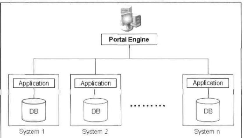
Portais allow viewing a multitude of Systems -both internai and/or external enterprise Systems- through a single user interface or application. They extend the user interface of each System to a common aggregated user interface. Therefore, they connect multiple Systems although they do not directly integrate the applications within or between the enterprises. Via portais, the user interacts with the back end Systems through a user interface -such as a web browser-, rather than having the Systems automatically ex-change the information (as in data oriented intégration). The intégration using portais approach can be achieved along many technologies: application servers, page servers (ASP, PHP, JSP,etc), and screens conversion technologies into HTML, etc. Today, more B2B information flow through the user interfaces (portais) than automatically through back end intégration. The figure - shows how portais allow retrieving infor-mation from multiple applications in a unified user interface.
| Application | i Portai Engine | Application
X
[
DB Application DBSystem System 2 System n Figure 2.5: Portai Intégration
2.5.2 Advantages and Limitations of Portai Oriented
Intégra-tion
Portais allow users to interact with a company's internai system through a user interface (generally a web browser). They are typically much easier to build than sophisticated and real-time intégration, the case of data and process intégration. In addition, portai intégration approach can be easily added to existing Systems without disturbing the existing functionalities [44]. Moreover, adding a portai to existing applications can be achieved in a short time, whereas a full intégration with other approaches is much more time consuming. Finally, portais enable human interaction, which is very useful in some situations where business rules are not well understood or not agreed upon.
However, the portai approach présents some limitations comparing to the other approaches. First, the information does not flow in real-time, thus the user has to interact with the user interface or a web browser to get the information he needs. As a resuit, Systems do not react to business events within an enterprise. This deprives the approach to be event-driven, a key feature for automated business processes. Again, from a user stand point, the portai is one application at a time unlike other approaches enabling real-time intégration [75], which represents a real handicap where the trend is towards real-time intégration which enhances the real-time business.
We hâve perceived in the previous sections how information intégration enhances the information exchange between Systems inside and/or outside organizations. We hâve also seen that business process intégration visualizes application intégration as a high level of abstraction through the définition of a gênerai process model. As for portai intégration, it allows exposing the enterprize Systems to external users via a single user
interface. Hereafter, we présent the last approach for application intégration: Service Oriented Architecture.
2.6 Service Intégration
Service Oriented Architecture (SOA) is not a new concept for the intégration of services in distributed environments. Actually, it was achieved with many technologies such as Electronic Data Interchange (EDI), frameworks and distributed objects [45].
Initially, technologies like EDI hâve been used for many years to successfully perform business transactions between partners [22, 25]. EDI relies on pre-agreed formatted messages and proprietary network protocols for data transport. As a downstream resuit, companies hâve been reluctant to invest in thèse technologies, because of the large underlying investments that are required in terms of software, hardware and consultancy [22].
Afterwards, with the tremendous advances occurred in computers performance, com-munications infrastructure, and middleware applications, in the early 90s, more and more software Systems hâve been built and lot of similar situations and patterns ap-peared. Therefore, there was a need to reuse functionalities of existing Systems rather than build them from scratch, and consequently communication between them was required and considered as services achieved by a System to another one. This commu-nication between software Systems through achieving services marked the first days of Service Oriented Architecture (SOA).
In this field, many initiatives hâve been introduced to facilitate communication between application components in a distributed Computing environment. Common Object Request Broker Architecture (CORBA) [82] from Object Management Group (OMG), Distributed Component Object Model (DCOM) [11] from Microsoft and Re-mote Method Invocation (RMI) from IBM and SUN Microsystems are examples of thèse initiatives. Ail thèse technologies allowed organizations to integrate applications in a distributed infrastructure using RPC-based mechanisms to bind application clients to a server [22, 25]. However, interoperability between thèse RPC-based mechanisms is still complex and limited. For instance, CORBA and DCOM cannot communicate easily and may need a bridge to allow communication. This limitation is due to the fact that each infrastructure uses its own communication protocol. CORBA uses Inter-net Inter-ORB Protocol (IIOP), DCOM uses Object Remote Procédure Call (ORPC) and RMI relies on Java Remote Method Protocol (JRMP). In addition, within thèse
technologies, the application is statically bound to a single address and tightly coupled with request/response mode.
However, for the multiple limitations we discussed above, IT and business commu-nities found out that providing a high level of interoperabihty between heterogenous Systems will be the unique way to support web explosion and the new business ini-tiatives. Such a solution should be independent of the underlying platform, language, data models and used protocols. The answer for this concern was the introduction of a new implementation of SOA: Web Services.
2.6.1 Web Services
The main idea behind the Web Services is how to provide a mechanism that allows enterprises and businesses to describ their services, publish them in centralized registries and/or repositories so that users can find and use them. This mechanism should achieve ail thèse opérations in a transparent way by masking ail the complexities from the user. Among the first Web Services products, we refer to e-Speak [56], introduced by HP in 1999. Shortly afterwards, many competing frameworks and proposais for Web Services hâve been provided such as Microsoft .Net, IBM websphere and SUNs J2EE Web Services. They ail share the basic définition and vision of Web Services.
A Web Service is a self-describing, self-contained, and modular unit of applica-tion logic, whose interface may be described in a standard machine-processable format
(specifically Web Services Description Language (WSDL)). Inter-process communica-tion with a Web Service is achieved using standard web protocols, notacommunica-tions and naming conventions, including XML Protocol (or until XML protocol is standardized, SOAP)
[61].
In what follows, we first présent briefly XML as a common standard used by Web Services components. Second, the Web Services model, and finally the Web Services stack including différent layers: service description, service publication, service discov-ery, and service exécution.
2.6.2 XML: A Big Step for an Unlimited Interoperability
In [92], eXtended Markup Language shortly XML is defined as: "a spécification de-veloped by the W3C. XML is a pared-down version of Standard Generalized Markup
Language (SGML), designed especially for Web documents. It allows designers to cre-ate their own customized tags, enabling the définition, transmission, validation, and interprétation of data between applications and between organizations".
Thus, XML [91] provides a standard format for data exchange, which helps to easily integrate structured, semi-structured and unstructured data through intranet and the web. In addition, the self-descriptive nature of XML provides easy integrity to struc-tured, semi-structured and unstructured data outweighing the limitations of HTML. Légal building blocks of an XML document may be defined in two ways: XML DTD (Document Type Définition) or XML schéma. DTD is either a world-wide standard doc-ument définition or a set of définitions agreed by a group of people in order to exchange information. XML Schéma defines documents above and beyond the basic syntax con-straints imposed by XML DTD définition itself. Schéma may specify new data type of the éléments in terms of constraints on the structure and content of documents of that type. Finally, the document éléments can be written as to be compilant with those defined classes. Furthermore, it may inherit and import éléments from existing élément classes and schémas using namespaces.
2.6.3 Web Services Model
Web Services model takes advantage of thèse enormous capabilities offered by XML in a layer based architecture as described in figure • below. Three main rôles [27, 30, 56] are defined: service provider, service registry and service requestor.
In a typical scénario, the service provider describes the Web Service and publishes it in a service registry to be used by a service requestor. Using a find opération, the service requestor retrieves the service description from the service registry and uses the service description to bind with the service provider and use the Web Service.
From a business stand point, a service provider is the owner of the service. However, from an architectural stand point, it coins to the platform that hosts this service. As for the service requestor, it points to the business user that requires certain fonctions to be sâtisfied. Architecturally, it represents the application looking for and invoking or initiating an interaction with a service. Whereas the service registry represents a searchable registry or repository of services descriptions published by service providers. Requestors of services find and obtain binding information for static or dynamic binding. For statically binding, the service registry is optional since the service provider sends directly the service description to the requestor. However, for dynamic binding, the service description is obtained from a service registry by the requestor which is bound
VVSI V Service Requestor s Fincl / JL.UDDI / Service Regjstry Bmd V Pubiish N. WSDL, UDDI Service Provider
Figure 2.6: Web Services Rôles
to the Web Service at run time.
2.6.4 Web Services Stack
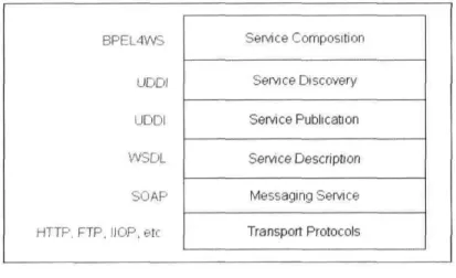
To achieve the interaction between the three rôles shown in figure , in an interop-erable manner, many organisms and consortiums including the principle software and hardware vendors define a Web Services stack built on well established standards, par-ticularly: Simple Object Access Protocol (SOAP), Web Services Description Language (WSDL), and Universal Description, Discovery, and Intégration (UDDI) [59]. As shown in Figure . , this stack consists mainly of the following layers: service protocol, mes-saging service, service description, service publication, service discovery. and service composition. BPEL4WS UDDi UDDI WSDL SOAP HTTP, FTP, IlOP.etc Service Composition Service Discovery Service Publication Service Description Messaging Service Transport Protocols
Figure 2.7: Web Services Stack
protocol to transfer information as a load over communication protocol. Because of its incontrovertible popularity and ubiquity, HTTP is the de facto standard transport protocol for Web Services. HTTP does not exclude the other Internet protocols, therefore many others can be supported, including FTP and SMTP. For Intranet (inside the organization), communications can use reliable messaging and call infrastructures [30] like Java Messaging Service (JMS), CORBA, etc. • Messaging Service: The next layer, XML-based messaging based on Simple
Ob-ject Access Protocol (SOAP), a standard defined by W3C. SOAP acts as the envelope for XML-based messages. SOAP provides standard mechanisms for en-veloping, communicating document-centric messages, and remote procédure calls using XML [30]. Moreover, SOAP messages support différent opérations to de-scribe, discover and use the services (publish, find and bind).
• Service Description and Publication: Service Description defines the interface of an implemented service. It signifies common business transactions (e.g. sending a purchase order), common data-interchange formats and mechanisms to negotiate business terms among organizations before commencing transactions. Since the service is defined in a an XML-standard. Any global consumer can automatically interpret a service and use it through defined interface to suffice his/her own interests. Web Service Description Language (WSDL) is the de-facto standard for service description. A WSDL document simply describes what the service can do, where it résides and how to invoke it through the binding with SOAP1.1, HTTP GET/POST, etc. Once the service provider describes the service, it is time to publish it in a service registry or repository. The most dominant standards for service publication are UDDI [59] and eXtensible Markup Language (ebXML) [89]
• Service Discovery: As stated before, Service Discovery is implemented in a mech-anism that lists organization's capabilities for business transactions and provides a look up facility to company profile. Service Discovery uses its own XML reposi-tory system (ebXML) or other reposireposi-tory (UDDI). Once agreed, service discovery System binds the producer and consumers. A standard based open spécification for Service Description and Discovery is achieved in Universal Description, Dis-covery and Intégration (UDDI). However, Java based implementation of UDDI uses JAXR (from Sun Microsystems) interface to unify and speed up transactions from différent repository Systems.
The aforementioned description of Web Services is stateless as implemented in WSDL. Therefore, it offers exécution of a whole process in response to customer's request. However, human requests are often too complicated to be served by a single
service. It requires composition of multiple services to accomplish the required work flow. As WSDL being stateless and unable to capture intermediate states; a language, on top of WSDL, that deals with work flow becomes a necessity. This necessity in-troduces another Web Service layer, called Service Execution. Software vendors implemented a number of process exécution languages. The most promising one may be considered is Business Process Execution Language for Web Services (BPEL4WS) provided by many industry leaders such as BEA Systems, IBM, Microsoft, SAP AG, Siebel Systems, etc.
2.7 Messaging Service
For information sharing purposes, any EAI solution requires a communication layer [71] between différent connected Systems called middleware. This layer enables transparent interaction between applications by masking the complexities related to each one.
2.7.1 Types of Middleware
A middleware cornes under various forms: Transactional Processing Monitors (TP), Remote Procédure Call (RPC), and Messaging Oriented Middleware (MOM).
First, Transactional Monitors technology [8, 17] emerged in the beginning of the 1980's to balance the proeessing load problems on the mainframes, by splitting com-plex applications into small pièces of code called transactions. This technology performs business logic and manages database transactions. It is used in data management, net-work access, security Systems and delivery order proeessing . Second, RPC-based mid-dlewares [80] allow access to remote servers by using spécial function calls embedded within the client side of the client/server application program. When a client program is compiled, a local stub for the client side and another stub for the server side are created. When the application requires a remote function and typically support syn-chronous calls between clients and servers, thèse stubs are invoked. Tightly coupled, remote procédure call (RPC) puts serious handicap in system-to-system proeessing due to distinguished frameworks. Moreover, architecturally, CORBA, Microsoft's DCOM. and Java RMI maintain many-to-many connection framework based on their own syn-chronous communication protocol. A caller is blocked until the procédure complètes remotely and returns control to the caller. Consequently a distributed middleware
fol-lows highly interdependent nature, where one failure on a system has immédiate and deliberating impact on other Systems. Finally, MOM, which we will présent in détail hereafter, represents a better alternative for TP and RPC-based middleware.
2.7.2 Messaging Oriented Middleware
A Messaging Oriented Middleware [C9] is a software that résides in both sides of a client/server architecture and typically supports asynchronous communications between the client and server tiers. Hereafter, we highlight this communication middleware, its architecture, messaging models, styles, and follow up by detailing the standard Java messaging service, one of the most widely accepted and used messaging services.
For an enterprise application, a message is a lightweight entity that consists of a header and a body. The header contains fields used for message routing and identifica-tion. However, the body contains the application data being sent.
A Message Oriented Middleware exchanges information in a message format, gen-erally created by an API, places it as a payload (application data) on the network protocols, and assigns the routing information. In addition, the messaging service de-couples the user application from data or service sources and therefore allows seamless intégration of resources inside and outside the organization with significant improve-ment in quality of service .
2.7.3 Classification of Messaging Service
Message Oriented Middlewares exist in several industrial products. IBM MQSeries (become IBM WebSphere MQ) [88], Microsoft MSMQ [49], TIBCO Rendezvous [85], Modulus InterAgent [57], etc. are examples of thèse products. Thèse MOM products can be classified according to their messaging architecture, model, and style.
Messaging Architecture
Each enterprise system follows an architecture which is centralized, decentralized or hybrid [69]. Implementing a messaging System for information exchange is not an exception.
• Centmlized architecture: Centralized messaging Systems rely on a single message server that routes the message and contains the request response broker that holds implementation détails of its messaging clients. Clients are added to the server and post messages to their server. Therefore, any client can be added or deleted without impacting the whole system. A centralized server may be a distributed cluster working as a single logical unit.
• Decentralized architecture: Decentralized architecture does not rely on a single server. Each client is given some server-like facilities (persistence, transactions, security) and the router implements IP multi-casting functionalities to allow a message requests to other messaging clients.
• Hybrid architecture: Messaging vendors generally implement both of the above-mentioned architectures. Centralized multicast is generally implemented on TCP/IP communication protocol, while the decentralized counterpart is on IP multicasting protocol.
Existing messaging products follow the aforementioned architectures as per their requirements. Messaging service of SonicMQ [79] allows centrally managed messag-ing components. TIBCO Rendezvous utilizes a distributed architecture to eliminate bottlenecks and single points of failure. MSMQ [87], a part of the Microsoft DNA ar-chitecture, has two components: MQ site controller (SC), that store read-only copies of messages in a queue, located in client-side end; and a primary enterprise controller (PEC) that résides in the central MQ server side, that keeps the broker and stores the queue détails.
Messaging Model
A MOM follows one of two modes: Point-to-Point (P2P) model and Publish-and-Subscribe (Publish/Publish-and-Subscribe) model [79].
Point-to-Point model: P2P messaging model uses a connection component that
allows one-to-one delivery of messages. More precisely, a message producer cré-âtes a message and put it in a 'queue' inside the 'messaging domain'. Afterwards, a consumer can receive that message from the same queue. Point-to-point mes-saging confirms loose coupling between single producer and single consumer at a time.
Publish-and-Subscnbe model: Publish-and-subscribe is a one-to-many
broadcast-ing model of messagbroadcast-ing. Message based middleware Systems use this technique to allow an application sending the same request to multiple other applications. Each consumer receives a copy of the same message in nearly same time. The virtual repository channel of the messaging domain is called 'topic'.
Messaging model defines handling of messages sent to or from a particular site. Auction sites, stock quote service, or security services often require to push data to huge population of consumers. Différent vendors approach différent styles. For example, MSMQ from Microsoft supports queue based one to one messaging, while the présent versions of SonicMQ and TIBCO Rendezvous work with both aforementioned models.
Messaging Style
An important feature of messaging service is its ability to découplé two applications to share information or processes. The basic infrastructure of RPC [76] is strictly synchronous . However, messaging [69] allows both synchronous and asynchronous communication as required in the enterprise Systems.
Synchronous messaging; Synchronous messaging tightly couples messaging
com-ponent (called destination) and receiver of messages. It provides an advantage for fail-safe communication and transaction processing. However, the receiver is bound to destination until it finishes the processing of the sender's request. Net-work and both communicating processes must be available during the communi-cation. A synchronous consumer [14] uses a pull technique to receive messages from a destination .
Asynchronous messaging: Asynchronous Messaging style uses 'store and forward'
mechanism. Design of this messaging allows one/many connection component(s) between the sender and receiver. An asynchronous consumer registers a message listener to a destination. Thèse components allow the sender and receiver non-blocking to each other. When a message arrives, the implemented listener model informs the consumer with a message. Consequently, the client frees the messaging structure and failure of a client does not affect the whole System.
Most of the business solutions introduce the asynchronous paradigm in their mes-saging solution. However, certain situations require synchronous solutions, while the
information is required to be compromised only between the sender and receiver for transaction processing, for instance. TIBCO Rendezvous provides support for re-quest/reply, publish/subscribe, and synchronous/asynchronous mesaging. Similarly. IBM Websphere MQ séries, Sonic messaging products implements both notions in their messaging styles with limited variations.
2.7.4 Java Message Service
According to our objective, the proposed middleware System requires both; peer-to-peer communication and broadcasting of messages for enterprise-wise intégration of infor-mation Systems. After an intensive research on différent technologies and assessing the available messaging products, Java Message Service (JMS) has been chosen as the most prominent technology in our design and implementation. JMS is the Java messaging standard, released in 1999 [51, 52] and used by most of the leading industries includ-ing, Sun Microsystems, Sonic MQ, IBM Websphere, BEA Weblogic, etc. It leverages a union of ail the existing features of messaging service and includes functionalities of sophisticated enterprise applications in portable messaging applications. The main objectives behind JMS are the following:
• Provide a single unified message model that can be implemented as an API (JSR 914).
• Allow cross vendor communication in the messaging service level with applications that do not use JMS but support similar spécifications.
• Integrate multiple heterogeneous sources of information and services, with XML support, through communication of Java objects.
• Implement another layer between application and communication layers and thereby enforcing magnitude of enterprise properties like security, portability, reliability etc.
• Implement a new notion of asynchronism, much needed for intégration of both intra and/or inter organizations.
• Extend support to numerous Java based APIs: Java DataBase Connectivity (JDBC), Java Transaction API (JTA), and Enterprise Java Beans (EJB) com-ponents.
JMS API Architecture
A JMS application is composed of the following parts [33]: a JMS Provider, Clients, Messages, and Administered objects.
• Provider: Each JMS application runs on a host application, called JMS provider. A JMS provider implements the JMS interfaces and is responsible for administra-tive functions and control capabilities. Inside Java virtual machine, a distributed component résides within a 'provider' application. This container hosts 'bro-ker' and other JMS components that hold the messaging implementation détails [41, 79].
• Clients: Clients are JMS applications that use the provider components to pro-duce and consume messages. A client can be synchronous or asynchronous to the JMS destinations to send or receive messages. JMS is implemented in a way to support JMS and non JMS clients through Java application or other client APIs [G9].
• Messages: A JMS message carries application data and event notifications in flexible and dynamic way. Unlike RPC, messages neither dictate the récipient nor block the sender. A Message object consists of a message header and the message itself, called payload. Most of the message headers are automatically assigned and détermine JMSDestination, JMSDeliveryMode, JMSMessagelD, JMSTimestamp, JMSPriority, etc. A Message object contains a built-in facility for supporting application-defined property values. Actually, this provides a mechanism to add application-specific header fields to a message. Properties allow an application, via 'message selectors', having a JMS provider sélect, or filter, messages on its behalf using application-specific criteria. A message selector mechanism is used by the consumer to filter out its spécifie messages. JMS message payload has the base interface defined in javax.jms.Message. Payload might be structured like StreamMessage or fairly unstructured as in TextMessage [51].
• Administered objects: Administered objects are pre-configured JMS Objects cre-ated by an administrator to control the message-based communication. The ad-ministrator binds thèse objects inside the Java Naming and Directory Interface ( JNDI) namespace prior to the messaging. Administered objects are of two types: ConnectionFactory and Destination. Once, created they provide abstraction to the namespace by hiding implementation complexities through this virtual and dynamic interface. Therefore, a client program exécutes with minimal program-ming required to 'lookup' a spécifie object. Administered objects always
impie-ment standard based profile, and therefore remain portable despite proprietary aspects of JMS providers [24, C9j.
Apart from the aforementioned components, JMS uses a directory service for the storage of implementation spécifie settings of distributed JNDI components. Directory service is a file system that allows clients to look up a named connection factories or destinations defined by administrators. Generally, it uses Lightweight Directory Access Protocol (LDAP) [21] server to store the administered objects.
JMS Model
The basic building blocks of a JMS application consist are: Administered objects, Connections, Sessions, Message producers, Message consumers, and Messages (Figure
In gênerai, a directory service has its own domain managed by a domain man-ager. The domain manager [79] controls administered objects within multiple vir-tual containers and allows communication between them. JMS messaging requires proper configuration of administered objects in JNDI prior to messaging. First, ad-ministered objects are required to be bound to JNDI using administrative tools. Once Corme et ionFactory and Destination are created in the JMS server and ail of its implementation spécifie information are kept within the system, and JMS is ready to start communication. A developer should create a Connection initially from a valid and bound JMS ConnectionFactory. As it allows multi-threading, a Connection-Factory may handle multiple connections simultaneously. JMS messaging is session based. A Session object implements a particular valid Connection. A Connection is capable also to handle multiple sessions at a time. However, there are strict re-strictions imposed on concurrent access into Sessions. The objective of a session is to implement transactions in synchronous or asynchronous messaging. Therefore, JMS spécification reserves the access to a session by a single message consumer. How-ever, sophisticated design may allow multi-session related to a single connection to process concurrent requests from users. Each application process runs under a particu-lar session. JMS user applications are of two types: QueueSender/QueueReceiver and TopicPublisher/TopicSubscriber. QueueSender/QueueReceiver application sends and receives messages to/from a Queue, while TopicPublisher/TopicSubscriber pub-lishes and subscribes information to/from a Topic. JMS send/receive (in JMS Queue) and publish/subscribe (in JMS Topic) [51, 09] are detailed in the next subsection . The pièce of code illustrâtes a simple JMS sender application as described above.
import javax.jms.*; import javax.naming.* ;
public class JmsQueue {
Context jndiContext=null;
QueueConnectionFactory qCF = null; QueueConnection qC = null;
QueueSession qSess = null;
Queue queue= null; QueueSender qS = null; TextMessage message=null;
public qSendO {
//Initial lookup to Administered Objects assuming they are already created.
t r y {
jndiContext = new InitialContextO ;
qCF = (QueueConnectionFactory)jndiContext.lookup(QueueConnectionFactory); queue = (Queue) jndiContext.lookup(TestQ);
} catch(NamingException e) {}
//Création of connection, session and message sender. t r y {
qC = qCF.createQueueConnectionO ;
qSess = qC.createQueueSession(faise,Session.AUTO ACKNOWLEDGE); qS = qSess.createSender(queue);
} catch (JMSException e ) O
/ / Création of message and sending i t to the queue, t r y {
message = queueSession.createTextMessageO; qS.send(message);
} catch (JMSException e) {} }
JMS messaging implements one-to-one and one-to-many messaging models in the same API. As mentioned earlier, JMS destination objects are of two types: Queue and Topic. A queue allows exchange of message objects through a virtual channel, that fol-lows First In First Out(FÏFO) model. Despite existence of multiple receivers waiting, a queue ensures the retrieval of message by a single queue's receiver at a time. A consumer
Client Application ^Connection Factory) créâtes Connection créâtes Session Message Producer créâtes
1
Message > 1 binds T publishes "5.U ort
subscribes sends•J»C Queue > • Client Application C Connection Factory ,> ^ créâtes | Connection ~ | ^ créâtes Session IMessage SubscribarMessage
extract
Client Application
g iver
Figure 2.8: JMS Messaging Model
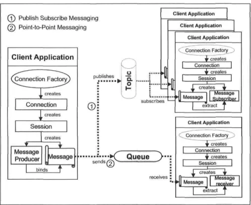
receives the messages in the same order as they are placed in the queue inside message server. JMS point-to-point messaging paradigm uses a storage inside each server node that keeps the messages for certain duration as configurée!. Queues are also used for load-balancing as well when many diverse Systems share processing opérations through a proper distribution of incoming messages. The JMS publish-subscribe messaging is implemented through a connection component, called JMS Topic. A topic implements a multi-threaded architecture that is capable of publishing a message object to its sub-scribers. A JMS publisher application places a single message into the message server and the later multicasts copies of the same object and distributes to ail subscribers simultaneously. Figure represents both of the JMS messaging models. However, subscribers may be synchronous, asynchronous or durable. A durable subscription ac-cepts message for a subscriber even while the application is not connected. JMS also allows to configure various properties to improve the performance and reliability of the System.
The most important aspect of JMS messaging System lies in the loose-coupling be-tween message producer and message consumer. Messaging service outweighs temporal dependency on the command based tightly-coupled process communication mechanism as in Remote Procédure Calls. According to JMS spécification, the producer releases a message to the connection component irrespective of the availability and processing
interval of receiving application. On the other hand, the consumer receives the mes-sage from the respective JMS component of the server in its side. Using Java mesmes-sage driven beans, a producer often créâtes temporary topic with JMSReplyTo header to put messages asynchronously in the destination. Messages are communicated through "store and forward" mechanism. In the following, we describe various binding technique related to the retrieval of messages from a JMS destination component [24, 09].
• Synchronous consumer: A synchronous subscriber, waits for a message always or for a specified duration (if the program implements onTimeOutOmethod to deac-tivate the listener). As it receives the message, the listener sends it for process-ing and then blocks to receive again. JMS listener' provides an onMessageQ method. In the programming level, the functions QueueReceiver.receive() and TopicSubscriber. r e c e i v e ( ) for synchronous retrieval of message [09].
• A synchronous consumer: An asynchronous consumer receives the message when a message arrives but does not block the connection between the destination and application process. An asynchronous JMS message listener is programmed with event based notification inside onMessageO method. Implementation is done using receiveNoWaitO method. However, as it receives the message, it may or may not use message selector to filter the incoming messages from more than one topic. Loosely coupled asynchronous consumer is more useful for free information exchange, except thcre is a typical need for synchronous transaction.
• Durable consumer/subscriber: Durable subscription frees the consumer from stay-ing continuously connected to the JMS server. "Store and forward" messagstay-ing mechanism also allows server to store messages inside server on behalf of a sub-scriber while client program is not available. It allows guaranteed messaging so that the consumer receives ail the messages at re-connection, irrespective of the duration of staying disconnected [09]. A JMS durable-subscriber may be defined through createDurableSubscriberQ method within a session.
2.7.5 JMS Properties
According to its spécification, JMS inherits a large number of features with enough scope of further development. The properties of JMS API may be classified into two catégories: architectural properties and message properties.