Science Arts & Métiers (SAM)
is an open access repository that collects the work of Arts et Métiers Institute of Technology researchers and makes it freely available over the web where possible.
This is an author-deposited version published in: https://sam.ensam.eu Handle ID: .http://hdl.handle.net/10985/9262
To cite this version :
Patrick DUPONT, Annie-Claude BAYEUL-LAINE, Antoine DAZIN, Gérard BOIS, Olivier
ROUSSETTE, Qiaorui SI - Leakage flow simulation in a specific pump model - IOP Conf. Series: Earth and Environmental Science - Vol. 22, p.1-10 - 2014
Any correspondence concerning this service should be sent to the repository Administrator : [email protected]
Leakage flow simulation in a specific pump model
P. Dupont1, A.C. Bayeul-Lainé2, A. Dazin2, G. Bois2, O. Roussette2, Q. Si3
1LML, UMR CNRS 8107, Ecole Centrale de Lille, Cité Scientifique - CS20048, 59651 Villeneuve d'Ascq Cedex, France
2LML, UMR, CNRS 8107, Arts et Métiers PARISTECH, 8, boulevard Louis XIV 59046 Lille Cedex, France
3
ResearchCenter of Fluid Machinery Engineering and Technology, JiangsuUniversity, Zhenjiang, Jiangsu 212013, China
Abstract. This paper deals with the influence of leakage flow existing in SHF pump model on
the analysis of internal flow behaviour inside the vane diffuser of the pump model performance using both experiments and calculations. PIV measurements have been performed at different hub to shroud planes inside one diffuser channel passage for a given speed of rotation and various flow rates. For each operating condition, the PIV measurements have been trigged with different angular impeller positions. The performances and the static pressure rise of the diffuser were also measured using a three-hole probe. The numerical simulations were carried out with Star CCM+ 8.06 code (RANS frozen and unsteady calculations). Comparisons between numerical and experimental results are presented and discussed for three flow rates. The performances of the diffuser obtained by numerical simulation results are compared to the performances obtained by three-hole probe indications. The comparisons show few influence of fluid leakage on global performances but a real improvement concerning the efficiency of the impeller, the pump and the velocity distributions. These results show that leakage is an important parameter that has to be taken into account in order to make improved comparisons between numerical approaches and experiments in such a specific model set up.
1. Introduction
This work is an extended study that had originated in LML laboratory concerning the well-known SHF (Société Hydrotechnique de France) pump. A lot of experimental data have already been produced (tests in air and in water) on that geometry and these results are used as databases for the validation of numerical calculation results and for new experimental results [1-8]
Flow behaviour in a radial machine is quite complex and strongly depends on rotor stator interactions and operating conditions [9-11].
In numerical simulations, two aspects have to be considered:
- The first one concerns the governing equations which are solved in the model. Three kinds of numerical calculations are currently used in turbo machinery (frozen rotor calculations, mixing plane calculations, unsteady calculation). The frozen rotor calculation is the steady state method which uses the rotating reference frame to save the computational resources by converting inherently transient turbo-machinery flow into steady state. The difference between a frozen rotor and a mixing plane calculation is that the mixing plane mixes the flow and applies the average quantities on the interface
for upstream and downstream components, while a frozen rotor will pass the true flow to downstream and vice versa. So if the wake effect on the downstream component performance is necessary, the frozen rotor method has to be used. A big disadvantage is that it gives the solution at a single relative position. The true transient method gives the wake effect on the downstream component for all relative positions (as it happens in reality) [12-14].
- The second aspect concerns the geometrical model. Some geometrical simplifications are currently used. For example, the leakage flows are often neglected. It is obvious that a complex model (fully unsteady, with leakage flows) will be more time consuming but closer to the real physics. In the presence of a gap, a leakage flow appears due to the difference of static pressure at the clearance between the shroud and the outer casing and between the hub and the outer casing.
In this respect, the effects of fluid leakage due to the gap between the rotating and the fixed part of this pump model are analysed and discussed.
In this paper, some limits of the numerical models are pointed out. To do so, several numerical calculations have been carried out: i-Frozen rotor without leakage, ii-Unsteady RANS calculations without leakage, iii-Frozen rotor with leakage and iv-Unsteady RANS calculations with leakage
These numerical results are compared to experimental results for three flow rates to try to evaluate the effects of the numerical models on the prediction of the performance and on the local behaviour of the flow.
2. Experiments
2.1. Test and apparatus
Figure 1. Apparatus: PIV measurement, laser sheet. Figure 2. Apparatus: three-hole probe. The test model corresponds to the so-called SHF pump, working with air, in similarity conditions compared to water, for which several studies have been made [1-5;15-16] involving numerical and PIV comparisons. The Optical assembly to create a laser sheet in one diffuser blade passage can be shown in figure 1.The existing database has been completed by pressure probe measurements for a complete performance analysis in the vane diffuser part of the pump model. The test rig used for the
Inlet pressure measurement
Shroud Hub Three-hole probe Impeller Diffuser Laser sheet Probe station Diffuser
three-hole probe (figure 2) was the same as the one already developed for the PIV measurement already described in the previous papers, especially in reference [4].
Impeller Diffuser
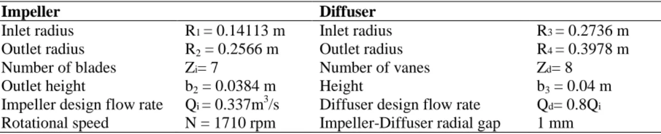
Inlet radius R1 = 0.14113 m Inlet radius R3 = 0.2736 m Outlet radius R2 = 0.2566 m Outlet radius R4 = 0.3978 m Number of blades Zi= 7 Number of vanes Zd= 8
Outlet height b2 = 0.0384 m Height b3 = 0.04 m
Impeller design flow rate Qi = 0.337m3/s Diffuser design flow rate Qd= 0.8Qi Rotational speed N = 1710 rpm Impeller-Diffuser radial gap 1 mm
Table 1. Pump characteristics.
Test pump model and PIV measurements conditions have been already described in several papers [3-4] and main pump characteristics are given in table 1.
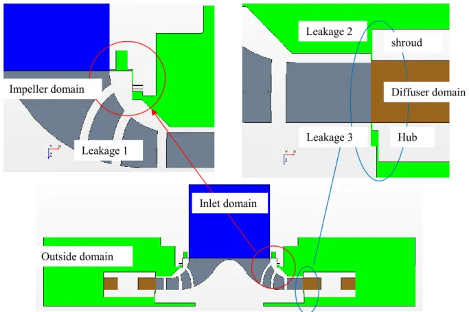
Two sources of fluid leakage occur:
- The first one at the impeller inlet (leakage 1, figure 6)
- The second one between the impeller outlet and the diffuser both for the hub and the shroud sides (leakages 2 and 3, figure 6).
2.2. PIV measurements
PIV measurements have been performed at different hub to shroud planes inside one diffuser channel passage for a given speed of rotation and various flow rates. For each operating condition, the PIV measurements have been trigged with different angular impeller positions (figure 3). For each angular position, several instantaneous velocities charts have been obtained, covering the space between inlet and outlet diffuser throats. This makes a rather good evaluation of phase averaged velocity charts possible. The PIV results are extracted from the thesis of G. Cavazzini, [2].
2.3. Three holes probes
A directional three holes probe has been used to make hub to shroud traverses [17]. Using a specific calibration one can get total pressure, static pressure, absolute velocity and its two components in radial and tangential direction.
In order to well represent the flow field, twenty-three probe locations are defined as it can be seen in figure 5. For each location, ten axial positions are registered (b*=0.125, 0.2, 0.25, 0.375, 0.5, 0.625, 0.75, 0.875, 0.925, 0.975 from hub to shroud). The present analysis focuses only on locations 19 to 23 along the blade to blade diffuser channel.
Figure 3. Impeller different angular positions relative to the diffuser vanes.
Figure 4. Probes for frozen
rotor calculations. Figure 5. Diffuser measurement locations for probe traverse and unsteady calculations.
3. Calculations
Calculations were carried out with Star CCM+ 8.06 code. The sketches of the gaps are really taken account (figure 6). A complete meshing was set up with the real geometry of the gaps and external domain far upstream the labyrinth. In this respect, boundary conditions include the relative casing motion of the model.
The calculation domain is divided into four domains: - Inlet domain,
- Impeller domain, - Diffuser domain,
- Exterior domain as can be seen in Figure 6.
As thickness gaps are very small (1 mm), a thin meshing model has been chosen. A thin meshing model allows thin regions in the geometry to have a prismatic type volume mesh. Using this kind of mesh improves the overall cell quality and reduces the cell amount when compared to an equivalent polyhedral type core mesh. The number of layers in the thin mesh has been set to 10. In the other parts of the domain, a polyhedral mesh with prism layers is used for all calculations (5 prism layers for a total prism layer thickness of 1 mm). The target size is 3 mm and the minimum size 0,5 mm . The size of the grid is about 18. 106 cells for all the four domains.
Figure 6. Regions modelled. Details of fluid leakages.
Three-dimensional incompressible Reynolds averaged Navier–Stokes equations are solved in steady (frozen rotor) and unsteady states. The SST k turbulence model is used [7, 18].
The boundary condition at the inlet consisted of a mass flow rate (Q*=0.766; 0.973; 1.134). The boundary condition at the outlet was the atmospheric pressure (relative pressure=0 Pa). The boundaries of the outer casing of the impeller are considered as rotating walls. The fluid (air) was considered incompressible at a constant temperature of 20ºC.
Leakage 1
Leakage 2
Outside domain
Inlet domain
Impeller domain Diffuser domain
Hub shroud
For frozen rotor calculations, line probes are plotted in the whole domain of the diffuser (figure 4): each probe is duplicated seven times in order to obtain all parameters (pressure, total pressure, radial, tangential and axial velocity and velocity magnitude) for different relative positions of the diffuser comparatively to the impeller (figure 3). This is equivalent to azimuthal positions equal to n* 360/(Zi*Zd) with n=0,1 ,2, 3, 4, 5, 6 and 7.
For unsteady calculations, point probes are plotted in the blade to blade channel of the diffuser as can be seen in figure 4.
The convergence criteria are less than 1.e-4. The values of y+ are below 15 in the whole computational domain.
4. Results and analysis
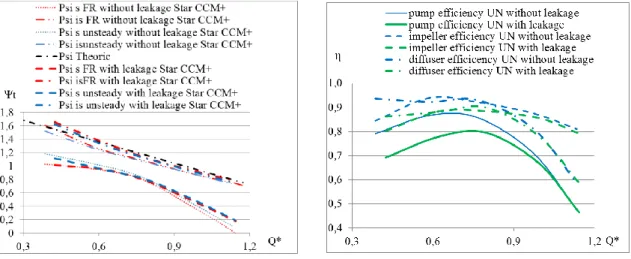
Let us first examine the global results: the non-dimensional static pump head, the non-dimensional isentropic pump head, the impeller efficiency, the diffuser efficiency and the pump efficiency.
These calculations show few influence of fluid leakage on global performances (figure 7). Global results of static theoretical head pump are in good agreement between one dimensional approximation using EULER equation with no inlet flow swirl and frozen rotor calculation. Unsteady calculation results, performed for the three non-dimensional flow rates, give the same level, as it can be seen in figure 7. The numerical non-dimensional isentropic pump head is higher when the fluid leakages are modelled in case of frozen rotor and in case of unsteady calculations. This leads to a decrease of impeller efficiency and pump efficiency due to fluid leakages (figure 8). It can also be noticed that the pump efficiency falls at high flow rate. The diffuser efficiency is higher at low flow rate and decrease with flow rate with and without fluid leakages for frozen rotor calculations. This is due to the fact that the diffuser is not well adapted at high flow rate. It is well adapted at Q*=0.766 as can be observed in figure 8
Figure 7. Performances: static and isentropic . Figure 8. Impeller and pump efficiency
Figure 9. Fluid leakages at impeller inlet
Figure 10. Fluid leakages at impeller/diffuser hub
Figure 11. Fluid leakages at impeller/diffuser shroud
Fluid leakages are calculated for the three different locations: inlet (leakage 1), hub side (leakage 2) and shroud side (leakage 3) with frozen rotor and unsteady calculations. The impeller rotation effect was taken into account in the numerical solution.
Wuibaut [2] and Cherdieu [17] calculated analytical solutions, based on friction losses and localized minor losses of charge, for each leakage. The impeller rotation effect was not taken into account in this analytical solution. By writing the Bernoulli’s theorem, each leakage flow rate has been calculated knowing the total difference pressure between the inlet and the outlet of the gap.
Considering the leakage at the impeller inlet, only localized losses of charge in the labyrinth are taken account [2]. For the gap between the impeller and the diffuser on the shroud side, the losses are due to the contraction and the expansion through the gap for the localized part and also due to friction on the length of the ring [17]. For the gap between the impeller and the diffuser on the hub side, Cherdieu considered that the losses are the sum of two elbows, the contraction and the expansion [17].
b* = 0.12 5 b* = 0.50 0 b* = 0.87 5
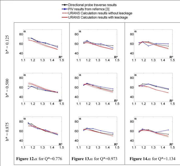
Figure 12. for Q*=0.776 Figure 13. for Q*=0.973 Figure 14. for Q*=1.134 The evolution of absolute velocity angle relative to radial direction inside the diffuser
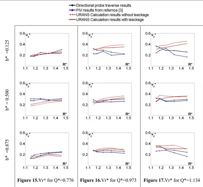
b* = 0.12 5 b* = 0.50 0 b* = 0.87 5
Figure 15.Vr* for Q*=0.776 Figure 16.Vr* for Q*=0.973 Figure 17.Vr* for Q*=1.134 The evolution of non-dimensional radial velocity Vr*inside the diffuser
All results are presented in Figures 9 to 11, fluid leakage are considered positive if they income inside the domain.
As can be observed, at the inlet gap, all methods lead to quite same results. In case of Star CCM+, fluid leakages are smaller at high flow rate.
Concerning, leakages at hub and shroud sides, the amount of flow rate depends on the flow rate in the pump. At low values of Q*, a positive leakage between impeller and diffuser was observed. At high values the tendency inverses as shown in figures 10 and 11.These tendencies were also observed in previous studies [7].
Considering fluid leakages flow rates, the analytical results seem to be sufficient enough to predict these flow rates as also shown by Khelladi et al [19]. So new calculations, without external domain but with fluid leakages flow rates based on analytical model, can be used to compare local numerical results and experimental results.
Local absolute velocity angle relative to radial direction and non-dimensional radial velocity are plotted in figures 12 to 17 for the three flow rates.
The examination of the evolution of the absolute velocity angle relative to radial direction for the two numerical calculations, for the PIV measurements and for the three holes measurements show similar results (figures 12 to 14). There is no real influence of taken account the fluid leakages on the evolution of the angles.
The examination of radial velocity (figures 15 to 17) shows that fluid leakages have a real influence for Q*=0.776 and Q*=0.973. For Q*=1.173, numerical results with fluid leakages are better than those without leakage, but some differences still remain with experimental results in particular flow at low values of b*.
5. Conclusion
In this paper, the SHF pump was studied numerically and experimentally. The computational models with and without gaps (between the impeller, the fixed inlet domain and the fixed diffuser domain) were set up for frozen rotor and unsteady solutions in order to determine the fluid leakages and to make comparisons with experimental results. A one dimensional loss model was also used to calculate the fluid leakages flow rates. The effects of the gaps on the calculated flow field were analysed. Local velocity components evolutions in the diffuser blade to blade channel have been calculated and analysed taking the leakage effects into account.
It has been found that the amount of fluid leakages corresponds to the one dimensional model, even if the effect of rotating wall wasn’t considered in this model. This result is very interesting knowing that the model with gaps is more consuming in grid size and in computational time than the case without gaps.
It has been shown that leakages may affect the local flow characteristics depending on volume flow rates at the impeller inlet. The calculations show little influence of fluid leakage on the global performance but present a real improvement concerning velocity distributions. The local fields of velocities were analysed inside the blade to blade channel using the numerical results, the PIV measurements and the three holes probes. These results show that leakage is an important parameter that has to be taken into account in order to make improved comparisons between numerical approaches and experiments.
The comparison of pump performances between the calculations and the measurements showed a favourable tendency.
Nomenclature
b [m] Distance from hub
b* b/B [-] Non-dimensional distance from hub
B [m] Blade height
C [mN] Impeller torque
dps Ps-ps1 [Pa] Static difference pressure
dpt pt-pt1 [Pa] Total difference pressure
dpti pt2’-pt1 [Pa] Impeller total difference pressure
dptp pt4-pt1 [Pa] Pump total difference pressure
N [rpm] Rotational speed
ps [Pa] Static pressure
pt [Pa] Total pressure
Q* Q/Qi [m3/s] Non-dimensional volume flow rate at impeller’s inlet
Qd [m3/s] Diffuser design flow rate
Qi [m3/s] Impeller design flow rate
Ql* Ql/Qi [-] non-dimensional flow rates of fluid leakage
R [m] Radius
Vr [m/s] Radial velocity
Vr* Vr/U2 [-] Non-dimensional radial velocity
Vu [m/s] Tangential velocity
Vu* Vu/U2 [-] Non-dimensional tangential velocity
U2 R2 [m/s] Frame velocity at blade’s impeller outlet
Zd [-] Number of diffuser blades
Zi [-] Number of impeller blades
p tp/i [-] Pump efficiency
i ti/i [-] Impeller efficiency
d p/i [-] Diffuser efficiency
Arctg(Vr/Vu) [°] Absolute velocity angle relative to radial direction
relative to radial direction
[kg/m3] Air density
πN/30 [rad/s] Angular Velocity
i CQU22/2) [-] Non-dimensional isentropic head
s dps/(U22/2) [-] Non-dimensional static pump head
tp dpti/(U22/2) [-] Non-dimensional total impeller head
ti dptp/(U22/2) [-] Non-dimensional total pump head
Index d Diffuser i Impeller p Pump 0 Domain inlet 1 Impeller inlet
2 Blade’s Impeller outlet
2’ Impeller outlet
3 Blade’s diffuser inlet
4 Blade’s diffuser outlet
References
[1] Wuibaut G., Dupont P., Caignaert G., Stanislas M. 2000Experimental analysis of velocities in the outlet part of a radial flow pump impeller and the vanelessdiffuser using particle image velocimetryProceedings of the XX IAHR Symposium(Charlotte USA) 6-9 august, paper GU-03. [2] Wuibaut G. 2001 Etude par vélocimétrie par images de particules des interactions
roue-diffuseurdansunepompe centrifuge PhD thesis, Thèse de DoctoratEnsam
[3] Cavazzini G. 2006 Experimental and numerical investigation of the rotor-stator interaction in radial turbomachines, Ph.D. thesis, University of Padova, (Padova, Italy)
[4] Cavazzini G., Pavesi G., Ardizzon G., Dupont P., Coudert S., Caignaert G., Bois G. 2009 Analysis of the rotor-stator interaction in a radial flow pump Houille blanche –Revue internationale de l’eau p. 141-151
[5] Cavazzini G., Dupont P., Pavesi G., Dazin A., G.Bois, Atif A., Cherdieu P. 2011 Analysis of unsteady flow velocity fields inside the impeller of a radial flow pump : PIV measurements and numerical calculation comparisons Proc. of ASME-JSME-HSME Joint fluids engineering conferenceJuly 24-29,(Hamamatsu, Japan)
[6] Cherdieu P., Dupont P., Bayeul-lainé A.C., Dazin A., Bois G., 2013 Data reduction problems using a 3 - hole directional pressure probe to investigate mean flow characteristics in the vaneless gap between impeller and diffuser radial pump, IOP Conference Series Earth and Environmental Science09/2013; 52(topic 2).
[7] Bayeul-Lainé A.C., Dupont P., Cavazzini G., Cherdieu P., Dazin A., Bois G., Roussette O.,. 2013 Numerical and experimental investigations in a vaneddiffuser of SHF impeller : fluid leakage effect 21 èmeCongrèsFrançais de Mécanique(Bordeaux) 26-30 août
[8] Bayeul-Lainé A.C., Dupont P. , Miccoli L., Cavazzini G., Dazin A., Pavesi G., Bois G.2014 Fluid leakage effect on analysis of a vaneddiffuser of SHF pump, 15th International Symposium on Transport Phenomena and Dynamics of Rotating Machinery, ISROMAC-15, (Honolulu, Hawai, USA); 02/2014
[9] Adamczyk J. J., Celestina M. L., Chen J. P. 1994 Wake induced unsteady flows :their impact on rotor performance and wake rectification ASME International Gas Turbine and Aeroengine Congress and Exposition(The Hague, Netherlands), June 13-16, paper 94GT219.
[10] Arndt N., Acosta A.J., Brennen C.E., Caughey T.K 1990 - Experimental Investigation of Rotor – Stator Interaction in a Centrifugal Pump With Several VanedDiffusers ASME Journal of TurbomachineryVol. 112 p. 98-108.
[11] Eisele K., Zhang Z., Casey M. V., Gülich J., Schachenmann A. 1997 Flow analysis in a Pump Diffuser Part 1 : LDA and PTV Measurements of the Unsteady FlowTransactions of ASME, Journal of Fluids EngineeringVol. 119 p. 968-977
[12] Culver R., Liu F. 2009 Plane Method for Flutter Computation in Multi-stage Turbomachines47th AIAA Aerospace Sciences Meeting Including The New Horizons Forum and Aerospace Exposition January5-8, (Orlando, Florida)
[13] Petit O., Nilsson H. 2013 Numerical Investigations of Unsteady Flow in a Centrifugal Pump with a vanedDiffuserInternational Journal of Rotating Machinery, Vol. 2013, Article ID 961580, 14 pages
[14] Tamm A., Gugau M., Stoffel B.2002 Experimental and 3-D Numerical Analysis of the Flow Field in Turbomachines- Part I International Congress on Quality Assesment of Numerical Simulations in Engineering(Conception – Chile)
[15] Dazin A., CoutierDelgosha O., Dupont P., Coudert S., Caignaert G., Bois G., 2008 Rotating Instability in the VanelessDiffuser of a Radial Flow Pump Journal of Thermal Science17 (4) 368-374
[16] Dazin A., Cavazzini G., Pavesi G., Dupont P., Coudert S., Ardizzon G., Caignaert G., Bois G. 2011 High-speed stereoscopic PIV study of rotating instabilities in a radial vanelessdiffuserExp Fluids51(1) 83-93
[17] Cherdieu P. 2014 Contrôle du décollementdans un diffuseuraubé de turbomachine centrifuge PhD thesis, Thèse de Doctorat
[18] Menter, F. R. and Kuntz, M. 2002. Adaptation of Eddy Viscosity Turbulence Models to Unsteady Separated Flows Behind Vehiclesin The Aerodynamics of Heavy Vehicles: Trucks, Buses and Trains Springer Asilomar CA.
[19] Khelladi S., Sarraf C, Bakir F., Rey R. 2010 Study of a high rotational speed shrouded centrifugal, fan: aerodynamics and effects of a shroud-associatedProceedings of the Institution of Mechanical Engineers Part A Journal of Power and Energy, 01/2010; 224(5):691-700. DOI:10.1243/09576509JPE899