Science Arts & Métiers (SAM)
is an open access repository that collects the work of Arts et Métiers Institute of
Technology researchers and makes it freely available over the web where possible.
This is an author-deposited version published in: https://sam.ensam.eu Handle ID: .http://hdl.handle.net/10985/7494
To cite this version :
Sébastien CAMPOCASSO, Jean-Philippe COSTES, Guillaume FROMENTIN, Stéphanie BISSEY BRETON, Gérard POULACHON - Improvement of Cutting Forces Modeling Based on Oriented Cutting Tests - In: 14th CIRP Conference on Modeling of Machining Operations, Italy, 2013-06-13 - Procedia CIRP - 2013
Any correspondence concerning this service should be sent to the repository Administrator : archiveouverte@ensam.eu
Improvement of cutting forces modeling
based on oriented cutting tests
Sébastien Campocasso
a,*, Jean-Philippe Costes
a, Guillaume Fromentin
a,
Stéphanie Bissey-Breton
b, Gérard Poulachon
aaArts et Metiers ParisTech, LaBoMaP, 71250 Cluny, France bCEA, DAM, Valduc, 21120 Is-sur-Tille, France
* Corresponding author. Tel.: +33-385-595-388; fax: +33-385-595-370. E-mail address: sebastien.campocasso@ensam.eu.
Abstract
In order to predict the characteristics of the machined part, such as geometry, surface roughness and fatigue or corrosion resistance, the cutting forces values should be known as precisely as possible.
The edge discretisation methodology can be used to model the three components of the cutting forces. The results are generally considered as suitable, even if the considered cutting operation is complex, because the geometry is well described.
Usually, the local cutting forces model is identified from orthogonal or oblique cutting tests and the local contributions are assumed to be independent of the orientation of the elementary edge in the reference plane P . r
However, when turning in the tool nose or with round inserts, the tool cutting edge angle r (or Side Cutting Edge Angle) evolves
along the active cutting edge and the values of this angle are very small compared to that of 90° used in orthogonal/oblique cutting. For this study, a new elementary cutting operation, called “oriented cutting”, has been tested. In this configuration, the active cutting edge is rectilinear, without inclination, but oriented by an angle r different from 90°. In addition, cylindrical turning tests
have been done.
The measurements, performed in pure copper, show an influence of the tool cutting edge angle on the cutting forces. An interaction between r and the workpiece radius is also highlighted.
Keywords: Cutting forces modeling; Edge discretisation; Oriented cutting tests; Pure copper
1. Introduction
The calculation of cutting forces is of interest to predict the characteristics of the machined part as geometry, surface roughness or material integrity.
One possible way to model the forces is to use the edge discretisation as presented on Figure 1.
This methodology allows considering the local uncut chip thickness [1], which is particularly interesting in finish turning (apr).
Indeed, when cylindrical turning in the nose or with round insert, the uncut chip thickness evolves along the active cutting edge.
The maximum uncut chip thickness hmax and the local uncut chip thickness h( ) can be analytically calculated respectively according to Huang and Liang [2] and Armarego and Samaranayake [3].
Local forces m
X
Y
m mZ
Active segmentsh
o
v
Global forcesb
pF
cF
fF
vf
hf
Circular edge Active edge min
max
h
r
Fig. 1. Edge discretisation principle, illustrated in the case of a round turning insert
The angular sector corresponding to the active cutting edge can be determined by Equations (1) and (2).
2 min f arcsin r (1) p max r a arccos r (2)
The local cutting model is often identified by doing orthogonal cutting tests on disks [4-5] or tubes [4,6].
The most often used forces model is expressed in a semi-global basis ( , , )o v h oriented by both the machine ( v //Vc) and the tool (h normal and o tangent to the cutting edge) [4].
In a first approximation, the local forces can be expressed only in function of the local uncut chip thickness h as follows (Equation (3)) [7].
( ) with or
i ci ei
f K hk iv h (3)
As the tool is finely described by the discretisation, the local cutting geometry can also be taken into account in the model [8].
Thus, a lot of studies add the effect of the local cutting geometry in the model, as the rake angle [4-6,8], the inclination angle [4,6] or the clearance angle [5].
However, in industrial context, the first step needed is to evaluate the forces for a given tool along a tool path in order to select the suitable cutting parameters.
That is why, this study focuses on the effects of the workpiece radius and the tool cutting edge angle and their possible interactions, as these parameters can evolve along a tool path.
The effect of the side cutting edge angle (SCEA, equal to 90r) has been yet experimentally studied [9-12]. Unfortunately, the ranges of variations of r are close to 90 (except in [9]). Furthermore, the tests and the observations have been done only at a macroscopic scale. Indeed, the nose of the tool was engaged during the tests and the measured forces are studied in the measurement basis.
Some changes have been observed in the chip morphology when changing r [10-11, 13].
However, the experimental work presented in this paper suggests an explanation, detailed in the following sections, based on the contact between the clearance face and the machined surface.
In the next section, the elements of the experimental device common to all tests are briefly described.
Then, the operation of cylindrical turning is analysed to point the need of taking into account both r and the workpiece radius in the local cutting forces model.
Finally, new elementary cutting tests are presented in order to highlight the effect of r at a mesoscopic scale.
2. Experimental set-up
The machined material for the whole tests is a pure copper Cu-OFE. The homogeneity has been verified by micro-hardness tests from the heart of the workpiece to the surface (average measured hardness: 100 HV0.5).
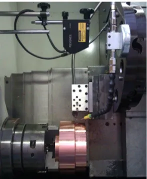
Cutting tests have been done on a 2-axis lathe Somab Transmab 400 at a cutting speed V of 250 m/min with c micro-lubrication (Total Valona MQL 3046).
The cutting forces have been measured with a piezoelectric dynamometer Kistler type 9121 and an amplifier Kistler 5019A. The signals have been digitised by a data acquisition card NI PCI-6221 (at a frequency of 2 kHz) and treated with DasyLab software.
Fig. 2. Experimental set-up
The local cutting geometries of the cutting inserts have been measured by stereovision from SEM photographs (Alicona Mex software).
The normal wedge angles n are approximately equal to 66° (
n17 ) and the edge radii r are between 11 and 17 µm.3. Effect of the workpiece radius on the cutting forces
3.1. Orthogonal cutting on disks
It has been shown by Germain [5] that, in the case of orthogonal cutting on disks, when the radius increases the cutting forces could increase for some cutting geometries. This has been supposed to be due to the enlargement of the clearance contact.
3.2. Cylindrical turning – Theoretical investigation
When finish cylindrical turning, in addition to the uncut chip thickness, the local cutting edge angle r (equal to
in the present case) and the radius of curvature of the workpiece in the plane Po (where is done the elastic recovery and the friction on the clearance face due to the first motion) evolve along the cutting edge too.This radius, called local effective workpiece radius, denoted W
o
R and shown on Figure 3, can be expressed by the Equation (4) according to Germain [14].
R
pa
fV
mZ
RR
r
W o maxR
( )
W oR
Fig. 3. Local effective workpiece radius when cylindrical turning
1 1 ( ) ( ) W o R R r cos cos (4)
At the cutting point corresponding to 90, the cutting configuration corresponds to orthogonal cutting on tube.
At 0, W o
R is equal to the workpiece radius, but it does not correspond to orthogonal cutting on disk because r is equal to zero.
3.3. Cylindrical turning tests
Five tests of cylindrical turning, with different feeds and depths of cut, have been done at different diameters. Some results are given in Table 1 and on Figure 4.
The depth of cut ap is small enough compared to r to have Ro maxW less than 1.3 times R. So, each group of five tests reflects the effect of a small range of radii.
It should be noted that, due to this reason, max is lower than 34.
Table 1. Measured forces when cylindrical turning in function of the workpiece radius
Test Parameters Measured forces for radius
87.5 R R mm RR12.5 mm N° f (mm/rev) p a (mm) max (°) c F (N) f F (N) p F (N) c F (N) f F (N) p F (N) 1 0.25 1 33.5 472 74 209 393 56 161 2 0.05 1 33.5 143 22 61 131 20 58 3 0.15 0.75 29 225 28 93 207 26 87 4 0.25 0.5 23.6 240 24 104 196 20 80 5 0.05 0.5 23.6 83 9 36 77 9 38
These tests have been conducted with a Sandvik RCGX1204M0-AL H10 (r 6 mm) insert mounted on a SRDCL2025M12 holder. The high nose radius r has been chosen because:
• The curvature of the active edge is small.
• It is possible to have low ratios ap/r with high cutting forces (noise reduction).
As the wear increases throughout the tests, a second insert – used only for two radii – has been used to verify that there is no change due to wear (Figure 4).
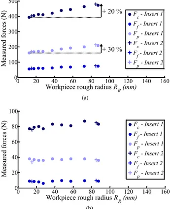
0 20 40 60 80 100 120 140 160 0 100 200 300 400 500 + 20 % + 30 %
Workpiece rough radius R
R (mm) M ea su red f or ce s (N) Fc - Insert 1 Ff - Insert 1 Fp - Insert 1 Fc - Insert 2 Ff - Insert 2 Fp - Insert 2 (a) 0 20 40 60 80 100 120 140 160 0 20 40 60 80 100
Workpiece rough radius R
R (mm) M ea su red f or ce s (N) Fc - Insert 1 Ff - Insert 1 Fp - Insert 1 Fc - Insert 2 Ff - Insert 2 Fp - Insert 2 (b)
Fig. 4. Measured forces vs. workpiece radius: (a) f0.25 mm/rev,
1
p
As it can be seen on Figure 4 (a), the increase of the forces can reach 30 %.
The comparison between the five tests shows that the effect of the workpiece radius is even more important as the feed and the depth of cut are high.
When ap increases, the growth of forces with the workpiece radius may be attributed to the evolution of
W o
R along the active cutting edge, which can affect the chip formation and the clearance contact.
Concerning the interaction between the radius and the feed, it could be due to the relative motion of the cutting edge and the machined surface. Indeed, at 0 the edge “slides” in parallel to the surface while at 90 the edge comes closer to the surface due to the feed rate. And so, the force acting on the edge and the clearance face due to the elastic deformation of the workpiece can increase, all the more since W
o
R is high.
It should be noted that the variation of forces due to the workpiece radius can be more important for higher
p
a , particularly around r ( max90 ); since, as previously mentioned, maxdoes not exceed 34 in this study.
In order to verify these assumptions concerning the effect of the orientation of the edge, elementary cutting tests have been conducted.
The goal of these tests, detailed in the next paragraph, is to reproduce what occurs on each segment of the discretised tool.
4. Elementary oriented cutting tests
Oriented cutting tests have been conducted using two types of configurations: either by cutting a tube or a corner as shown on Figure 5.
The second configuration allows testing very low values of r without risk of excessive bending, even vibrations, of the tube.
f
V Vf
(a) (b)
Fig. 5. Oriented cutting configurations: (a) Tube (r80 );
(b) Corner (r10)
The rectilinear cutting edges of Sandvik VCGX160404 AL H10 inserts have been used. The inserts are assembled with a SVJCL2020K16 body (modified to get r equal to 90°) or a SVHCR2020K16 (modified to obtain r 40 on a rear turret lathe).
In order to change the cutting edge angle r, the tool is oriented by a wedge (in red on the Figure 5).
4.1. Experimental procedure of tests on the corner
These tests consist in machining the corner of a cylindrical workpiece with a rectilinear cutting edge and an axial feed rate.
During the tests, three steps can be identified:
• The uncut chip thickness h and the width of cut b increase during the first revolution of cut.
• Then, b increases linearly over time and h is constant on the main part of the edge.
• Finally, h decreases due to the deceleration of the machine.
Because the global cutting forces evolve along the time, they should be divided by the width of cut b to be analysed. To be as accurate as possible, the gauge tool is made by electrical contact between the cutting edge and the workpiece edge, and the tool position is measured by a laser sensor Keyence LK-G82.
As the workpiece radius R is high (rough diameter of 183 mm) and the machine acceleration too (4 m/s²), the third step does not mask the second one in the present case. However, this point could be troublesome under different conditions, particularly when r is small because the feed becomes substantial.
4.2. Results obtained by the corner tests
Typical signal and chip obtained by these tests are shown on Figures 6 and 7.
0 0.1 0.2 0.3 0.4 0.5 0.6 0 200 400 600 800 1000 1200 1400revolutionFirst (Theoretical duration)
Linear increase of b Deceleration andretract of the tool
Cutting time t (s) F c
(N)
Fig. 6. Measured global cutting force Fc in function of time for
10
r
Fig. 7. Chip for r 10
and h0.25 mm
To be interpreted, the global forces, measured in the basis (Xm,Ym,Zm) linked to the dynamometer, have to be transformed into linear cutting forces expressed in the basis ( , , )o v h linked to the tool as shown on Figure 8.
p
F
fF
hF
( )
b t
fV
(
r)
h
f sin
r
Fig. 8. Global and local forces
A typical evolution of the linear force as a function of the width of cut b is presented on Figure 9. The first revolution corresponds to the part AC of the curve, with a scaling effect due to the small uncut chip thicknesses between the beginning and the point B.
0 1 2 3 4 5 0 100 200 300 400 A B C D E F G b (mm) f v (N/ m m )
Fig. 9. Linear cutting force fv (or fc) vs. the width of cut b for
10
r
and h0.25 mm
The increase between C and D could be attributed to side effects like burrs, which are not negligible for small width of cut. Then, there is a plateau (DE) which should correspond to the value obtained by the tube tests. The part between E and F corresponds to the deceleration, while the end of the evolution to the retract of the tool.
4.3. Effect of r on the forces
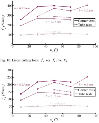
On Figures 10 and 11, the mean values of the linear forces fv (or fc) and fh – calculated on the plateau – for corner tests are compared to the values obtained by tube tests. The component fo is always near zero.
0 20 40 60 80 100 0 100 200 300 400 r (°) f v (N/ m m ) h = 0.25 mm h = 0.15 mm h = 0.2 mm h = 0.05 mm Corner tests Tube tests
Fig. 10. Linear cutting force fv (or fc) vs. r
0 20 40 60 80 100 0 50 100 150 200 250 300 r (°) f h (N/ m m ) h = 0.25 mm h = 0.15 mm h = 0.2 mm h = 0.05 mm Corner tests Tube tests
Fig. 11. Linear force fh vs. r
The graphics show that the new corner tests give forces levels in accordance with the tube tests. So, this method makes possible the realisation of elementary cutting tests without preparing tubes or disks specimens, which is a laborious work.
The trends observed on Figures 10 and 11 seem to consolidate the assumption that if the feed is high enough, the cutting edge angle affects the cutting forces.
However, the experimental results are very scattered, in spite of the attention given to the experimental procedure. It should be noted that, whilst the tube tests have been done with different inserts, all twelve corner tests have been conducted with a unique insert.
Furthermore, the results of the elementary tests do not show the only effect of r, since the change of this angle induces a modification of the effective radius RWo . However, this coupled effect is representative of the cylindrical turning, where both r and RWo vary along the cutting edge.
4.4. Observation of the tools
The four tube tests at h0.2 mm have been realised with four different inserts. As the feed is important, the contact between the clearance face and the machined surface was supposed to increase with r.
In order to confirm this statement, the four inserts have been observed by SEM. The backscattered electrons mode allows distinguishing the copper from the carbide of the insert as shown on Figure 12 (and confirmed by XDS analyses).
10 µm
Cu layer
Fig. 12. SEM image of the clearance face after cutting at r 50
and 0.2
h mm.
The contact lengths are between 3 and 8 µm and do not allow to draw conclusion about the effect of r on the tool-workpiece contact on the clearance face.
Due to the high clearance angle, it seems that the contact is located in the rounded cutting edge.
5. Conclusion
The new experimental methodology proposed through the corner tests is helpful to conduct elementary cutting tests without making thin specimens beforehand and avoiding vibrations during the cut.
Even if the tests have to be confirmed and completed, it seems that the introduction of the local cutting edge angle r and the effective workpiece radius RoW in the local model may improve the accuracy of the cutting forces model. Thereby, the modeling of the forces along a tool path with varying radii would be enhanced.
Future work on this topic will focus on the decoupling of the parameters r and RoW during the elementary cutting tests.
In-situ observations and post-mortem analysis of the clearance contact and the chip formation will also be developed in order to clarify the observed phenomena.
References
[1] Colwell, L.V., 1954, Predicting the Angle of Chip Flow for Single-Point Cutting Tools, Trans. of the ASME 76/2, pp. 199-204.
[2] Huang, Y., Liang, S.Y., 2003, Force Modelling in Shallow Cuts with Large Negative Rake Angle and Large Nose Radius Tools – Application to Hard Turning, Int. J. Adv. Manuf. Technol. 22/9, pp. 626-632.
[3] Armarego, E.J.A., Samaranayake, P., 1999, Performance Prediction Models for Turning with Rounded Corner Plane Faced Lathe Tools – I. Theoretical Development, Mach. Sci. Technol. 3/2, pp. 143-172.
[4] Bissey-Breton, S., Poulachon, G., Lapujoulade, F., 2007, Identification of Cutting Relations in High Speed Milling, Adv. in Integr. Des. and Manuf. in Mech. Eng., Springer, pp. 519-530. [5] Germain, D., 2011, Développement d’un modèle d’efforts de
coupe intégrant le contact en dépouille : Application au tournage de superfinition du cuivre Cu-c2, PhD Thesis (in French), Arts et Metiers ParisTech.
[6] Budak, E., Altintas, Y., Armarego, E.J.A., 1996, Prediction of Milling Force Coefficients From Orthogonal Cutting Data, J. Manuf. Sci. Eng. 118, pp. 216-224.
[7] Armarego, E.J.A., Epp, C.J., 1970, An Investigation of Zero Helix Peripheral Up-Milling, Int. J. Mach. Tool Des. Res. 10/2, pp. 273-291.
[8] Armarego, E.J.A., Cheng, C.Y., 1972, Drilling with Flat Rake Face and Conventional Twist Drills – I. Theoretical Investigation, Int. J. Mach. Tool Des. Res. 12/1, pp. 17-35.
[9] Koenigsberger, F., Sabberwal, A.J.P., 1961, An Investigation into the Cutting Force Pulsations during Milling Operations, Int. J. Mach. Tool Des. Res. 1, pp. 15-33.
[10] Venkatesh, V.C., Kattan, I.A., Hoy, D., Ye, C.T., Vankirk, J.S., 1996, An Analysis of Cutting Tools with Negative Side Cutting Edge Angles, J. Mater. Process. Technol. 58, pp. 351-361. [11] Kattan, I.A., Currie, K.R., 1996, Developing New Trends of
Cutting Tool Geometry, J. Mater. Process. Technol. 61, pp. 231-237.
[12] Noordin, M.Y., Venkatesh, V.C., Sharif, S., Elting, S., Abdullah, A., 2004, Application of Response Surface Methodology in Describing the Performance of Coated Carbide Tools when Turning AISI 1045 Steel, J. Mater. Process. Technol. 145, pp. 46-58.
[13] Khettabi, R., Songmene, V., Masounave, J., 2007, Effect of Tool Lead Angle and Chip Formation Mode on Dust Emission in Dry Cutting, J. Mater. Process. Technol. 194, pp. 100-109.
[14] Germain, D., Bissey-Breton, S., Fromentin, G., Poulachon, G., 2010, Force Modelling for Superfinish Turning of Pure Copper with Scale Effects, CIRP January Meetings.