High spectral purity microwave sources based on optical resonators
191
0
0
Texte intégral
Figure
![Fig. I. 13. From [33] : Phase noise of a 10GHz signal generated by a 330m-long active cavity based COEO Principle of passive cavity based OEO](https://thumb-eu.123doks.com/thumbv2/123doknet/2137158.8755/35.918.247.664.564.852/phase-signal-generated-active-cavity-principle-passive-cavity.webp)
+7
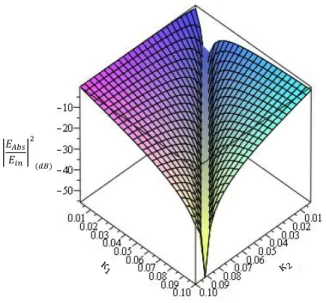
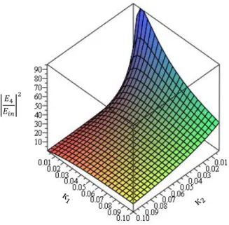
![Fig. II. 6. From [11]: MATLAB simulation results for and versus the FRR length](https://thumb-eu.123doks.com/thumbv2/123doknet/2137158.8755/54.918.216.702.406.731/fig-ii-matlab-simulation-results-versus-frr-length.webp)
Documents relatifs
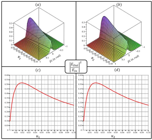
We present here the optimization of the performances of a fibre ring resonator and the experimental phase noise results we obtained for the OEO based on an optimized very
It can be used to modulate the phase of a continuous wave or a pulsed signal and several applications have highlighted various benefits of involving such modulation
