Science Arts & Métiers (SAM)
is an open access repository that collects the work of Arts et Métiers Institute of
Technology researchers and makes it freely available over the web where possible.
This is an author-deposited version published in: https://sam.ensam.eu Handle ID: .http://hdl.handle.net/10985/18210
To cite this version :
Simon GORECKI, Youssef BOUANAN, Judicael RIBAULT, Gregory ZACHAREWICZ, Nicolas PERRY - Including co-simulation in modeling and simulation tool for supporting risk management in industrial context - In: Simulation multiconference 2018, Hongrie, 2018-09-28 - Simulation multiconference 2018 - 2018
Any correspondence concerning this service should be sent to the repository Administrator : [email protected]
INCLUDING CO-SIMULATION IN MODELING AND SIMULATION TOOL FOR
SUPPORTING RISK MANAGEMENT IN INDUSTRIAL CONTEXT
(a)Simon Gorecki, (b)Youssef Bouanan, (c)Judicael Ribault, (d)Gregory Zacharewicz, (e)Nicolas Perry
(a), (b), (c), (d)Univ. Bordeaux, Lab. IMS, UMR CNRS 5218, 33400, Talence, France
(e)Arts et métiers, ParisTech, ENSAM of Bordeaux, France
(a), (b), (c), (d){firstname.lastname}@u-bordeaux.fr
ABSTRACT
Due to increasing complexity of engineered system of systems, development of software to design and support them must tend to be more and more concurrent and distributed. To more easily tackle these systems design, global problem is decomposed into several sub-ones where each sub problem is allocated and solved by different contributors. Each participant develops a fragment of the global solution that need after to be integrated with other ones. In this paper we present an extension to the UML/BPMN modeling and simulation tool: Papyrus. This module allows to factor complex tasks during the modelling step and simulation execution process. In detail, we propose to add risk management and other potential interruptions features to BPMN models and Simulation. This is made possible according to Functional Mock-up Interface standard, a co-simulation standard that define how to orchestrate components while simulation execution process.
Keywords: Model Driven Architecture; Co-Simulation; Functional Mockup-Interface; Risk Management.
1. INTRODUCTION
The Modeling & Simulation (M&S) concept is now a required step in any design of complex systems. It allows to early represent its behavior and interaction. The modeling phase describes a process and allows the development of an executable simulation that virtually designs our subject and anticipates its study. As technologies are growing, systems complexity increases, and makes system more difficult to model and simulate. Along with this growing complexity, risks, hazards, and threat must also be considered during the modeling process. Several research has been done about project risk management (Altuhhova, Matulevicius, and Ahmed 2013; Better et al. 2008). In this paper we propose a way to integrate them during the modeling and simulation phases without overloading models.
Modeling are one of the primary and most important steps in a project development process. In our case, we need a modeling language able to represent risk management. For that, the Unified Modeling Language (UML) is a general purpose, widely used for describing the different aspects of software and complex systems. It
offers several modeling notations to express not only the structure but the behavior of the modeled system. However, this language is also criticized for his low capacity to give precision to the system description. For this reason, the Object Management Group (OMG) has created the concept of UML profile which allows users to create their own UML specification. This UML specification will allow user to define his own language depending on his semantic subject, and provide it to the community: Systems Modeling Language (SysML), Use Case Diagram, etc.
This language is a viable solution for representing risks in a system description. Models will be designed and executed with Papyrus tool.
Papyrus is an open source UML/SysML/BPMN modeler of the Eclipse foundation that provides to users and developers a powerful tool for modeling UML models. Another interesting part of Papyrus tool is the execution of UML models due to fUML standards (Semantics of a Foundational Subset for Executable UML Models) allows by the MOKA engine (Guermazi et al. 2015). Our proposition in this paper consist in defining an extension to MOKA engine able to interrupt the simulation execution and do a request to an external simulation component through Functional Mock-up Interface (FMI). FMI Co-Simulation standard will allow us to relocate and factor complex tasks without overloading models.
In the case studied in this paper, an M&S tool is used in a semi-academic, semi-professional context: a French company has launched an innovative project to set up a solar power plant. This project deals with different domains and several simulations tools. All those domains will imply many constraints that must be taken into account during modeling and simulation phases. One of the main aspect we are working on is risk management. Indeed, in the renewable energy domain, many risks and issues must be taken in account by engineer at the modeling phase of the project such as weather issues impact, etc. Our contribution consists in adding a risk management module into an open source modeling and simulation environment: Papyrus.
2. BACKGROUND
In this section, recent contributions in co-simulation approach are briefly discussed first, efforts in risk management in process modeling are explained in 2.2, Papyrus, a UML modeler is described in 2.3, and finally, Functional Mock-up Interface standard is explained in 2.4 section.
2.1. Complex Systems simulation and co-simulation
The emergence of complex engineered systems that integrate both physical, software and network aspects are posing challenges in their design, operation, and maintenance. The current business climate and market pressure are forcing the design of systems to be concurrent, interoperable, distributed and reusable. This is done in order to be divided between different teams and/or external suppliers, each with its own expertise domain and each with its own tools. Here comes the role of Distributed Simulation (DS): one simulation is divided into multiple sub functions (or models) from a large system. Each function is executed on a different computer possibly geographically distributed from others. From a general point of view, this solution divides complex problems into simpler modular sub problems, but also rises interoperability issues.
Modeling and Simulation (M&S) of complex systems requires the simultaneous consideration of several points of view. The system behavior has to be considered at different levels and scales. In addition, the study of these systems involves skills from different scientific, business and technical fields. The challenge is then to reconcile these heterogeneous points of view, and to integrate each domain models and tools (or subsystems) within a unified framework, orchestrated by an M&S process. Two of the most popular efforts going in these directions are FMI (Functional Mock-up Interface) and HLA (High Level Architecture).
HLA is an IEEE standard (IEEE Computer Society 2010) for distributed computer simulation systems (IEEE Computer Society 2003). In the HLA standard, a distributed simulation is called Federation (see Figure 1). A Federation is composed of several HLA simulation entities, called Federate, which can interact among them by using the Run-Time Infrastructure (RTI). The RTI represents a Federation execution backbone and provides a set of services to manage the communication and data exchange among Federates.
FMI (Functional Mock-Up Interface) (Blochwitz et al. 2012) establishes itself as a standard for model exchange and co-simulation of equational models. The FMI functions are used (called) by a simulation environment to create one or more instances of the FMU (Functional Mockup Unit) and to simulate them, typically together with other models. An FMU may either have its own solvers (FMI for Co-Simulation) or require the simulation environment to perform numerical integration (FMI for Model Exchange). It enforces some generic rules and a software interface to manipulate equational models and their numerical solver using a combination of XML-files and compiled C-code. On that interface,
any equational component can be embedded into an FMU (Functional Mock-up Unit) helping to solve the interoperability problem for the co-simulation of equational models. Then, the numerical resolution of a system can be performed by defining a set of communication points between the FMUs according to a trade-off between the accuracy of the simulation results and the performances of the co-simulation process (Camus et al. 2016). The FMI standard defines two interfaces: FMI for Model Exchange and FMI for Co-Simulation (Blochwitz et al. 2012). The FMU CS contains its own solver that will be built when generating the tool. The advantage of this model is to combine two or more simulation tools in a co-simulation environment. The exchange of data between the subsystems is limited to ”Communication Points”. Between two Communication Points, the subsystems are solved independently from each other by their individual solver. Within a master-slave view, slaves simulate sub-problems while the master is responsible for the coordination of the overall simulation and data transfer. Several tools are compatible with the FMI interface at Export/Import for both components FMU, Model-Exchange (ME) and co-simulation (CS). Example: JModelica, Dymola, LMS AMESim, EnergyPlus, CATIA, NI LabVIEW, Ptolemy II, etc.
2.2. Risk management in process modeling
The concept of risk is highly polysemous and supports a large number of definitions.
In the context of risk management, we can introduce a number of concepts revolving around risk and conditioned by the environment and the components of the project. The project risk is related to the occurrence of events, from internal or external origin, which may affect the achievement of the initial target.
The risk qualify the effect of these events on the achievement of project's objectives. The anticipation of these events via the factor's identification, internal or external, which are the cause, the evaluation of their impact on the project progress and the proposal of appropriate treatment actions are the purpose of risk management.
In literature, we observed most recurrent major steps in risk management that we can cite: identification, analysis, evaluation and treatment of risks. These keywords can be used in tools such as brainstorming guidelines in order to anticipate, minimize risks in a project. However, these methods are not much structured, mostly handle qualitative information and are frequently limited to user experience and point of view. In the following, we cite some relevant methods and tools that were proposed in literature to manage risks.
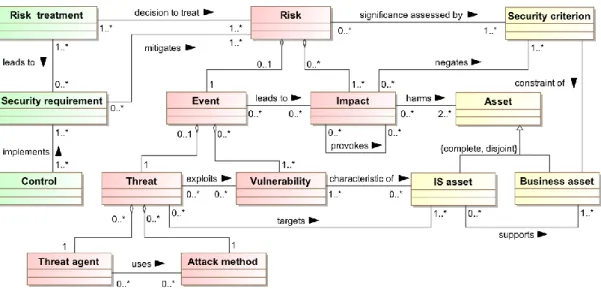
Information Systems Security Risk Management (ISSRM) methods and standards (according to (Dubois et al. 2010)) mainly consist of process guidelines that help identify vulnerable assets, determine security objectives, and assess risks as well as define and implement security requirements to treat the
risks. By using these methods one reduces the losses that might result from security problems. However, these methods generally offer quite poor modelling support. Instead, they usually resort to informal documentation in natural language and ad hoc diagrams. According to Figure 1, this analysis method allow user to identify and classify risks into three categories: - asset-related concepts are used to identify in a systems, or in a company, skills of the organization, and security risks that must be avoid. - risk-related concepts identify risk events and threat related to assets defined previously. - Risk-treatment concepts are defined depending on risks possibilities. They will represent the decision of how to treat the identified risks. A treatment satisfies a security need, expressed in generic and functional terms, and can lead to security requirements.
Business Process Modeling Notation Extension for Risk Handling was proposed in (Marcinkowski and Kuciapski 2012). The paper identify three different risk types: - Business-driven risks, strategic in nature aimed at protecting the business and keeping it accessible whenever and whoever in support of continuous business operations. - Data-driven risks, dealing with the availability of data and information in all of its different forms as used by the organization. - Event-driven risks, focusing on actual events that create risk to business continuity and viability. It propose to extend BPMN standard in order to modeling the several risks and handle it in three different ways: reduce it, retain it, avoid it, or transfer it.
2.3. Papyrus
Papyrus is the UML/SysML modeler of the Eclipse foundation. It provide tools for executing and debugging UML models. The execution part is handled by MOKA,
a fUML execution engine. Papyrus is based on Eclipse and is open source. In accordance with its primary goal to implement the complete standard specification of UML2, Papyrus provides an extensive support for UML profiles. It includes hence all the facilities for defining and applying UML profiles in a very rich and efficient manner. But, it also provides powerful tool customization capabilities similar to DSML-like metatools. This way, Papyrus is a tool enabling to gather the advantages of using a general purpose language such as UML2, but also those of DSML-based approaches.
2.4. FMI
The Functional Mock-up Interface (FMI) for Co-Simulation interface is designed both for the coupling of simulation tools (simulator coupling, tool coupling), and coupling with subsystem models, which have been exported by their simulators together with its solvers as runnable code. It is an interface standard for the solution of time dependent coupled systems consisting of subsystems that are continuous in time or time-discrete (Bastian et al. 2011; Blochwitz 2016; Sievert 2016). It provides interfaces between master and slaves and addresses both data exchange and algorithmic issues. FMI for Co-Simulation consists of two parts (Figure 2):
Co-Simulation Interface: a set of C functions for controlling the slaves and for data exchange of input and output values as well as status information.
Co-Simulation Description Schema: defines the structure and content of an XML file. This slave specific XML file contains “static” information about the model (input and output variables, parameters …) and the solver/simulator (capabilities …). The capability flags in the XML file characterize the ability of the slave to support advanced master algorithms which use variable communication step sizes, higher order signal extrapolation etc.
A component implementing the FMI is called Functional Mock-up Unit (FMU). It consists of one zip file containing the XML description file and the implementation in source or binary form (dynamic library). A master can import an FMU by first reading the model description XML file contained in the zip file. Coupling simulators by FMI for Co-Simulation hides their implementation details and thus can protect intellectual property.
Figure 2: FMU / FMI Concepts
3. CONTRIBUTION
3.1. Integrating risk management in modeling and simulation process
In order to integrate concepts described in section 2.2 one of the first solution was to implement risks treatment directly on models. However, risk management, particularly in renewable energy production domain imply different and complex methodologies and make the modeling too heavy and not systematic for the user.
Figure 3: Risks Modeling in BPMN
We can see on the top of the above Figure 3 a BPMN model of a simple database login action between a user and a system. The BPMN diagram at the bottom of Figure 3 represent the same upper model, with risk treatment taken in account: model can be very complex. Modeling and simulation a global solar energy production site with this method of risk management is too complex for user.
According to our subject, we must manage risks depending on several levels:
A risk can block a task, or it can slow it down (depending on a degree) as described in Figure 4.
Figure 4. Risk impact on a task
A risk can influence another one (increase or decrease its impact), it can form a causality chain such as described in Figure 5.
Figure 5. Risk causality chain
Several risks can be composed to generate or implicate a new hazard as described in Figure 6.
Figure 6: Composed Risk
Those risk management mechanisms appear too complex and heavy for being implemented directly on process model, also the rules can be dependent on the domain studied. It forms the reason why we propose to outsource them from papyrus model designer.
3.2. Proposition
We propose to define an extension to a modeling and simulation tool to include risk treatment separated from the main model. In our case, Papyrus, based on Eclipse, allow user to model UML diagram and, with the mechanism of UML-profiles, enable UML-based diagram modeling like SysML or BPMN. One of the advantages of using Papyrus as a modeling tool is the included MOKA execution engine which make possible to simulate fUML models.
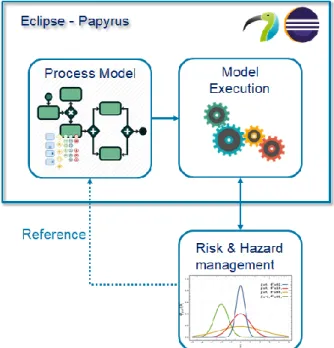
Our goal is to implement an ad-hoc system (Figure 7) to Papyrus in order to manage constraints, risks, and hazards during the simulation execution. This module is able to generate issues in the main system described by the process model. All the potentials issues are generated according to equations defined outside of the process model. This risk management extension is disconnected from the initial model in order to keep it clean (see section 4.1). The global simulation execution will react depending on hazards and constraints generated and referenced by the risk management module (as described in Figure 7).
Figure 7 represents the proposed architecture, we can observe the process model editor and the MOKA execution engine combined into Papyrus, and a connection to an external risk management module. This new module is connected to both Process Modeler and Moka Execution module to interact with them.
The objective of this proposition is to relocate and factorize complex tasks (risk management) during the simulation execution process. This may involve to use a co-simulation standard for insure communication between different external modules. Another way to communicate with the outside is to request web services API. According to this proposition, every type of complex systems can be relocated outside of the model.
Figure 7: Defining and Using Risks in M&S
FMI standard, propose two mechanism: the first is “simulation exchange”, the one that we are using in this paper. But the standard propose also “model exchange” mode which could be also implemented in this context. Using FMI as model exchange would means to modeling process into an external FMU and import it in the simulation. However, the MOKA engine could not execute fUML models described in external models.
4. BUSINESS CONTEXT
In our context, a company designing solar power plants has special needs. This project consists in installing solar panels fields to provide electricity and heat in a large area which is not powered so far. However, the transport of solar panels fields is extremely expensive. To reduce this cost/blow, they are designing a mobile factory which will be able to manufacture and assemble the solar panels on site. Rather than transporting finished products, only the mobile plant and raw materials would be carried out. The main challenges of this project are : the factory miniaturization to fit in the least transport containers (around 20) (Benama 2014), risks management (Rodney 2014) caused by low knowledge, and designing resistant
structure depending on the environment of the power plant (Piegay and Breysse 2015), (El Amine 2016). To guide the project and model the conception process, the company use Papyrus tool. The objective is to create several models for modeling and simulation of all workflow from the deployment of the mobile factory, to the management in real time of the production site. With the implementation of risk management module, the company aim at running simulations for every case possible in order to being able to anticipate and avoid problems.
5. REALISATION
According to (Guermazi et al. 2015), when the MOKA engine execute a fUML model, a mechanism named
visitors is executed at each steps of the simulation
process. This visitor can be surcharged and can execute java code at each steps of the simulation process. This is our entry point to the MOKA engine. During the execution process, at each task parsed by the engine, a visitor is called, we can test the name of the task and have access to his parameters (that is the “Reference” link between “Process Model” and “Risk & Hazard management” in Figure 7). During a global simulation process, the risk management module must know the name of each task of the model for allowing interactions with it.
The entry point of the MOKA engine is a java function. From it, we can integrate a co-simulation environment with Java-FMI. The library allow us to load an FMU file in order to interact with another simulation. In our context, we build a simple FMU which can generate errors in the process model according to a normal law (see Figure 8). In the same time, we are requesting weather information to a web service (OpenWeatherMap). Location is given in input of the API and it return to the visitor weather information. In our context, for a solar system, electricity production yield will be impacted depending on clouds and sunshine.
Figure 8: Requesting FMU and Web Service from Papyrus Visitor
Using MOKA engine to execute the models allows us the implementation of preconditions for tasks and resources.
They determine the conditions under which tasks or resources become available for execution in simulation process. Coupling an FMU component with precondition implementation offers a collaborative environment to control the execution of the elements (tasks or resources). For example, limiting elements start only under certain additional conditions calculated by other tools or environment.
As a first step, a new extension of the UML metamodel is created by adding new concepts (classes) and relationships (associations) using profile and stereotype mechanism. In our work we created a specialized object (Failure Element) that suspends the execution of an element (task or resource) based on the mean time between failure indicator and external variables (e.g. weather condition).
Figure 9: UML Profile describing the new concepts
FailableAction stereotype: Applied on Tasks (UML actions) with two attributes: (i) Mean Time Between Failure defines the average time (in hours) during an action can be executed before a failure occurs over a specified time period. (ii) Mean Time To Repair represents the average time required to repair a failed action (during this time the task can’t be executed). (iii) Notification of Default suspends the execution of the task depending on external variables and indicators.
FailableResource stereotype: Applied on Resources (UML Class) with three attributes: (i) Mean Time Between Failure defines the average time (in hours) during the resource can be used before a failure occurs over a specified time period. (ii) Mean Time To Repair represents the average time required to repair a failed resource (during this time the resource can’t be allowed or used by tasks independently from Availability constraints). (iii) Notification of Default suspends the availability of the resource depending on external variables and indicators.
The second step consists in generating the source code of the profile using the Eclipse Modeling Framework (EMF). The code generator for EMF models can be adjusted and in its default setting. It provides change notification functionality to the model in case of model
changes. EMF generates interfaces and a factory to create object.
Figure 10: Code generated using EMF
Then, we customize the execution engine by adding the implementation of the new execution engine which associate new Advices to the execution visitors, interacting with a FailureManager. The FailureManager centralized class counting the number of FailableElement executions and activating failures. We also add the implementation of the two advices (advice for FailureResource and advice for FailureAction). The first advice is associated to tasks which use Resources with FailableResource stereotype. It will ask to the failure manager if a task can start or finish and it =will also execute additional start/finish actions for a given task. Concerning the second advice, it is associated to Tasks with the FailableAction stereotype. It verify also on the failure manager if a task can start or finish and is executes additional start/finish actions for a given task. The part that allows to import an FMU and to execute it is implemented within these advices.
6. CONCLUSION
In modeling and simulation domain, many efforts are done to increase reusability and creating bridges between technologies. In this paper we presented a contribution to extend Papyrus execution engine for FMI co-simulation in the context of risk management. The paper demonstrate also the link between BPMN models to risk description. Then these risks characteristics are used at the simulation step.
However, many aspects must be improved for our contest. It is necessary to declare risks and hazards equations linked to our model. Efforts must be done to increase usability of this extension for enable model exchange aspects of FMI.
7. REFERENCES
Altuhhova, Olga, Raimundas Matulevicius, and Naved Ahmed. 2013. “An Extension of BPMN for Security Risk Management.” International Journal of
Information System Modeling and Desigh, January,
pp 93-113.
Bastian, Jens, Christoph Clauß, Susann Wolf, and Peter Schneider. 2011. “Master for Co-Simulation Using
FMI.” Proceedings of the 8th International
Modelica Conference, March, 115–20.
Benama, Youssef. 2014. “Supporting Make or Buy Decision for Reconfigurable Manufacturing System, in Multi-Site Context.” Ajaccio, France, September, 150–58.
Better, Marco, Fred Glover, Garry Kochenberger, and Haibo Wang. 2008. “Simulation Optimization Applications in Risk Management.” International
Journal of Information Technology & Decision Making, Vol. 7, No. 4, 2008, World Scientific
Publishing Company edition.
Blochwitz, Torsten. 2016. “Functional Mock-up Interface for Model Exchange and Co-Simulation.” https://www.fmi-standard.org/Downloads.
Blochwitz, Torsten, Martin Otter, Johan Åkesson, Martin Arnold, Christoph Clauss, Hilding Elmqvist, Markus Fredrich, et al. 2012. “Functional Mockup Interface 2.0: The Standard for Tool Independent Exchange of Simulation Models.” Proceedings of
the 9th International Modelica Conference, Munich, Germany, January, 173–84.
Camus, Benjamin, Virginie Galtier, Mathieu Caujolle, Vincent Chevrier, Julien Vaubourg, Laurent Ciarletta, and Christine Bourjot. 2016. “Hybrid Co-Simulation of FMUs Using DEV&DESS in MECSYCO.” Symposium on Theory of Modeling &
Simulation, Pasadena, USA, January, 1–8.
Dubois, Eric, Patrick Heumans, Nicolas Mayer, and Raimundas Matulevicius. 2010. “A Systematic Approach to Define the Domain of Information System Security Risk Management, Edit Dubois, Patrick Heymans.” Intentional Perspectives on
Information Systems Engineering, 2010.
El Amine, Mehdi. 2016. “Integration of Concept Maturity in Decision-Making for Engineering Design: An Application to a Solar Collector Development.” Springer-Verlag, London, October, 235–50.
Guermazi, Sahar, Jérémie Tatibouet, Arnaud Cuccuru, Saadia Dhouib, and Sébastien Gérard. 2015. “Executable Modeling with FUML and Alf in Papyrus: Tooling and Experiments.” EXE MoDELS, 2015.
IEEE Computer Society. 2003. IEEE Recommended
Practice for Distributed Simulation Engineering and Execution Process.
IEEE Computer Society. 2010. IEEE Standard
1516-2010 for M&S - HLA - Framework and Rules.
http://ieeexplore.ieee.org/stamp/stamp.jsp?arnumb er=5553440.
Marcinkowski, Bartosz, and Michal Kuciapski. 2012. “A Business Process Modeling Notation Extension for Risk Handling.” International Conference on
Computer Information Systems and Industrial Management, September, 374–81.
Piegay, Nicolas, and Denys Breysse. 2015. “Multi-Objective Optimization and Decision Aid for Spread Footing Design in Uncertain Environment.”
Geotechnical Safety and Risk 5, Rotterdam, the Netherlands, October, 419–24.
Rodney, Elodie. 2014. “Integrating Risks in Project Management.” 16th International Dependency and
Structure Modelling, Paris, June, 419–24.
Sievert, Nicke. 2016. “Modelica Models in a Distributed Environment Using FMI and HLA.”
8. AUTHOR BIOGRAPHIES
SIMON GORECKI is Ph.D. Student at University of
Bordeaux in IMS Lab. Domain research is about simulating process with distributed simulations and HLA (High Level Architecture). His email address is
YOUSSEF BOUANAN is Postdoctoral researcher at
University of Bordeaux. He received his Ph.D. degree in Production Engineering from University of Bordeaux, France. His research interests include M&S Theory, agent-based model and workflow. His email address is
JUDICAEL RIBAULT is a Ph.D. freelance software
architect and associate researcher at University of Bordeaux and IMS Lab. His email address is
GREGORY ZACHAREWICZ is Associate Professor
HDR at University of Bordeaux and IMS Lab with both competences in enterprise engineering and M&S. His email address is [email protected]
NICOLAS PERRY is Full Professor at ParisTech
ENSAM of Bordeaux. Domain research is about system engineering, product process integration and green manufacturing. His email address is