Science Arts & Métiers (SAM)
is an open access repository that collects the work of Arts et Métiers Institute of
Technology researchers and makes it freely available over the web where possible.
This is an author-deposited version published in: https://sam.ensam.eu
Handle ID: .http://hdl.handle.net/10985/12056
To cite this version :
Elise GRUHIER, Robin KROMER, Frédéric DEMOLY, Nicolas PERRY, Samuel GOMES -Transformable product formal definition with its implementation in CAD tools - In: Product Lifecycle Management, Espagne, 2017-07-12 - Product Lifecycle Management - 2017
Any correspondence concerning this service should be sent to the repository Administrator : [email protected]
Transformable product formal definition with its
implementation in CAD tools
Elise Gruhier1*, Robin Kromer2, Frédéric Demoly3, Nicolas Perry1, Samuel Gomes3
1Arts et Métiers ParisTech, I2M, CNRS UMR 5295, FR-33405 Talence, France 2IRT Saint Exupéry, I2M, CNRS UMR 5295, FR-33405 Talence, France 2ICB, UMR 6303, CNRS, Univ. Bourgogne Franche-Comté, UTBM, F-90010 Belfort, France
Abstract. Nowadays products extend their capabilities towards changing their configurations in order to cover multiple usage needs. They may be named transformable products and have not been taken into consideration in early design stages yet. In this paper, a proactive definition of the product is provided with transformation intrinsic properties. The formalization leads to an architecture. This enables developing a transformable product from two ordinary non-evolving objects. Different configurations and transformation processes have been set and implemented within a CAD tool to design a transformable product. A new paradigm is thus initiated, which will lead to efficient and dynamic design of transformable product.
Keywords: Configuration management; Formal definition; Transformation; Evolving product; Skeleton-based design
1 Introduction
Current design methodologies have been developed to support designer’s activities in the definition of “static” product. Product is considered as static in the use phase, when no major evolution is undergone. However, static products are limited in performance [1], leading to the emergence of other kinds of product, such as mechatronical or transformable products. The paper focuses on transformable products, which are characterized by different configurations in the use phase. The transformable product is nowadays under investigation. In literature, few methodologies consider the evolutions related to the transformation stages [2]. Besides, tools are not currently suited to design transformable product [3]. Indeed kinematic scheme, part-to-part relationships graph and CAD tool do not give any information on the different states/configurations of the product during the design process. Therefore, a proactive design methodology taking into account the specific properties and constraints of transformable products needs to be developed, in order to design them efficiently. One of the requirement of this research work is to clearly state what are the transformations encountered by the product and how they could be formalized. Then, a dynamic CAD application taking into consideration the product evolution at the early design stages could be developed. Further investigations, such
as augmented reality, could be developed based on this work. In this paper, the objective is to propose a transformable product definition considering its evolution during the use phase. First, a brief literature survey presents transformation research works in design process. Then, formal mereotopological and skeletal definitions of transformable product are proposed and lead to an architecture implemented within CAD tools. Finally, in the context of collaborative and proactive design, the interest of these definitions is discussed in the case study.
2 Review on transformable product design methodologies
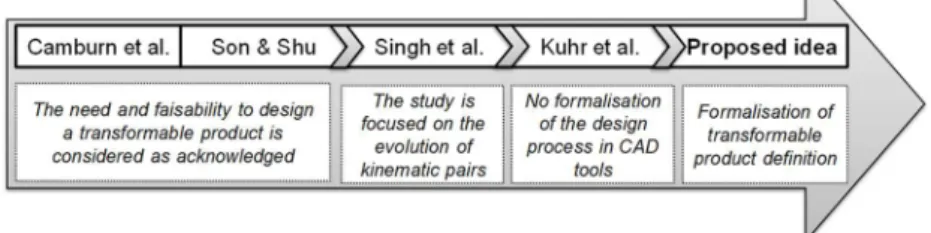
With the idea that transformable product will be commonly developed in the future, few research works have been undergone in the domain of design methodologies. Son and Shu [4] have compared the benefits of transformable products and standard products. Transformable products are seen as more efficient to overcome obstacles to “environment significant behavior”. Moreover, Camburn et al. [5] have developed indicators to decide when a transformable design is applicable depending on the category of transformer capacity (e.g. store, adjust and so on). Thus, the design of transformable products is justified by those advantages. Besides, Kuhr et al. [6] have created a methodology to determine the opportunities for transformation within each state based on concept opportunity diagrams. The idea was to facilitate the creation of transformable concepts. In addition, transformation principles and facilitators have been observed by Singh et al. [3]. They have listed existing embodiments, such as the expansion, exposition and fusion of products. Finally, Huang et al. [7] have also developed transformable 3D models. However, the product was more regarded as a puzzle, because they did not consider kinematic pairs.
The positioning of the proposed idea regarding other research works is detailed in Fig. 1. All these previous works have been developed at the early product development phase and sometimes even before the design phase. Besides, they have no link with CAD tools for direct application. This paper focuses on the understanding of the transformation and its formal definition to promote the design of evolving products (e.g. transformable products). Besides, a proper architecture has been proposed in order to give specific information to designers. The authors planned to define the architecture of transformable products during the design process in a dynamic way as they are perceived in the real world by users. Indeed, as stated by the CEO of Solidworks “large assemblies open and simulations complete in real-time as perceived by humans” is the next future of CAD tools [8].
3 Transformable product definition
3.1 Transformation principles
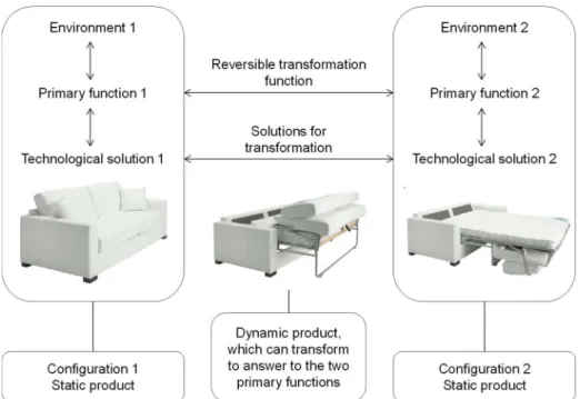
Transformable products are currently part of our everyday life and our dreams. For instance, every day Mary uses her cabriolet (transformed into a car with a roof if it is raining), her sofa (transformed into sofa-bed when a friend visits), wears her leggings (extended depending on her weight) and dreams to have a “Transformer” robot like in the Hollywood movie. Here, a transformable product is defined as being able to adapt to the environment, having multiple functionalities and being able to reversibly transform. Besides, it changes from one configuration related to one environment, to another configuration related to another environment (cf. Fig. 2). So, a transformation, including a change of primary functions, occurs from one configuration to another. During the transformation process, the product is evolving and can be considered as dynamic. On the contrary, during a configuration the product is fully single-state static. As such, transformable products cater to different user needs by performing more than one primary function [9]. Compared to single-state products, transformable products must meet several technical functions and make the link between parts, which are only useful for one configuration. So, the product architect and the designer must take into account more information and make more decisions in the early design stages [10].
Fig. 2. Introduction of a transformation function enabling the shift between both configurations
Two different transformations that can occur are intern and kinematic evolutions. The intern evolution represents a change (e.g. change of dimension or form) that impacts just one component. The kinematic evolution represents a change of kinematic pairs between two components. Here, the product definition is focused on kinematic evolution during the use phase.
3.2 Transformable product architecture
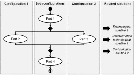
This section explains how from two different static products (based on routine design) the product architect can propose an architecture defining the novel transformable product. Fig. 3 introduces the transformation diagram composed of four columns. The first and third columns list parts, which are only used in one configuration. The second one represents parts belonging to both configurations. The last column gives the proposed technological solutions (e.g. kinematic pairs) chosen between two parts or the transformation technological solutions (e.g. transformation relationships described later). The product architect proposes an initial structure with parts and kinematic pairs corresponding to product evolution encountered in the use phase. A design process strategy is determined to aid the designer in configurations 1 and 2. The difficulty will be to implement this transformation diagram for a complex product. In this case, a design methodology will be required.
Fig. 3. Transformation diagram showing the link between both configurations and related technological solutions
3.3 Transformation mereotopological definition
Transformable products evolve during the use phase when the user wants a specific function. This evolution needs to be formally described, so as to be later applied in information or Computer-Aided Design (CAD) system. Therefore, mereotopological theory has been used to describe the evolution into spatiotemporal relationships (i.e.
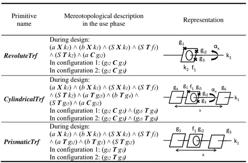
primitives). Mereotopology is a region-based theory enabling the formalization of two predicates (i.e. parthood and connection) with mathematical descriptions. The primitives have been named upon Trf (referring to Transformation) adding to the kinematic pair name. Table 1 shows some examples of mereotopological descriptions and their related representations. a and b are two parts in relation and S is the sketch to design a and b (b is the base part, which does not evolve). This enables designing in a top-down manner where parts are designing from a common relationship. X, C and T respectively stand for Cross, Coincident and Tangent mereotopological primitives. The skeletons k, f and g are described in the section below.
Table 1. Examples of some mereotopological descriptions of transformation primitives Primitive
name
Mereotopological description
in the use phase Representation
RevoluteTrf During design: (a X k1) ˄ (b X k1) ˄ (S X k1) ˄ (S T f1) ˄ (S T k2) ˄ (a C gi2) In configuration 1: (gi2 C g1) In configuration 2: (gi2 C g3) CylindricalTrf During design: (a X k1) ˄ (b X k1) ˄ (S X k1) ˄ (S T f1) ˄ (S T k2) ˄ (a T gi5) ˄ (b T g4) ˄ (S T gi5) ˄ (a C gi2) In configuration 1: (gi2 C g1) ˄ (gi5 T g4) In configuration 2: (gi2 C g3) ˄ (gi5 T g6) PrismaticTrf During design: (a X k1) ˄ (b X k1) ˄ (S X k1) ˄ (S T f1) ˄ (a T gi2) ˄ (b T g1) ˄ (S T gi2) In configuration 1: (gi2 T g1) In configuration 2: (gi2 T g3)
3.4 Transformation skeletons description
In this section, assembly, interface and use skeletons with its own parameters are described for each primitive. Assembly and interface skeletons are reused from previous works achieved in the assembly process [11]. Assembly skeleton (i.e. named k) ensures assembly positioning and interface skeleton describes geometric boundaries used to build a functional surface (i.e. named f). Use skeletons are introduced so as to be able to proactively define the product evolution in the use phase. These skeletons give information about both extreme boundaries of the move (i.e. g) and one intermediate use skeleton (i.e. gi), on which the product will be designed, navigating between boundaries. The intermediate skeleton can be instantaneously modified with defined parameters (i.e. last column of Table 2). Translation of a skeleton in the x, y and z axis, as well as rotation in the x, y and z axis are the two types of allowed parameters. The integration of those skeletons in CAD tools enables the designer to directly work in a dynamic context changing in
αx k1 f1 g1 k2 gi2 g3 x αx k1 f1 g1 gi2 g3 g4 gi5 g6 x k1 f1 g1 gi2 g3
regard to the chosen configuration. The idea was that the designer can choose one configuration and directly visualize the product in the chosen representation during design processing.
Table 2. Some skeletal descriptions of transformation primitives
Primitive name Assembly skeleton Interface skeleton Use skeleton with parameter RevoluteTrf k1 line
k2 plane
f1 surface g1, gi2, g3 points αx
CylindricalTrf k1 line f1 surface gg1, gi2, g3 points
4, gi5, g6 surface
x, αx
PrismaticTrf k1 line f1 surface g1, gi2, g3 surface x
4 Case Study
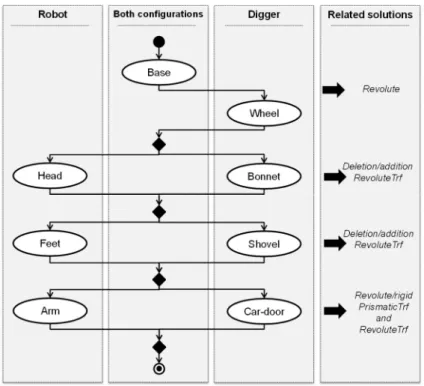
This section follows the three main steps: product architecture, mereotopological definition and skeletons description, for the dynamic design of transformable product. Here the objective is to formally define a “Transformer toy” having two distinct configurations, such as a mechanical digger and a fighting humanoid robot. The next step is to design this “Transformer toy” in a routine manner, as the geometry of both configurations is assumed to be known.
Fig. 4 presents the transformation diagram showing parts and their related solutions (i.e. mereotopological relationships or kinematic pairs). Here, the product architect has decided that the robot requires a head, feet and arms, as well as the digger needs a shovel, a bonnet and a car-door. Three of these six components (i.e. head, feet and arms) were necessary for the robot configuration and were useless for the digger configuration. In this case, the idea was to hide and show these components at the right time using a revolute pair. The shovel could also bring stability to the robot. Concerning the arm/car-door relationships, the idea was to use prismatic pair to move aside the arm from the body and a revolute pair to move the arm (cf. Table 4). Without the preliminary translation of the arm, the rotation would not be possible.
With this information, a transformation graph (cf. Fig. 5) containing all parts has been drawn. Some parts (e.g. bonnet and head) are linked, as one should appear in one configuration and be deleted in the other one. As such, the transformation graph integrates information from previous information with novel transformation primitives earlier defined. For instance, the product architect proposes a transformation part-to-part relationships graph. The kinematic pairs are defined for both configurations in the same graph. The transformation mereotopological description provides new information to the designer.
Fig. 5. Transformation part-to-part relationships graph for the “Transformer” toy Based on the transformation graph, assembly, interface and use skeletons are extracted from the definitions of primitives and integrated into a CAD tool (i.e. here Catia V5). Table 3 presents the skeletons focusing on the arm of the robot, as well as the parameters. The CAD file has been completely configured to have three different states, such as the configuration 1, the configuration 2 and the transformation step. The pink skeleton represents the “robot” configuration, the red one the “digger” configuration and the blue one the transformation, where parts are designed.
Wheel Arm Head Feet Bonnet Base Shovel RevoluteTrf RevoluteTrf Car-door RevoluteTrf PrismaticTrf RevoluteTrf Revolute RevoluteTrf PrismaticTrf RevoluteTrf
Table 3. Skeletons representation and behaviour according to the selected configuration Configuration Skeletons representation and parameters
Configuration 1
Transformation
Configuration 2
With these novel skeletons, the designer can create both parts (i.e. the arm/car-door and the base part of the robot/digger) as in Table 4 by modeling volume and shape. The CAD tree is presented in Fig. 6 with PrismaticTrf and RevoluteTrf, as well as two CAD bodies (i.e. Arm and Body) directly related, thanks to publications, to skeletons and the choice of the configuration. This CAD tree has been structured to highlight the research work. As such, the designer is aware that:
The prismatic pair to extract the arm from the body is limited by a surface (use skeletons of the PrismaticTrf from Table 2), whose distance has been previously chosen by the product architect thanks to the parameter x;
The revolute pair is constrained between 0 and 90°;
The robot can undergo the prismatic pair once the rotation (use skeletons of the RevoluteTrf) is one more time at the original point (limited with the α parameter chosen by the product architect).
Table 4. Focus on the arm of the toy transformation skeletons
Fig. 6. CAD tree of the arm/car-door design
Contrary to current static CAD tools, here several visions related to product configurations are presented. Consequently, the designer can choose, on which vision/configuration of the transformable product, he wants to work. This dynamically simulates the evolution of the product and enables checking the upholding of kinematic pairs thanks to novel use skeletons. For instance, the arm needed to be locked in mechanical digger configuration, so an added structure (i.e. highlighted parts in Fig. 7) was proposed by the designer.
Fig. 7. Locking structure from product architect’s transformation diagram
However, novel architectural product definition is limited because of current CAD tools. To go further, a new kind of interactive and dynamic CAD tools should be developed. Indeed, CAD tools are currently used for static design and not for the design of transformable or evolving products. This future CAD tool could have for instance a sliding cursor enabling visualizing both configurations and the intermediate steps of the transformation. Product design evolving in space and time is the key issue in the future.
5 Conclusions and Future Work
This paper has presented the first step of the research works motivated by literature review on transformation in the design phase. Compared to current works, here transformable products are designed from an architecture based on skeletons. The transformation primitives of the product have been formally defined using mereotopology and relying on skeletons. Indeed, assembly and interface skeletons have been reused from previous works and use skeletons have been created so as to make designers aware of boundaries of kinematic pairs move. Use skeletons are directly linked to parameters, which enable product architect to modify distances or angles at the preliminary stages of design. This product definition has also been integrated in CAD tools so as to design in a dynamic manner from a detailed architecture. It brings to the designer the opportunity to see the product evolution in the design phases.
In future work, this definition will be included in a design methodology so as to design transformable products. This novel methodology will ensure collaborative work through Product Lifecycle Management by linking the product definition to the transformation sequence, and will be integrated in CAD tools.
References
[1] S. Ferguson, A. H. Tilstra, C. C. Seepersad, and K. L. Wood, “Development of a changeable airfoil optimization model for use in the multidisciplinary design of unmanned aerial vehicles,” in ASME 2009 International Design Engineering Technical Conferences and Computers and Information in Engineering Conference, pp. 57–68.
[2] D. Kiritsis, “Closed-loop PLM for intelligent products in the era of the Internet of things,” Comput.-Aided Des., vol. 43, no. 5, pp. 479–501, 2011.
[3] V. Singh, S. M. Skiles, J. E. Krager, K. L. Wood, D. Jensen, and R. Sierakowski, “Innovations in Design Through Transformation: A Fundamental Study of Transformation Principles,” J. Mech. Des., vol. 131, no. 8, 2009.
[4] J. J. Son and L. H. Shu, “Role of transformation principles in enabling environmentally significant behavior,” in Leveraging Technology for a Sustainable World, Springer, 2012, pp. 563–568.
[5] B. A. Camburn, J. Guillemette, R. H. Crawford, K. L. Wood, D. J. Jensen, and J. J. Wood, “When
to transform? Development of indicators for design context evaluation,” in ASME 2010 International Design Engineering Technical Conferences and Computers and Information in Engineering Conference, 2010, pp. 249–266.
[6] R. Kuhr, K. Wood, D. Jensen, and R. Crawford, “Concept Opportunity Diagrams: A Visual Modeling Method to Find Multifunctional Design Concepts,” in ASME 2010 International Design Engineering Technical Conferences and Computers and Information in Engineering Conference, 2010, pp. 193–205.
[7] Y.-J. Huang, S.-Y. Chan, W.-C. Lin, and S.-Y. Chuang, “Making and animating transformable 3D
models,” Comput. Graph., vol. 54, pp. 127–134, Feb. 2016.
[8] B. Wang, “The Future of CAD 2019 as predicted by Solidworks,” 2009. Available:
http://www.nextbigfuture.com/2009/10/future-of-cad-2019-as-predicted-by.html.
[9] V. Kalyanasundaram and K. Lewis, “A fonction based approach for product integration,” J. Mech.
Des., vol. 136, 2014.
[10] B. Literman, P. Cormier, and K. Lewis, “Concept analysis for reconfigurable products,” ASME 2012 Int. Des. Eng. Tech. Conf., 2012.
[11] E. Gruhier, F. Demoly, K.-Y. Kim, S. Abboudi, and S. Gomes, “A theoretical framework for product relationships description over space and time in integrated design,” J. Eng. Des., 2016, vol. 27, no. 4-6, pp. 269-305.