A new assumed strain solid-shell formulation "SHB6" for the six-node prismatic finite element
Texte intégral
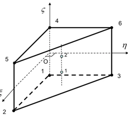
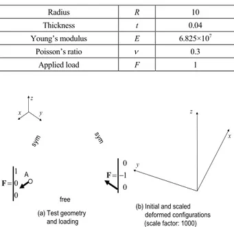
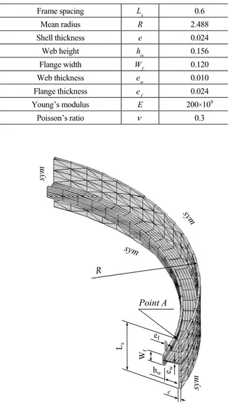
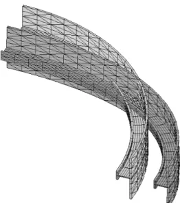
Figure


Documents relatifs
encoded by ABCB1 gene, has already been suggested to be a determinant of TAC PBMC disposition [4–6]. However, many other drug transporters, such as multidrug resistance proteins
The particular case of the aspect ratio ⌫=2 shows the following sequence of bifurcations as the Reynolds number is increased: 19 basic flow; steady state with m = 1, called mixed
While non-contributory pensions are spreading around the globe, Bolivia is still the only Latin American country with a universal old-age pension scheme.. Originally designed
Après explication de l’existence d’une forme galénique comprimé d’aspirine faible dose, 63,7% des patients (n=128) ont demandé à switcher leur Kardégic ®
Que el propósito de la CCEAG, como una comisión permanente del Comité Ejecutivo, es asesorar al Director General del Instituto Interamericano de Cooperación para la
A raíz de la pandemia del covid-19 y la creciente utilización del comercio electrónico, el MICI de Panamá fortalecerá las capacidades de las pymes en esta área.. Sumado a ello,
Ainsi l'émergence du masculin dans les études en sciences sociales sur l'espace domestique, dont je fais une rapide synthèse dans un autre article de cette revue, est
