Universit´e de Montr´eal
Unit´
e acad´
emique : D´
epartement d’informatique et de recherche
op´
erationnelle, Facult´
e des arts et des sciences
Ce m´
emoire intitul´
e
The load planning problem for double-stack
intermodal trains
Pr´
esent´
e par
Serena Mantovani
A ´
et´
e ´
evalu´
e par un jury compos´
e des personnes suivantes
Margarida Da Silva Carvalho
Fabian Bastin
Emma Frejinger
Teodor Gabriel Crainic
M´
emoire pr´
esent´
e `
a la Facult´
e des ´
etudes sup´
erieures et postdoctorales en vue
de l'obtention du grade de Maˆıtre d`es sciences (M.Sc.) en Informatique
c
R´
esum´
e et mots-cl´
es
Les trains qui transportent des conteneurs empil´es (en deux niveaux) sont un ´el´ement important du r´eseau de transport nord-am´ericain. Le probl`eme de chargement des wagons correspond un probl`eme op´erationnel couramment rencontr´e dans les terminaux ferroviaires. Elle consiste optimiser l’affectation des conteneurs des emplacements sp´ecifiques sur les wagons.
Ce m´emoire est centr´e sur un article scientifique traitant le chargement optimal publi´e dans
le European Journal of Operational Research (Volume 267, Num´ero 1, Pages 107-119, 2018).
Nous avons formul´e un mod`ele lin´eaire en nombres entiers (ILP) et apport´e un certain nombre de contributions. Premi`erement, nous avons propos´e une m´ethodologie g´en´erale qui peut traiter des wagons double ou simple empilement avec des “patrons” de chargement arbitraires. Les
patrons tiennent compte des d´ependances de chargement entre les plateformes sur un wagon
donn´e. Deuxi`emement, nous avons mod´elis´e les restrictions du centre de gravit´e (COG), les r`egles d’empilement et un nombre de restrictions techniques de chargement associ´ees certains types de conteneurs et/ou de marchandises. Les r´esultats montrent que nous pouvons r´esoudre des instances de taille r´ealiste dans un d´elai raisonnable en utilisant un solveur ILP commercial et nous illustrons que le fait de ne pas tenir compte de la correspondance conteneurs-wagons ainsi que des restrictions COG peut conduire une surestimation de la capacit´e disponible.
Mots-cl´es: transport; marchandises; conteneurs, planification de chargement, chargement de
Summary and keywords
Double-stack trains are an important component of the railroad transport network for con-tainerized cargo in specific markets such as North America. The load planning problem em-bodies an operational problem commonly faced in rail terminals by operators. It consists in optimizing the assignment of containers to specific locations on the train.
The work in this thesis is centered around a scientific paper on the optimization on load planning problem for double stack-trains, published in the European Journal of Operation Re-search (Volume 267, Issue 1, Pages 107-119) on 16 May 2018. In the paper, we formulated an ILP model and made a number of contributions. First, we proposed a general methodology that can deal with double- or single-stack railcars with arbitrary loading patterns. The pat-terns account for loading dependencies between the platforms on a given railcar. Second, we modeled Center of gravity (COG) restrictions, stacking rules and a number of technical loading restrictions associated with certain types of containers and/or goods. Results show that we can solve realistic size instances in reasonable time using a commercial ILP solver and we illustrate that failing to account for containers-to-cars matching as well as COG restrictions may lead to an overestimation of the available train capacity.
Keywords: Transportation; Freight; Containers, Load Planning, double-stack train loading; Intermodal Rail Terminals
Acknowledgements
Firstly, I would like to express my sincere gratitude to my advisors Teodor Gabriel Crainic, Emma Frejinger and Nicoletta Ricciardi for the continuous support during my study and related research, for their patience, motivation, and immense knowledge. Their guidance helped me to complete this thesis and to close this amazing journey.
Second, I gratefully acknowledge the close collaboration with personnel from the Canadian National Railway Company (CN). This research was funded by the CN Chair on Intermodal
Transportation at Universit´e de Montr´eal, Mitacs and a Collaborative Research and
Develop-ment Grant from the Natural Sciences and Engineering Research Council of Canada
(CRD-477938-14). I also acknowledge the support of Fonds de recherche du Qu´ebec through their
infrastructure grants.
Furthermore, I thank my family for their constant moral support, guidance and advises in anything I wanted to achieve in my life. Finally, I would like thank Gianluca for sharing this journey with me, for his continuous encouragement and love throughout these years.
Contents
Summary and keywords . . . ii
1 Introduction 1 2 Background on intermodal freight transport systems 3 2.1 Intermodal and multimodal transportation . . . 3
2.2 Transportation systems . . . 4
2.3 Container terminals . . . 7
2.3.1 Container port terminals . . . 8
2.3.2 Railway terminals . . . 9
2.3.3 Planning problems . . . 11
3 The load planning problem for double-stacked intermodal trains 13 3.1 Introduction . . . 13
3.2 The double-stack train loading problem . . . 15
3.2.1 Intermodal containers . . . 15
3.2.2 Intermodal railcars . . . 16
3.2.3 Loading containers on railcars . . . 17
3.3 Literature review . . . 20
3.4 Mathematical formulation . . . 22
3.4.1 Modeling containers-to-cars matching . . . 22
3.4.2 Modeling the COG restriction . . . 23
3.4.3 ILP formulation . . . 24
3.5 Numerical results . . . 26
3.5.1 Effects of containers-to-cars matching and COG restrictions . . . 27
3.5.2 Computational times . . . 31
3.6 Conclusions and directions for future research . . . 33
List of Figures
2.1 Process steps and decision levels in freight transport Source: Friedrich (2003) . . 5
2.2 Network with consolidation terminals/hubs. Source: Crainic and Kim (2007) . . 6
2.3 Operation areas of a seaport container terminal and flow of transport. Source: Steenken et al. (2004). . . 9
2.4 Example of a container terminal with an indirect transfer system. Source: Crainic and Kim (2007) . . . 9
2.5 Classification yard. Source: Boysen et al. (2013) . . . 10
2.6 Chicago rail terminal. Source: Google Earth. . . 11
3.1 Examples of container types . . . 15
3.2 Container stacking at 40 ft distance . . . 16
3.3 Five-platform double-stack railcar . . . 17
3.4 COG restriction . . . 19
3.5 Four height configurations relevant to the COG constraints . . . 24
3.6 Overview of the instance generation process . . . 31
List of Tables
3.1 Example of AAR Guide railcar series BN 63900 - 63909 type IBC 100 tons (*): 53 ft containers in top slot of platforms A, D and B only when a 40 ft container or none is loaded in top slot of platforms C and E. . . 18
3.2 Example set of loading patterns Kj for a one-platform railcar j (the rows
corre-spond to one pattern k ∈ Kj and columns to container lengths h ∈ H). . . 23
3.3 Descriptive statistics for the sets of loading patterns for railcars in the North American fleet . . . 27
3.4 Effects of matching problem and COG restrictions: number of loaded containers, number of used railcars and solution time for one-platform railcars . . . 29
3.5 Effects of matching problem and COG restrictions: number of loaded containers, number of used railcars and solution time for five-platform railcars . . . 30
3.6 Average computational time and average slot utilization for instances with di-verse characteristics . . . 32
Chapter 1
Introduction
The demand for goods has grown strongly over the past half century so that today an essential ingredient of a thriving national economy is a cost effective freight transportation system. This involves the use of multimodal, including intermodal, transportation options. Intermodal movements are those in which two or more different transportation modes are linked end-to-end in order to move freight and/or people from a point of origin to a point of destination. Intermodal freight transportation relies heavily on containerization due its several advantages: Containerization offers safety by reducing loss and damages of the product, by ensuring a faster exchange of modes and by decreasing transportation cost due to a smaller effort in moving the freight itself.
In the context of intermodal transportation, terminals play an important role by providing an interface between different transportation modes such as trains, trucks and vessels, in order to manage the sustained flow of containers from their origin to the final destination. Within a terminal there are several components to be managed, including the maritime side, the land side, the yard and the equipment. The activities in each component impact directly the performance of the others.
From a planning perspective, there are strategic, tactical and operational problems that arise at intermodal terminal. Especially at the operational level, typically the experience of planners plays an important role in the decision making process, and in many cases the policies are based on simple rules of thumb.
The need for optimization using methods of operations research in container terminal op-erations is becoming increasingly important. This is because the logistics, especially of large container terminals, is increasing complex when operating close to capacity and with quickly changing market requirements. Decision-aid tools based on optimization methods can provide terminal managers necessary information to take better decisions. This thesis focuses on an operational planning problem arising in intermodal rail terminals.
Trains are a widely used transportation mode for containerized cargo. Intermodal trains are composed of sequences of railcars, designed to carry single- or double-stacked containers. Railcars differ on attributes such as the number and the length of platforms, in turn composed of different slots, and the weight holding limit. Loading rules may not be derived regardless those differences. By nature, they can carry many more containers inland than trucks while being cost effective compared to airplanes. Relative to single-stack trains, double-stack trains have an increased carrying capacity as they allow the placement of two containers, one on top of the other, rather than a single one. Double-stack trains are more rare, but they are extensively used in some large markets like North America.
In this context, the Load Planning Problem (LPP) addresses the problem of loading the containers on the railcars that form the departing train. Load planning aims to find an as-signment of stored containers to specific railcars. With this thesis, the goal is to present a
general methodology that addresses the load planning problem for intermodal trains that can deal with single- or double-stack railcars as well as arbitrary containers-to-cars matching rules. Terminals represent the backbone of the entire international chain, and thus we aim at improv-ing their efficiency through a general methodology that can be used by terminal operators as a decision-support-tool for addressing the load planning problem.
In the literature, most of the studies focus on the single-stack load planning problem, where the loading is simple. The authors aim at deriving loading plans such that handling costs (e.g. Corry and Kozan, 2008) in the yard or train set-up costs (Bruns and Knust, 2012) are minimized. To the best of our knowledge, Lai, Barkan and ¨Onal (2008) is the only study on the double-stack load planning problem. A number of crucial aspects are however ignored, which make the problem challenging. First, they address the matching among containers and railcar types without considering platform dependencies, ignoring the cases when loading may be constrained by the railcar sequence. Moreover, the problem is studied without accounting for center-of-gravity restrictions and stacking rules.
We contribute to the existing literature by providing a general methodology that can address the load planning problem in all its crucial operational constraints and restrictions. Given a set of containers stored in a terminal and a departing train, the problem is to select the optimal set of containers to load and the optimal way of loading them, using the maximum of the available capacity. In our research we address the problem for double-stack trains, where the load planning problem is more challenging because of a number of loading rules that depend on container and railcar characteristics, and on the way they match together. The size, the location of the load-bearing along the length of the container, the type (e.g., tanker and dangerous containers have restrictions with respect to the position in the stack they may occupy) of containers determine how containers can be stacked.
The remainder of the thesis is articulated as follows: In Chapter2, we present the extensive framework of intermodal freight transportation where terminal fits, to the seaports and the railway yards. We describe the container terminals in2.3, giving an overview of what terminals
are and which equipment are needed. Section 2.3.1 provides an overview of the sea ports and
section 2.3.2 of the yard terminals. In section 2.3.3 we discuss the problems that arise at
container terminal, together with the reasons that encourage this research. Chapter3presents the research paper on the load planning problem for double-stack intermodal trains published
in the European Journal of Operational Research. Chapter 4 concludes on the thesis’ findings
Chapter 2
Background on intermodal freight
transport systems
2.1
Intermodal and multimodal transportation
In this section, we broadly discuss the intermodal freight transportation. Terminals, which are the principal entities of our study, play indeed an important role in a larger and complex intermodal freight transportation network.
The demand for goods has grown strongly over the past half century so that today an essential ingredient of a prosperous national economy is a cost-effective freight transportation system. This involves the use of multimodal, including intermodal, transportation. Even if the transportation could be of passengers or of freight, we focus on the latter.
Intermodal transportation relies heavily on containerization due its several advantages, such as the increase of the safety by significantly reducing loss and damage, the gain in the speed in performing transfer operations at terminal, the flexibility in the transport of products of various types and dimension and so on. The result is a most profitable flow of cargo, which is not damaged easily but it is simple to control and to schedule.
A container, as defined by the European Conference of Ministers of Transport (2001), is a “generic term for a box to carry freight, strong enough for repeated use, usually stackable and fitted with devices for transfer between modes”. Containers are large, metal and uniform boxes, that are used to transport goods from one destination to another one and with a standardized dimensions: A standard container is the 20-foot box, which is 20 feet long, 8’6” high and 8 wide. It is referred to as a twenty-foot equivalent unit (TEU). Containers are either made of steel, for maritime transport, or aluminum, for domestic transport. In the recent years, they have got a great importance especially in international maritime freight transportation.
Intermodal movements are those in which two or more different transportation modes are linked end-to-end in order to move freight and/or people from point of origin to point of destination. Intermodal freight transport is the term used to describe the combination of at least two modes of transport into a single transport chain, without a change of container for the goods, with most of the route traveled by rail, inland waterway or ocean-going vessel, and with the shortest possible initial and final journeys by road. Despite the growing emphasis being placed on intermodal transportation by government and industry, a consensus definition of intermodal transportation does not exist. According to Jones et al. (2000), “a large number of definitions are present in the research literature, suggesting that a fundamental interpretation of this term does not currently exist”.
European Conference of Ministers of Transport on 1993 described Intermodal freight trans-port such as the movement of goods in one and the same loading unit or vehicle which uses successive, various modes of transport (road, rail, water) without any handling of the goods
themselves during transfers between modes.
Contrary to conventional transportation systems, intermodal transportation aims at inte-grating various modes and services of transportation to improve the efficiency of the whole distribution process, in order to create a seamless journey, where transitions between modes occur smoothly with minimal delay. In fact, according to the U.S. Department of Transporta-tion (2006), the value of the multimodal shipments, increased from about $662 billion to about $1.1 trillion in a period of nine years (1993 - 2003). Because of its importance, intermodal transportation forms the backbone of world trade, and it exhibits significant growth.
It is important to underline the analogies and the dissimilarities between intermodal and multimodal transportation, as two different types of freight transportation. In fact, Intermodal and Multimodal are two terms often used loosely and interchangeably, but they have discernible differences:
• The International Multimodal Transport Association defines multimodal transport as the chain that interconnects different links or modes of transport air, sea, and land into one complete process that ensures an efficient and cost-effective door-to-door movement of goods under the responsibility of a single transport operator, known as a Multimodal Transport Operator, on one transport document. A multimodal transport contract is a single contract for carriage of goods by at least two different modes of transport, where a multimodal transport operator (MTO) assumes responsibility for the performance thereof as a carrier.
• Intermodal transport is a particular type of multimodal transport, wherein the goods are moved in one and the same loading unit, for example: containers. Intermodal trans-port uses more than one mode of transtrans-ports, where each of these modes has a different transport provider or entity responsible with independent contracts, and since the load-ing unit remains the same, the goods beload-ing transported, are themselves not handled each time there is a change of mode.
2.2
Transportation systems
Almost all types of freight carriers and terminal operators may be involved in intermodal transportation by operating an intermodal transportation system. Because of the interplay between producers and consumers and the distance that often divide them, demand for freight transportation comes up. In fact, the one who produces raw materials requires transportation services in order to distribute final goods to satisfy customers demand.
A supply network for freight consists not only of nodes and links but also of terminals nodes (freight hubs, logistic centers, shunting yards, warehouses) with specific characteristics
concerning capacity and transfer delay time. Figure 2.1 shows the process steps and decision
levels in freight transport as defined in the terminology on combined transport. At each decision level specific decisions concerning the movement of goods are required:
• The sender (shipper, consignor) demands the transport of goods-units and puts these goods-units in the care of others (freight forwarder, carrier) to be delivered to a con-signee. The sender will decide on a freight forwarder based on price and other factors like temporal constraints or reliability and generate the demand for transportation. • The freight forwarder organizes the shipping process. It provides and schedules unimodal
or intermodal transport chains for shipping the goods. For this it may subcontract carriers or provide its own carrier service.
• The carrier is responsible for the carriage of goods, supplying transportation service. The carrier answers the demand of transportation and provides the vehicles required for the transport along a unimodal section of the transport chain. The vehicles operate on the link infrastructure connection origin, hubs and destination.
• The driver steers the transport vehicle along a predefined tour. In case of road transport the driver may decide on the route between two points of the tour.
• The consignee is entitled to take delivery of the goods.
Figure 2.1: Process steps and decision levels in freight transport Source: Friedrich (2003)
Considering the type of service they provide, intermodal terminals and such facilities may be described as carriers as well. Terminals are, in this context, important for the operations of loading, unloading, transfer operations and consolidation, and their efficiency is vital for the performance of the entire transportation chain. The complex interactions between the actors is one reason why it is more complicated to model the decision processes in freight transport compared to passenger transport. The intermodal transport system can be viewed according to the different actors:
• We can look at it from the firm, that offers the service and that has problems related to the organization of activities. This is the point of view of the carriers (railway companies, shipping line, trucking companies and so on) and of the terminal itself, which needs to allocate resource to tasks in order to be as efficient as possible.
• We can look at it from the point of view of a individual container or more in general from the point of view of shippers, which want to ship containers in the best way as possible. Here, we find the carriers on the other side, providing services to shippers, who obviously want the service to be as cheap as possible, while having some guarantees on the service quality.
This combination of issues makes the intermodal transportation an hard topic. In our study, we take the point of view of a carrier, who offers the service at the best quality as possible,
by minimizing its own cost. As states in the Global Logistics Management book [Voortman
(2004)], “Logistics involves getting the right product to the right customer at the right time, in the right condition, at the right place, at the right price.”.
In an intermodal transport chain we have, on the one hand, consolidated transport where one vehicle or convoy serves to move freight for different customers with possibly different origins and final destinations, and, on the other hand, customized transportation carriers that provide dedicate service to each particular customers with possibly different origins and desti-nations. Full-load trucking is a classic example of customized transportation, that travels to the customer location, and once loaded, it moves to the destination, where it is unloaded. At the end of this process, the truck is repositioned. Customized transportation is not always the appropriate answer to shipper’s need, because of the relations and the trade-off between volume and frequency of shipping and the cost, the frequency and delivery time of transportation, that may dictate the use of consolidation services.
Consolidation can be a more attractive alternative. Freight consolidation transportation is performed by less-than-truckload (LTL) motor carriers, railways, ocean shipping lines, regular and express postal services, etc. Consolidation transportation carriers and most intermodal transportation systems are organized as so-called hub and spoke network, where shipments for a number of origin-destination points may be transferred via intermediate consolidation facilities, or hubs, such as airports, seaport container terminals, rail yards, truck break-bulk terminals,
and intermodal platforms. An example of an hub and spoke networks follows in Figure2.2. In
such systems, services are offered between a certain number of origins and destination points (local/regional terminal), represented by the numbered nodes. Taking advantage of economies of scale, low volume demands are moved first to an intermediate point, a consolidation terminal or hub, such an airport, seaport container terminal, rail yard, or intermodal platform. So, in hub and spoke networks, low volume demands are firstly moved from their origins to a hub where traffic is sorted and grouped, namely classified and consolidated.
Figure 2.2: Network with consolidation terminals/hubs. Source: Crainic and Kim (2007)
The aggregated traffic is then moved in between hubs by services and loads are transferred to their destination points from the hub by lower frequency services often utilizing smaller vehicles. When the level of demand is sufficiently high, direct services may be run between a hub and a regional terminal. This way to move freight between origins and destinations is an efficient utilization of resources and it is lower cost for shippers, but it can bring a higher amount of delays and a lower reliability due to the longer routes and the additional operations performed at terminals. All consolidation-based transportation modes involved in
intermodal transportation must provide efficient, reliable, and cost-effective services. In this context, carriers face a number of challenges which may be examined according to classical categorization of planning decisions, namely strategic (long-term), tactical (medium-term), and operational (short-term) level of planning and management of operations.
2.3
Container terminals
In this section we describe various types of container terminals. First, we give an overview of what they are and which equipment is needed. Second, we describe sea ports and rail yard terminals. Third, we present the class of planning problems which arise there, to provide the full context of our research.
An intermodal terminal provides an interface between different transportation modes such as trains, trucks and vessel in order to manage the sustained flow of containers from their origin to the final destination. It can be defined as any facility where passengers and/or freight are consolidated and deconsolidated. The focus of our study is only the freight terminals. Terminals may also be points of interchange involving the same mode of transport, which ensure a continuity of the flows but they are also important points of transfer between modes.
Three major attributes affect the performance of terminals:
• Location: The key factor of a transport terminal is obviously to serve a large concen-tration of population and/or industrial activities, representing a terminal’s market area. Specific terminals have specific location constraints, such as port and airport sites. New transport terminals tend to be located outside central areas to avoid high land costs and congestion.
• Accessibility: Accessibility to other terminals (at the local, regional and global scale) as well as how well the terminal is linked to the regional transport system. For instance, a maritime terminal has little relevance if it is efficiently handling maritime traffic but is poorly connected to its market areas through an inland transport system (rail, road or barge).
• Infrastructure: The main function of a terminal is to handle and transship freight or passengers since modes and passengers or cargo are physically separated. They have a physical capacity which is related to the amount of land they occupy and their level of technological, labor and managerial intensity. Infrastructure considerations are conse-quently important as they must accommodate current traffic and anticipate future trends and also technological and logistical changes.
Terminal costs represent an important component of total transport costs. They are fixed costs that are incurred regardless of the length of the eventual trip, and vary significantly between modes. They can be considered as: (i) Infrastructure costs: Include construction and maintenance costs of structures such as piers, runways, cranes and facilities (warehouses, offices, etc.); (ii) Transshipment costs: The costs of loading and unloading passengers or freight; (iii) Administration costs: Many terminals are managed by institutions such as port or airport authorities or by private companies (e.g., terminal operators). In both cases administration costs are incurred.
Terminal costs play an important role in determining the competitive position between the modes. Because of the high freight terminal costs, ships and rail are generally unsuitable for short-haul trips. Competition between the modes is frequently measured by cost comparisons. Reduced terminal costs would have a major impact on transportation system cost and the whole international trade. Due to that fact, the need for optimization using methods of operations
research in container terminal operations has become more and more important in recent years. This is because the logistics especially of large container terminals has already reached a degree of complexity that further improvements require scientific methods.
2.3.1
Container port terminals
A container port terminal provides transfer facility for containers among sea vessels and land transportation modes. Two interfaces make it up in order to guarantee a smooth flow of containers: The first one is the quayside where loading and unloading of ships take place, and the land side where containers are loaded and unloaded on/off trucks and trains.
Containers could be transshipped directly or can be stored in a storage area for facilitating
the decoupling of quayside and land side operation. Figure 2.3 shows the operations areas in
a seaport. Three main types of handling operations are performed at port terminal: • Ship operations associated with berthing, loading and unloading container ships. • Receiving/delivery operations from outside trucks and trains.
• Container handling and storage operations in the yard.
After its arrival in the port, the ship is assigned to a berth equipped with quay cranes able to load and unload containers. Different types of ships have to be served at the quayside, such as deep sea vessels and feeder vessels. Berth space is a very important resource in a container terminal and berth scheduling determines the berthing time and position of a container ship at a given quay. Quay-crane allocation is the process of determining the vessel that each quay crane will serve and the associate service time. Stowage sequencing determines the sequence of unloading and loading containers, as well as the precise position each container being loaded into the ship is to be placed.
During the unloading operation, a Quay-crane transfers a container from a ship to a trans-porter. Then, the transporter delivers the inbound (unloaded) container to a yard crane that picks it up and stacks it into a given position in the yard. This sequence of operations is called indirect transfer. Some terminals use a direct transfer system where the equipment used to move containers between the quay and the yard will also stack them.
For export (loading) operation, the process is carried out in the opposite direction. On the land-side, the receiving and delivery operations provide the interface between the container terminal activities and the external movements. A receiving operation starts when containers arrive at the gate of the terminal carried by one or several outside trucks or a train. When the outside truck arrives at the indicated transfer point, a yard crane lifts a container from the truck and stacks it according to the plan.
When containers arrive by rail, the rail cars are brought in the rail area where containers and documents are examined. Containers are then transferred by a gantry crane to a transporter, which delivers them to the yard and stacks them. The sea-side and land-side operations interact with the yard container handling and storage operations through the information on where the containers are or must be stacked within the yard. How containers are stored in the yard is one of the important factors that affect the turnaround time of ships and land vehicles. The space-allocation problem is concerned with determining storage locations for containers either individually or as a group.
Yard storage space is pre-assigned to containers of each ship arriving in the near future to maximize the productivity of the loading and unloading operations. Container handling and storage operations include the management and the handling of containers while they are in the storage space of the yard and thus occur between the receiving and delivery operations and the ship operations. Container-handling equipment performs the placement of containers
Figure 2.3: Operation areas of a seaport container terminal and flow of transport. Source:
Steenken et al. (2004).
into storage and their retrieval when needed. Yard cranes move along blocks of containers to yard bays to perform these operations. Planning these operations is part of the
equipment-assignment process, which allocates tasks to container-handling equipment. Based on the
quay crane schedule, one or two yard cranes are assigned to each quay crane for loading and unloading. The remaining yard cranes are allocated to receive and delivery operations. Terminal operators aim to assign and operate yard cranes in such a way that inefficient moves
and interference among yard cranes are minimized. Figure 2.4 shows an example of container
terminal.
Figure 2.4: Example of a container terminal with an indirect transfer system. Source: Crainic
and Kim (2007)
For the planning issues proper only of a maritime terminal, a fully description of the terminal operations and a wide literature review we refer to Steenken et al.(2004), Vis and De Koster
(2003), andCrainic and Kim(2007), while for the planning issues of the land side of a maritime terminal, we refer to the ones that we cite in the following section.
2.3.2
Railway terminals
A railway yard is a special transshipment node in a rail network where loads for trains are processed (collected, rearranged, unloaded, stored, loaded, picked up, etc.). It can be a terminal itself or it can be located in (or nearby) a seaport for moving freight with the hinterland. In this section we describe the basic structure of rail yards. For a broader literature review, we refer to Boysen et al. (2013).
Usually, an intermodal freight rail yard serves at least one of two main purposes in the railway system:
• A terminal can serve as an interface in intermodal transport, so that shipment can be interchanged between the rail system and another alternative mode of transportation (trucks, ships). Typically trains operate long-haul routes, while trucks act as link with the end nodes of an intermodal network, and then act on a short-haul transportation. So, a container that, for instance, must be moved from an origin to a destination where there is not a direct rail system, will be moved before by truck, that in general serve customers on the last mile, and then, once a railway terminal has been reached, it will be loaded into a train that will bring it to its destination.
• A terminal can be a hub node in a hub and-spoke network, so that containers are ex-changed between different trains. Economies of scale are generated because of the con-solidations of several blocks, that represent short groups of railcars having loads with different destinations grouped into few very long trains, which share part of the inter-modal trip. Again, railway transport oversees the long haul routes because of very high fixed costs.
According to Boysen et al. (2013) three different kinds of yards have been established,
depending on their generation (here we include yard types that are not limited to intermodal traffic): In traditional classification yards (first generation shunting yards, see Figure2.5) trains arrive onto a receiving tracks, railcars are typically pushed over a ramp (so-called hump), which redirects them toward classification tracks, where they are switched and addressed to departure tracks to outbound trains.
Figure 2.5: Classification yard. Source: Boysen et al. (2013)
Second generation railway yards are the traditional rail-roads terminals, where trains usually keep the railcars and only containers are moved by means of huge gantry cranes, that span several parallel tracks. In this type of yards, often, additional elements are present, such as areas for intermediate storage of containers and adjacent truck lanes for immediate transshipment from trains to trucks and vice versa. The main purpose of such yards is to serve as an interface between different modes of transportation. Lastly, third generation railway yard, which have a similar layout compared to second generation railway terminal, but are typical in a modern rail-rail transshipment, where a fully automated sorting system is employed, instead of conventional floor storage. Those kinds of terminal are still in a design phase, and hence we mainly focus on second generation railway yards with some mentions to the third generation terminal issues, since, instead, shunting yards are fundamentally different in structure and operations, and by the way are rarely part of modern container-based rail network.
A rail terminal, as already underlined, serves as interface of exchange between different transportation modes. Such terminals often feature a holding zone for trucks, a gate, and an office area for controlling access into and out the terminal. Trucks connecting the terminal with the hinterland arrive on parallel truck lanes, divided into driving and parking lanes, bringing into the terminal or out of the terminal, containers which have been moved by train. Trucks may arrive respecting some schedules or certain booking windows. For a given container, if its outbound train is not being loaded as the container arrives, it is moved to a storage area.
Trains are parked into parallel transshipment tracks of the terminal that cranes or reach stacker trucks can reach for loading and off-loading activities.
A terminal manager coordinates the activities in the three main interacting components of the terminal: rail track operations, storage yard operations and gate operations. Since a delay related to any type of operation affects the others, the objective of a terminal manager is to ensure that all the operations run as effectively as possible. For instance, a problem with storage yard operations can create delays both at the rail track and gate operations and have an impact on the terminal productivity and the quality of its services.
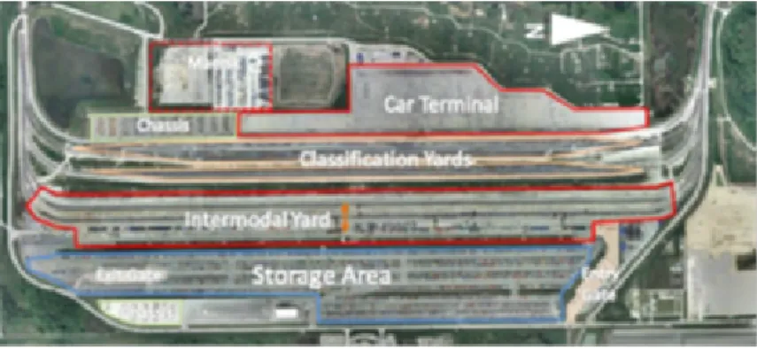
A real world example of a large-scale intermodal terminal is the BNSF Logistics Park Terminal, in the suburbs of Chicago (60 km southwest), which represents the largest intermodal
terminal in North America (Figure 2.6). It is a typical example of contemporary intermodal
terminal which includes all the components of a modern intermodal site in a typical rectangular shape. In addition to the common elements that are the intermodal yard, namely the storage area, chassis depots and the access gates (separate entry and exit locations), it also include classification yards and a car terminal.
Figure 2.6: Chicago rail terminal. Source: Google Earth.
2.3.3
Planning problems
Planning problems occurring at intermodal rail terminals can be divided into two categories: infrastructure planning (e.g., design) and operational planning (e.g., resource management) (Boysen et al.,2013).
Design. The first type of problems concern the long-term strategic planning intended to
an-swer questions such as which elements should compose the infrastructure, and how to integrate them into the system, in order to make the existing operations more efficient (Boysen et al.,
2013).
During the design phase of a terminal, critical decisions in regard to the dimensions of each terminal elements are made. For instance, the number of holding and transshipment tracks, the capacity of the storage and parking area, the number of technology and gantry cranes need to be determined. All these choices are interdependent and influence the yard performance.
Some planning decisions connected with railway terminals are:
• Infrastructure layout: It is the problem of configuring terminal infrastructure. Recon-struction activities may comprise the reduction, exchange or amplification of tracks, re-tarders or safety equipment, exchange or amplification of storage yard.
• Resource type and dimensioning: The problem is to find the type of equipment and the optimal number of resources to be used in the terminal. This is a strategic level decision, because the horizon in which the decision has an impact is about few years.
The existing literature on layout planning mainly consists of simulation studies, in order to anticipate yard performance for different terminal layouts. Within the existing literature on the broad range of issues regarding the layout of the terminal, refer to Boysen et al. (2013).
Operational problems. Once the layout of the terminal is fixed, several problems at
oper-ational level arise. Timetable of the trains is supposed to be fixed, and chosen at tactical level considering the whole network, hence it will not be accounted in the study of a single terminal. But the terminal manager, considering trains that arrive and leave the yard following a given schedule, needs to manage the flow of containers and railcars.
An operational problem worth of study is the assignment of an inbound train to a parking
position in the yard. Any parking position in the yard is characterized, according to Boysen
et al. (2013), by a vertical and an horizontal coordinate, and it must be assigned to any train that enters the transshipment yard. Firstly, the train is assigned to a vertical parking position of the yard, which relates to the actual track on which the train enters the yard, and then, an horizontal parking position of a train is assigned too, which refers to the slot in which the traction vehicle is positioned.
As soon as a train is parked, the unloading of all inbound containers can begin. Normally, some of the trucks that must take inbound containers are already in the yard, waiting for the unloading operations. In such cases, it can be preferable to transship directly a container from the train to the truck, rather than incurring in a double handling movement of moving it before to the intermediate storage area of the yard.
If a truck is waiting in the holding area, it is assigned to a parking position. This is normally a parking lane just beside the respective target railcar. This allows crane (or reach stacker) to move a container from the railcar to the truck directly.
If a container must be subject to a double handling, which is normally referred as a split move, it requires that a storage location close to the railcar is assigned to it, with the goal to reduce the crane operating time. The objective in this case, is to make the retrieval of that container as easy as possible once the truck arrives to the terminal. This could be done by organizing the containers based on updated information of the arrival times of the trucks, which could avoid future additional handlings of any blocking containers.
The processing of outbound operations is carried out similarly to the inbound operations but in a reversed order. Whenever a truck that is transporting an outbound container reaches the terminal, depending if the target train is already on the track or not, the truck is directed either to the storage area or besides one of the railcars of the target train, ready for a direct transfer.
An operational planning issue in this case is to determine, for each outbound container that reaches the terminal, which is its ideal position in the yard, in order to minimize the reshuffles of whole set of containers presented in the yard.
The aforementioned operational problems related to outbound containers are intrinsically connected to the load planning problem. The latter defines a plan identifying where to place each container on the available (double-stack) outbound railcars. This should be done such that crane handling costs are minimized while maximizing the utilization of available capacity and respecting a number of constraints. This thesis focuses on the load planning problem, central to effective operations at intermodal rail terminals.
Chapter 3
The load planning problem for
double-stacked intermodal trains
This chapter is published as: Serena Mantovani, Gianluca Morganti, Nitish Umang, Teodor Gabriel Crainic, Emma Frejinger and Eric Larsen, The load planning problem for double-stack intermodal trains, European Journal of Operational Research 267(1):107-119, 2018.
Author contribution
This chapter is based on a project in collaboration with the Canadian National Railway Com-pany. The work involved everything from mapping the decision processes at a terminal, docu-menting the operational constraints and objectives to mathematical modelling the problem and validation of the solutions with the operations at the company. Given the extent of the work, several people were involved over a quite long period of time. I was involved in all aspects of the scientific work: literature review, mathematical modelling, the design of the experimental results, the generation of results and the documentation of the work.
Abstract
This paper presents a general methodology that addresses the load planning problem for inter-modal trains. We propose a model that can deal with single- or double-stack railcars as well as arbitrary containers-to-cars matching rules. Moreover, we model weight and center of gravity constraints, stacking rules and technical loading restrictions associated with specific container types and/or contents. We propose an integer linear programming (ILP) formulation whose objective is to choose the optimal subset of containers and the optimal way of loading them on outbound railcars so as to minimize the resulting loading cost. An extensive numerical study is conducted. It shows that ignoring center of gravity constraints and containers-to-cars matching rules may lead to an overestimation of the train capacity and to select load plans that are not feasible in practice. We also show that we can solve realistic instances to optimality in reasonable computational time using a commercial ILP solver.
3.1
Introduction
Nowadays, an essential ingredient of a competitive economy is a cost-effective freight trans-portation system. Intermodal transtrans-portation is an important component of this system in which different transport modes are linked in order to move freight from a point of origin to a point of destination. Taking advantage of economies of scale, low volume demands are first
shipped to an intermediate point, a consolidation terminal or hub, where traffic is sorted (clas-sified) and grouped (consolidated). Then, the consolidated traffic is moved between hubs by efficient transport modes. In this paper we deal with intermodal railway transportation where containers are consolidated and transported by trains on the long-haul part of their trip. We focus on the North American market and on double-stack trains.
Intermodal transportation relies heavily on containerization because, in addition to de-creasing transportation cost, it ensures faster and safer handling as well as transfer between transport modes. Intermodal containers are steel frame boxes designed to move goods across the world using different transport modes without any re-handling of the cargo. Since 2005, the containerized worldwide traffic has increased from 382 to 684 million of TEU (Twenty
Foot Equivalent Unit) (CBRE Research, 2015) and, since 1990, North American ports have
seen container traffic grow by an annual average of 5.3% (International Association of Ports
and Harbors, 2015). This growth is placing a heavy burden on the entire consolidation-based transportation system, which must provide efficient, reliable and cost-effective services.
Terminals are major components of any intermodal transportation system and thus are critical to the entire international trade. They are special transshipment nodes that provide equipment and space where containers are processed, loaded, unloaded and stored to ensure a seamless transfer between different modes. Carriers, in our case railways, face a number of challenging planning issues, which may be examined according to the classical categorization with respect to the planning horizon, that is strategic, tactical, operational. In this study, we focus on the load planning problem, which is an operational problem arising at intermodal railway terminals.
Given a set of containers stored in a terminal and a sequence of railcars, the problem is to determine the optimal subset of containers to load and the exact way of loading them on an optimal subset of railcars while minimizing cost. We address this problem for
double-stack trains. This is a challenging problem because the load plan must satisfy a number
of complex loading rules that depend on specific container and railcar characteristics. For example, stacking rules depend on container sizes, weights, and contents and on Center Of Gravity (COG) restrictions. While the methodology expounded in this paper is general, the North American market is the main focus of our attention because it is particularly challenging. Indeed, there are in North America a large number of railcar types and several more container types and containers than the standard 20 ft (feet) and 40 ft.
As we detail in Section3.3, with one exception, the existing literature does not address the load planning problem for double-stack trains. Moreover, the simplifying assumptions that are adopted may lead to load plans that violate important loading rules and hence cannot be used in practice. For example, none of the studies model the COG restrictions. The objective of this paper is to propose a general methodology that addresses the load planning problem of double-stack trains taking into account all the different loading rules encountered in actuality. There are a large number of possible ways – so-called loading patterns – in which containers of different sizes may be loaded onto a railcar of a particular standardized type. The multitude of railcar types and the very large cardinalities of several of the associated sets of loading patterns is a key issue. We refer to this problem as containers-to-car matching. In connection with this problem, we make a number of contributions. First, we propose a general model that can deal with single- and double-stack railcars that can be of different types and subject to different loading rules. Second, our model accounts for additional loading constraints related to the specific container types, contents and weights as well as to COG restrictions. Third, we present an extensive set of numerical results based on a case study focusing on the North American market.
The numerical results indicate that our model provides an appropriate framework for solving very large instances of the load planning problem in reasonable time using a commercial solver.
They also demonstrate that failing to account for containers-to-cars matching as well as COG and stacking restrictions may lead to overestimations of the usable capacity and to suggesting load plans that are not applicable in practice.
The remainder of the paper is structured as follows. Section3.2describes the load planning problem in detail. Section 3.3 is dedicated to a review of the existing literature on the
assign-ment of containers to railcars and to highlight our main contributions. Section 3.4 presents
the ILP formulation of the load planning problem. Section 3.5 describes the content of the
empirical study and examines its results. Finally, Section 3.6 draws conclusions and discusses possible directions for future research.
3.2
The double-stack train loading problem
This section presents a detailed description of the load planning problem for double-stack trains. We examine the ways in which containers and railcars can be physically matched together and explain how these loading possibilities depend on the exact characteristics of the containers and railcars. We start by successively describing the intermodal containers and the rules for stacking them as well as the intermodal railcars. We then present the rules governing the loading of containers onto railcars.
3.2.1
Intermodal containers
Intermodal containers are characterized by (i) their size (length and height) (ii) their type (iii) their contents and (iv) their weight, filling level and weight distribution. In order to facilitate their handling, sizes are standardized. There are four ISO standard sizes used worldwide: 20 ft high cube, 40 ft low and high cube, 45 ft high cube (the height of low cube containers is 8 ft 6 in / 2.6 m whereas it is 9 ft 6 in / 2.9 m for high cubes). This paper focuses on the North American market, where there are two additional sizes of high cubes: 48 ft and 53 ft.
Figure 3.1: Examples of container types
For each size, containers are available in several standardized types. Some are illustrated in Figure 3.1. Ninety percent of the global fleet consists of general purpose containers, called “dry containers”, that are steel frame boxes with 6 solid sides (upper left in the figure). Sev-eral other types of containers are designed to transport goods for which dry containers are not suitable. For instance, reefers (refrigerated containers) or heated containers are designed to carry goods needing temperature control (bottom left in the figure). During transport, the reefers can either be connected to a genset (power generator set) supplying electrical power to
container without a roof (upper right), an open-side container and a tank container for the transportation of liquids (bottom right). While the designs of these containers are different, their sizes remain standard. Containers can carry hazardous materials in which case special restrictions usually govern their storage and transport.
Containers can be stacked one on top of another. In addition to rules governing the weights and the positioning of containers loaded onto railcars, the stacking of containers must conform to rules prescribing their relative position. In essence, the containers must be positioned so as to ensure that their load is transferred in accordance with the design of their steel frames. Specifically, the container above can be connected to the container(s) below with four Inter Box Connectors (IBC) designed for this purpose and the standard lengthwise distance between the connecting points where these couplings can be installed is 40 ft. This is illustrated in
Figure 3.2 where the thick lines indicate this 40 ft distance. Hence, a 40 ft container can be
loaded on top of two 20 ft but a 20 ft container cannot be loaded on top of a 40 ft one. Since the connecting points are symmetrically located from the mid-length of the containers, a longer container (45, 48, 53 ft) must be centered on top of a shorter one (40, 45, 48 ft) or on top of a pair of 20 ft containers.
Figure 3.2: Container stacking at 40 ft distance
Lastly, we assume that there exists a per container cost associated with the failure to load an available container standing for, e.g., customer penalties for late arrival and storage costs in the terminal.
3.2.2
Intermodal railcars
Intermodal trains consist of a sequence of railcars designed to carry single- or double-stacked containers. Intermodal railcars are characterized by their number of platforms and by the length, weight-carrying capacity and tare weight of each one.
Figure 3.3 illustrates a five-platform double-stack railcar. In accordance with the North
American industry standard, the front platform is named A, the rear B and the other platforms C to E from front to rear. Similarly, the platforms of a three-platform railcar are named A, C, B from front to rear, and so forth. Each double-stack platform has two slots: bottom and top. Costs are associated with the operation of a train and are incurred in the acquisition and maintenance of the locomotives and railcars, in purchasing fuel and employing crews (see e.g.
Bouzaiene-Ayari et al., 2014). We hence assume that there is a cost associated with leaving slots empty on outbound railcars.
Figure 3.3: Five-platform double-stack railcar
3.2.3
Loading containers on railcars
Trains are composed of blocks where a block in this context is a group of railcars that move between an Origin and Destination (OD) pair of terminals without being reclassified. The purpose of grouping railcars, with different OD terminal pairs, into blocks is to minimize the transfer from one train to another or the classification of individual railcars at intermediate terminals. The block plan is a tactical decision problem and the operational load planning problem is solved separately for each block.
Containers arrive to an intermodal rail terminal by trucks or by vessels. Upon their arrival, the containers are either classified according to the block on which they will travel and stored in the yard, or directly loaded on outbound railcars of this block. Since containers can arrive shortly before, or even during the loading operations, load plans must be computable in a short time (preferably within a few minutes).
The assignment of containers to slots must conform to a number of rules that depend on the characteristics of the railcars and the containers. We start by describing the rules that pertain to container size only. We refer to them as containers-to-cars matching rules. For the North
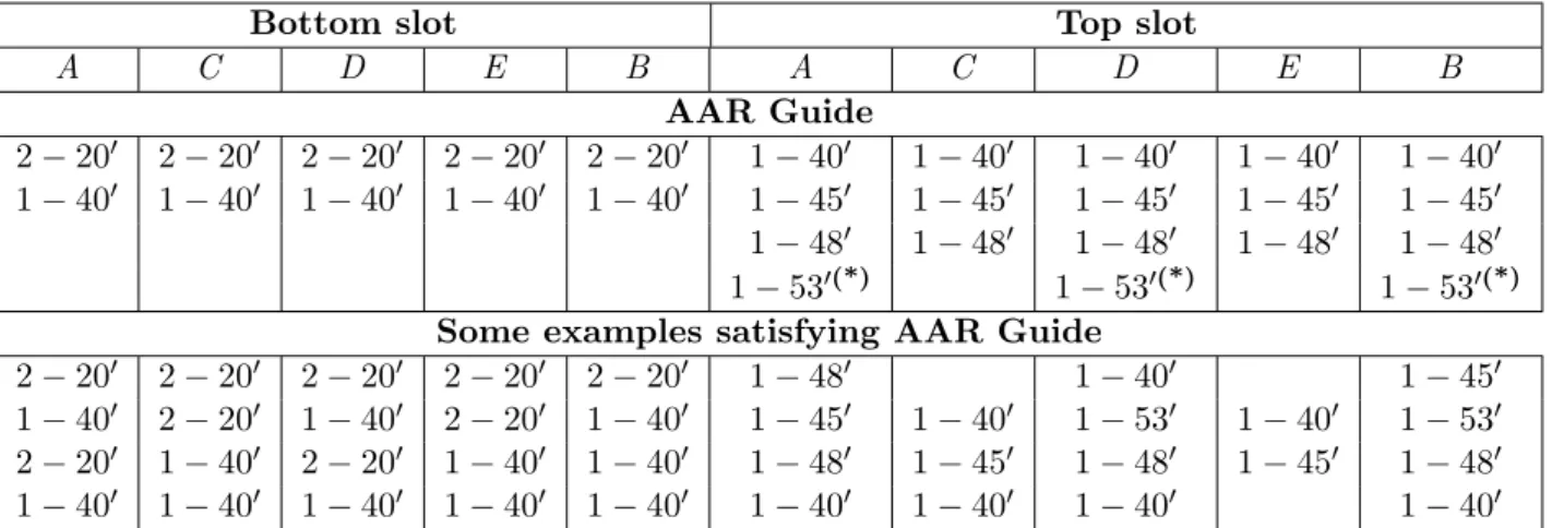
American market, the AAR Guide (Association American Railroads, 2014) provides for each
listed series of railcars a complete description of the combinations of container lengths that can be loaded in the bottom and top slots of each platform. Except for the bottom slots that can generally accommodate up to a pair of 20 ft containers placed end-to-end, slots can receive at
most one container. Table 3.1 provides an illustration for a five-platform railcar series. The
second block of rows is excerpted from the AAR Guide. It prescribes for each one of the five platforms (A-E) which container sizes can be loaded in the bottom and top slots respectively. Each row in the third block states one particular loading possibility, i.e. a loading pattern, satisfying the prescriptions of the second block.
The platform length for this series of railcars is 40 ft whence the bottom slots can accom-modate one or two 20 ft containers (2 – 200 in the table) or one 40 ft (1 – 400 in the table). The load in the top slot must conform to the stacking rules and to the space available. The space between platforms can in some cases be sufficient to allow the loading in the top slot of
a container exceeding the length of the platform. This is examplified in Table 3.1 where each
top slot can accommodate a 40 ft, a 45 ft or a 48 ft container and where the space between the platforms allows to load 53 ft containers in the top slot of platforms A, D and B, provided there is a 40 ft container or no container at all in top slots of platforms C and E (see table footnote). Crucially, these joint requirements imply that the containers-to-cars matching rules cannot be described for each platform separately.
Slots may also be left empty and an upper slot can be filled only provided the slot below is filled. Moreover, a top slot cannot be filled if there is a single 20 ft container loaded in the slot below. There are clearly several different ways in which to load a five-platform railcar so as to
satisfy the loading capabilities stipulated in the AAR Guide and the lower rows of Table 3.1
exemplify a very small number of them. For example, the last row describes a loading pattern where a 40 ft container is placed in every slot except in the top one of platform E. The latter
is left empty.
Bottom slot Top slot
A C D E B A C D E B AAR Guide 2 − 200 2 − 200 2 − 200 2 − 200 2 − 200 1 − 400 1 − 400 1 − 400 1 − 400 1 − 400 1 − 400 1 − 400 1 − 400 1 − 400 1 − 400 1 − 450 1 − 450 1 − 450 1 − 450 1 − 450 1 − 480 1 − 480 1 − 480 1 − 480 1 − 480 1 − 530(*) 1 − 530(*) 1 − 530(*) Some examples satisfying AAR Guide
2 − 200 2 − 200 2 − 200 2 − 200 2 − 200 1 − 480 1 − 400 1 − 450 1 − 400 2 − 200 1 − 400 2 − 200 1 − 400 1 − 450 1 − 400 1 − 530 1 − 400 1 − 530 2 − 200 1 − 400 2 − 200 1 − 400 1 − 400 1 − 480 1 − 450 1 − 480 1 − 450 1 − 480 1 − 400 1 − 400 1 − 400 1 − 400 1 − 400 1 − 400 1 − 400 1 − 400 1 − 400
Table 3.1: Example of AAR Guide railcar series BN 63900 - 63909 type IBC 100 tons (*): 53
ft containers in top slot of platforms A, D and B only when a 40 ft container or none is loaded in top slot of platforms C and E.
The assignment of the containers to the slots of the railcars is conditioned by the weights of the containers and the weight-carrying characteristics of the railcars. There are two main loading restrictions with respect to the weight of the load on a platform. First, the total weight of the containers loaded on a platform must be smaller than the weight capacity of the platform. Second, a condition pertaining to the height of the center of gravity must be satisfied. This expression is used in the North American railway industry with a meaning identical to that of the expression center of mass. Although it designates more generally the mean location of a distribution of mass in space, it is defined in the context of railway operations as the mean location of mass along the vertical axis of a platform. The AAR Guide states “...The COG for a double-stack car and the load in the platform must be less than or equal to 98 inches at top of rail. Reference Rule 89, Section C.2.e. in the AAR Field Manual ”. A failure to obey this rule would imply practically that the container placed in the top slot of the platform is too heavy in comparison with the weight of the container(s) placed in the bottom slot. This situation would be viewed as a risk factor to a derailment. While the actual COG depends on the filling level and the load distribution in the containers, the COG restriction stated in the AAR Guide relies on the assumption of a uniform weight distribution. In the case of a solid body with uniform weight distribution, the center of mass is the same as the centroid of the body. In this paper we follow the AAR definition of COG.
The COG restriction is expressed as an upper bound on the weight of the container in the top slot, given the characteristics of the container in the bottom slot. Figure 3.4 provides an illustration for a single platform. There are three solid bodies: the platform p, the bottom container i and the top container i0. Their centroids are illustrated with black dots and the associated heights from the top of the rail are denoted mp, mi and mi0, respectively. The
bottom and top containers are connected with IBCs. Under the assumption of a uniform weight distribution, the height of the COG m for the three solid bodies is
m = mpgp+ migi+ mi0gi0 gp + gi+ gi0
(3.1)
where gp is the platform tare weight and gi and gi0 are the weights of the bottom and top
containers respectively. According to the AAR Guide, m ≤ M where M equals 98 in (2.5 m).
rearranging (3.1) and using M instead of m and c instead of gi0 we obtain
c = gp(M − mp) + gi(M − mi) mi0− M
. (3.2)
Figure 3.4: COG restriction
Containers exist in a diversity of types carrying a diversity of contents and rules are attached to particular combinations of types and contents. These rules give rise to a number of additional constraints in the container loading problem. For the North American market we have identified six technical loading restrictions that apply to certain types of containers and contents or to combinations thereof:
1. Loading is restricted to railcars having a given minimum weight-carrying capacity (inde-pendently of railcar series). This restriction applies to containers whose weight is above a certain threshold and needs to comply with additional restrictions not captured by the weight-carrying capacity of a platform.
2. Loading is restricted to certain positions in the sequence of railcars (e.g., hazardous material).
3. Loading is restricted to high weight capacity railcars (only certain railcar series). 4. Loading in top slot is forbidden.
5. Loading in top slot and double stacking is forbidden.
6. Loading must be on a platform within a maximum distance from a specific container (e.g., for the reefers that must be connected to a genset).
This set of technical loading restrictions is sufficiently general to cover the specificities that we have identified thus far in relation with the North American railways. Additional technical loading restrictions might have to be defined in order to reflect new or presently unknown railway policies or country regulations.
In summary, we focus on the load planning problem: Given a set of containers stored in a terminal, a sequence of railcars, and the relevant constraints, determine the subset of containers to load and the exact way of loading them. The objective is to minimize the cost of unloaded containers and the cost of empty slots. A key performance indicator currently used to measure the efficiency of a load plan is the slot utilization, which measures the percentage
of the available slots on the railcars that are occupied in the load plan (Burriss, 2003). We note that we focus on a deterministic setting, and that we do not model the different handling costs associated with retrieving containers in the terminal. Our goal is to develop a general methodology, which can be used within a decision support tool that provides load plans to decision makers. We deal with all the loading rules and restrictions that arise for double-stack trains, by taking into account the multitude of containers and railcars types that exist in the North American market.
3.3
Literature review
The load planning problem may be viewed as a special case of the packing-cutting-knapsack
problems (Martello and Toth, 1990; Dowsland and Dowsland, 1992; Dyckhoff et al., 1997;
W¨ascher et al.,2007). The goals and the associated models are different in most cases, however. For example, in two- (Lodi et al., 2002) and three-dimensional packing (Crainic et al., 2008) one faces a much larger number of items than the number of available (or desirable) loading units (bins) and the dimensions of the items span a broad range of values from tiny to almost as large as the bin. One then focuses on identifying the “best” bin and the “best” position in the bin to load all items in as few bins as possible. In the rail load planning problem, on the other hand, bins - the railcar platforms - and the items - the containers - are fundamentally of similar dimensions, the positioning being determined by the physical configurations of both. The goal is then changed from packing as many items as possible into as few bins as possible to identifying the best combination (assignment) of given container dimensions and weights to the available railcars given technical loading constraints (e.g., total weight and COG). The cutting/packing setting closest to the problem we address is identified as the multiple identical
large object placement problem by W¨ascher et al. (2007), where the multi-platfom railcars
would be the more or less identical large bins, while the heterogeneous fleet of containers would correspond to the set of large items. There were no contributions to this problem class when the classification of W¨ascher et al. (2007) was published and we are not aware of any more recent ones either.
COG and load balancing concerns also arise when planning the loading of vehicles for other freight transportation modes, e.g., trucking, sea and air transportation. Each transportation mode has its own vehicle and operation characteristics, resulting in particular forms of these general restrictions. For example, the axle weight restriction for trucks may result in particular requirements for weight distribution when loading the containers before even the ocean segment of their trip (Lim et al.,2013). The distribution of weight, and thus of containers, is of capital importance for the stability of ships and airplanes. The COG of the vehicle thus becomes a hard safety constraint in ship stowage (Steenken et al.,2004;Stahlbock and Voß,2008) and airplane (Mongeau and Bes,2003), but while the number of container re-handles (at intermediate stops) is generally not relevant in the latter case, it is an element to be taken into account in the former case (Imai et al., 2006).
We open this overview of the literature relevant to the rail load planning problem by pointing to two surveys whose scopes extend to intermodal freight transportation activities in general: SeeCrainic and Kim(2007) for the planning of intermodal carrier and terminal operations, and
Carlo et al. (2014) for transportation activities in container terminals. Several studies focus on the train blocking problem (e.g., Bodin et al.,1980;Newton et al.,1998;Barnhart et al.,2000). For general views on the rail load planning problem per se, seeHeggen et al.(2016) for a recent classification of the existing literature and Boysen et al.(2013) for a comprehensive overview of the planning issues that arise specifically in railway yards, including the load planning problem.
Specifically in connection with the rail load planning problem, Feo and Gonzalez-Velarde