HAL Id: hal-01121217
https://hal.archives-ouvertes.fr/hal-01121217
Submitted on 27 Feb 2015
HAL is a multi-disciplinary open access
archive for the deposit and dissemination of sci-entific research documents, whether they are pub-lished or not. The documents may come from teaching and research institutions in France or abroad, or from public or private research centers.
L’archive ouverte pluridisciplinaire HAL, est destinée au dépôt et à la diffusion de documents scientifiques de niveau recherche, publiés ou non, émanant des établissements d’enseignement et de recherche français ou étrangers, des laboratoires publics ou privés.
A 60GHz Passive Repeater Array with Endfire
Radiation Based on Metal Groove Unit-Cells
Duo Wang, Raphaël Gillard, Renaud Loison
To cite this version:
Duo Wang, Raphaël Gillard, Renaud Loison. A 60GHz Passive Repeater Array with Endfire Radiation Based on Metal Groove Unit-Cells. the 9th European Conference on Antennas and Propagation (EuCAP2015), Apr 2015, Lisbon, Portugal. �hal-01121217�
A 60GHz Passive Repeater Array with Endfire
Radiation Based on Metal Groove Unit-Cells
Duo WANG, Raphaël GILLARD, Renaud LOISON
European University of Brittany: Institute of Electronics and Telecommunications of Rennes, INSA, UMR CNRS 6164, 35708 Rennes, France, {Duo.Wang, Raphaël.Gillard, Renaud.Loison}@insa-rennes.fr
Abstract—A 60GHz planar reflector with endfire radiation
is studied as a possible solution for passive repeaters in T-shaped corridor configurations. It uses grooves with appropriate depths in a ground plane and enjoys low cost and great convenience in fabrication. The design of the unit-cell and array for endfire radiation is discussed. A preliminary prototype is optimized.
Index Terms—60GHz, passive repeater, endfire array,
metal groove.
I. INTRODUCTION
During the last decades, the fast development of information and consumer electronics industries has led to pressing demands for high-speed communications, especially for indoor environment. Being a promising alternative to existing solutions, the unlicensed 60GHz band gives rise to a great interest as it enables a maximum data transmission rate more than 5Gbit/s [1]. However, in the complicated environment of indoor communication, the 60GHz radio channel may exhibit significant attenuation, and lead to uncovered non-line-of-sight (NLOS) areas [2]. Therefore, high-directivity repeaters at 60GHz are proposed as one solution. Passive planar reflectors have been investigated for the specific challenging case of T-shaped corridors, where endfire radiation is needed [3-4]. The main advantages of the dielectric resonator antenna (DRA) technology used in these previous studies are low loss and low profile. However, fabrication complexity and cost are still issues. Then, more appropriate topologies and technologies have to be selected for the reflecting cells.
Although traditional microstrip patch was widely applied as reflecting unit-cells in reflectarrays [5-7], it is not adapted for the foreseen application. At 60GHz, the losses suffered by microstrip patch are too severe. Even worse, in the presence of a ground plane, a traditional microstrip patch performs like an electric dipole and produces an opposite image. This completely cancels out radiation at grazing angles, which is incompatible with endfire radiation, as required here.
In the first published reflectarray [8], a shorted rectangular waveguide was proposed as the reflecting unit-cell. It benefits from a high power capacity, intrinsicallylow loss and low cost, and its size is quite compatible with millimeter waves [9]. Therefore, it could be a potential candidate for this application. In this paper, we further
simplify the rectangular waveguide to a groove structure, as in [10], and we assess the capability of this topology for endfire radiation in linear polarization at 60 GHz.
Section II presents the design and optimization of the proposed unit-cell and section III assesses the performance at the array level, by simulating a 6-groove reflector with quasi-endfire radiation. Preliminary measurements are given in section IV.
II. GROOVE CELL DESIGN
A. Unit cell topology and array configuration
Fig. 1. Geometry of single groove element
Fig.1 illustrates the topology of the groove element. It consists of a section of parallel plate waveguide with spacing b. The waveguide is shorted at distance h and this parameter controls the phase-shift encountered by the reflected wave when the cell is illuminated by an x-polarized incident electric field.
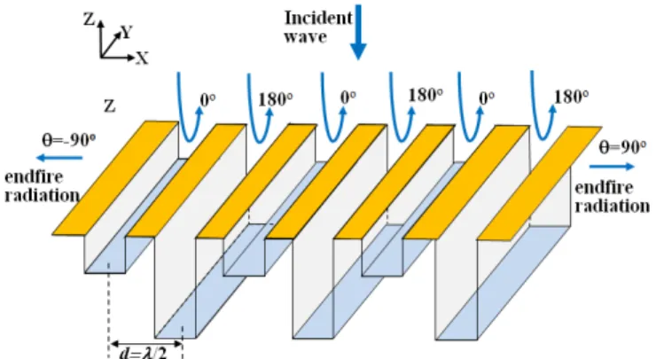
Fig.2 gives a global view of the foreseen endfire reflector based on groove unit-cells. The endfire radiation (at θ=±90°) can be achieved with out-of-phase elements and by using a half wavelength inter-element spacing as explained in [3-4] in the case of DRA elements.
B. Design of Single Groove Element
As seen from Fig. 1, the groove element possesses two degrees of freedom (width b and height h). The width b controls the part of incident wave which is transmitted into the groove. It should be large enough to guarantee that the field is not reflected back before it penetrates into the groove. All following simulations are performed using Ansoft HFSS 13.0.
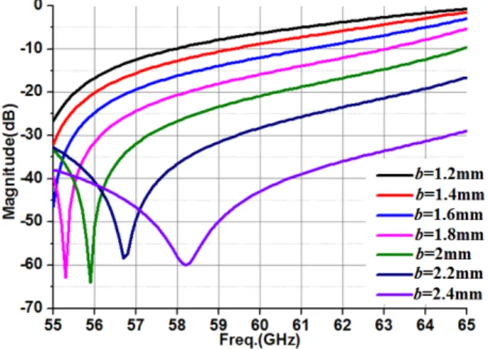
Fig. 3. S11 parameter for different b
Fig. 3 presents the reflection coefficient at the entrance of a matched groove, when b is scanned between 1.2mm and 2.4mm (2.5mm is the maximum space available for one groove along x-axis). When b=2mm, S11 at 60GHz is lower than -20dB. This value is thus selected for the following as it provides a good trade-off between efficiency and fabrication complexity. Indeed, a larger b would make the distance between two successive grooves less than 0.5mm, which would make the fabrication tricky.
For the next step, two different heights h have to be determined to produce expected out-of-phase reflection.
Fig. 4. Curve of reflection phase versus h
Fig. 4 depicts the reflected performance at 60GHz for h varying between 0 and 2.5mm. As discussed before, only two different phase-shifts with a 180° separation are required. For convenience, the successive phases are chosen as 0° and 180°. This corresponds to h1=1.19mm and
h2=2.5mm respectively, where h2 is equal to λ/2 and h1 is
quite close to λ/4. As the metallic groove element has no loss in simulations, the reflection magnitude (not shown) is almost 0dB for the whole range h. Subsequently, h1 and h2
share the same reflection magnitude which provides radiation cancellation at broadside. This configuration will now be used as a starting point for a further optimization.
It should be emphasized that, these simulations have been carried out assuming local periodicity by simulating a single groove extracted from an infinite periodic array. In the final array, two consecutive elements will be out-of-phase, which means the local periodicity assumption is not very realistic in this case. A different simulation technique could be used where two out-of-phase grooves are considered as the periodic element. Although more realistic, this configuration would be more difficult to study as it would produce no reflection for the fundamental Floquet mode (specular reflection). Then, optimization should be led involving higher order modes. In order to approximate the actual mutual coupling between consecutive elements, h1
and h2 have been re-optimized here by considering a
finite-size array, as explained in the next section.
III. ARRAY IMPLEMENTATION AND OPTIMIZATION
In this section, a preliminary 6-groove array (whose size is 15mm×15mm) is considered, as shown in Fig. 5. The 6-groove array is placed in the X-Y plane and excited by an x-polarized incident wave under normal incidence. The 180° phase-shifting is applied in the E-plane (X-Z plane) so that null radiation is expected in the z direction and maximum radiation along the x-axis.
Fig. 5. Schematic of 15mm×15mm array based on groove elements
In order to provide a more synthetic view, the parameter Ψ=
(
( )
)
( )
(
)
endfire 90 broadside 0 E E °° is used as a global figure
of merit to assess the difference between array’s radiation fields in ± 90° and 0° directions. As we seek for maximum
endfire radiation and minimum reflection at broadside, the highest Ψ is the optimization goal.
Fig. 6. 2D surface comparison of Ψ when h1=0.5-1 mm and h2=2.1-2.4mm
To reach this goal, h1 is varied in the [0.5, 1] mm range
and h2 in the [2.1, 2.4] mm range (Fig.6). The final
optimization result for the 15mm×15mm array is determined as h1=0.62mm and h2=2.28mm. For comparison,
the directivity pattern of the optimal array (Eθ in E-plane) is compared in Fig.7 with that of the initial array (i.e.
h1=1.19mm and h2=2.5mm as derived in section II).
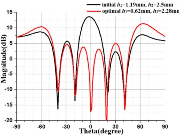
Fig. 7. Directivity comparison in E-plane (Eθ) of initial and optimized result at 60GHz.
As can be seen, the reflection at broadside has been greatly reduced while the level out of broadside has been increased. A large amount of the reflected power is now redirected longitudinally to the reflector surface, as required for a T-shaped corridor configuration. However, we can notice the maximum radiation is not obtained at endfire but at θ=-61° and 65°. This can be explained by the elementary pattern of the single groove element which decreases as θ moves to ±90°. When it is multiplied with the endfire array factor, the maximum is inevitably shifted from ±90. Note that the precise shift is dependent on the size of the reflector since it controls the array factor.
Regarding the bandwidth, simulations have shown that the level of the main beams (close to endfire) is quite stable (1-dB bandwidth) on a 9 GHz range, which is the most important output for the foreseen application. As an
illustration, Fig.8 shows the variation versus frequency of the directivity for these main beams (the magnitude is an average value of the beams at θ=-61° and 65°). On the other hand, the perfect cancellation of the parasitic reflection at broadside is very narrowband (less than 1GHz).
Fig. 8. Directivity of the main beams (average value) versus frequency
IV. ARRAY MEASUREMENT
Fig. 9. A larger 80-groove array whose size is 200mm×200mm
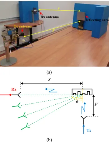
A larger array of 200mm×200mm (as shown in Fig.9) has been fabricated for measurement. As depicted in Fig.10 (a), two identical horn antennas (Tx and Rx) are placed orthogonally to simulate the NLSO environment.
The measurement is divided into two steps. At first, the reflecting array is not included, the signal is transmitted from Tx antenna, and the power received by Rx antenna at 60GHz is recorded (red curve in Fig.11) as reference. Then, the reflecting array is added and the measurement is repeated. In this second step, the position of the Rx antenna is adjusted to localize the optimal angle θ, where the maximum power can be obtained (Fig.10 (b)). When θ=75°,
S=1.5m and F=2m, the received power (black curve in
Fig.11) is compared with the initial reference from the NLOS situation.
(a)
(b)
Fig. 10. Schematic of (a) measurement settings for the reflecting array at 60GHz, and (b) top view to show how localize the optimal θ
Fig. 11. Comparison of the received power at 60 GHz between the reference and the improved one with array when θ =75°, S=1.5m and F=2m.
Fig.11 offers a clear demonstration of the array’s performance. When no array is included, the received power is close to noise floor at -85dB. When the reflecting array is utilized, the received power, now being -55dB, witnesses a significant improvement by 30dB.
V. CONCLUSION
This paper has demonstrated the capability of a planar reflector made of a ground plane with grooves to provide a quasi-endfire radiation. Design processes at the cell and array levels have been detailed showing the necessity to re-optimize the dimensions in order to account for realistic mutual coupling effects. Finally, a 200mm×200mm array has been fabricated and measured. With the help of the reflecting array, the signal towards endfire direction benefits a significant improvement, which is very helpful for the communication in the prescribed T-shaped corridor configuration.
REFERENCES
[1] T. Baykas, S. C. Sean, L. Zhou, Y. Wang, M.A. Rahman, H. Harada, S. Kato, “IEEE 802.15.3c: the first IEEE wireless standard for data rates over 1 Gb/s”, IEEE Communications Magazine, vol. 49, no.7, pp.114-121, Jul., 2011.
[2] S. Marano, W. M. Gifford, H. Wymeersch, M. Z. Win, “NLOS identification and mitigation for localization based on UWB experimental data”, IEEE Journal on Selected Areas in Communications, vol.28, pp.1026-1035, Aug., 2010.
[3] D. Wang, R. Gillard, R. Loison, “A Notched Dielectric Resonator Antenna Unit-Cell for 60GHz Passive Repeater with Endfire Radiation”, European Conference on Antennas and Propagation (EuCAP2014), pp. 3167-3170, Apr., 2014.
[4] D. Wang, R. Gillard, R. Loison, “A 60GHz passive repeater with endfire radiation using dielectric resonator antennas”, IEEE Radio and Wireless Symposium (RWS2014), pp.31-33, Jan., 2014. [5] D. M. Pozar, S. D. Targonski, H. D. Syrigos, “Design of millimeter
wave microstrip reflectarrays”, IEEE Transactions on Antennas and Propagation, vol.45, no.2, pp.287-296, Feb., 1997.
[6] J. Huang, R. J. Pogorzelski, “A Ka-band microstrip reflectarray with elements having variable rotation angles”, IEEE Transactions on Antennas and Propagation, vol.46, no.5, pp.650-656, May, 1998. [7] D. M. Pozar, T. A. Metzler, “Analysis of a reflectarray antenna using
microstrip patches of variable size”, Electronics Letters, vol.29, no.8, pp.657-658, Apr., 1993.
[8] D. G. Berry, R. G. Malech, and W. A. Kenned, “The reflectarray antenna”, IEEE Transaction on Antennas and Propagation, vol. AP-11, pp. 645-651, Nov. 1963.
[9] Y. H. Cho, S. K. Lim, S. W. Lee, M. W. Yi, W. S. Lee, and J. H. So, “A Metal-Only Reflectarray (MOR) Antenna Excited by Equivalent Surface Current Sources to Model Arbitrary Feeds”, European Conference on Antennas and Propagation (EuCAP2014), pp. 1921-1923, Apr., 2014.
[10] Y. H. Cho, W. J. Byun, M. S. Song, “Metallic-Rectangular-Grooves Based 2D Reflectarray Antenna Excited by an Open-Ended Parallel-Plate Waveguide”, IEEE Transactions on Antennas and Propagation, vol.58, no.5, pp.650-656, May, 2010.