HAL Id: hal-01852241
https://hal.archives-ouvertes.fr/hal-01852241
Submitted on 1 Aug 2018
HAL is a multi-disciplinary open access archive for the deposit and dissemination of sci-entific research documents, whether they are pub-lished or not. The documents may come from teaching and research institutions in France or abroad, or from public or private research centers.
L’archive ouverte pluridisciplinaire HAL, est destinée au dépôt et à la diffusion de documents scientifiques de niveau recherche, publiés ou non, émanant des établissements d’enseignement et de recherche français ou étrangers, des laboratoires publics ou privés.
Toward a three-dimensional finite-element model of the
human inner ear angular accelerometers sensors
Pierre Selva, Joseph Morlier, Yves Gourinat
To cite this version:
Pierre Selva, Joseph Morlier, Yves Gourinat. Toward a three-dimensional finite-element model of the human inner ear angular accelerometers sensors. International Journal for Computational Vision and Biomechanics (IJCV & B), 2010, 3 (2), pp.149-156. �hal-01852241�
Toward a three-dimensional finite-element model of the
human inner ear angular accelerometers sensors
Pierre Selva
a,*, Joseph Morlier
aand Yves Gourinat
aa
Université de Toulouse-IGM-ISAE, Toulouse, France
*Corresponding author. Tel. + 33 561 338 131; fax: + 33 561 338 330. Email-address: [email protected]
The vestibular section of the inner ear is partly comprised of three semicircular canals that detect head angular acceleration. This system is filled with a Newtonian fluid and its functioning pertains on fluid-structure interactions. The aim of the present paper is first to present a two-dimensional model of a single semicircular canal using fluid-structural finite-elements simulations. Second, this two-dimensional model is extended to 3-D space and to the case where the entire set of canals is considered. To achieve this goal, we first develop a two dimensional finite-elements model of a single canal. Using a strong coupling between the fluid flow and the structural displacements and also an Arbitrary Lagrangian Eulerian (ALE) approach for the moving mesh, we analyze displacements of the cupulae and fluid velocity during head rotation. Second, this 2-D model is extended to a three-dimensional case by considering the entire set of canals. Preliminary results showing cupula deformation as well as fluid flow highlight a good correlation with the 2-D model.
Introduction
Daily human activity includes complex orientation, postural control, and movement coordination. All these tasks depend upon his perception of motion. The non-auditory section of the human inner ear, the vestibular system, is recognized as the prime motion sensing center. It represents an inertial measuring device which allows us to sense, in the absence of external sensory cues (vision, etc) self motion with respect to the six degree of freedom in space. The vestibular system, which constitutes a very small fluid-filled system the size of a pea, is comprised of two primary sense organs: three semicircular canals which detect head angular acceleration and two otolith organs which respond to linear accelerations of the head and to gravity. In particular, when our head experience a movement of rotation, the fluid in the canal lags behind due to its inertia and produces a force across a thick diaphragm called the cupula. Therefore this diaphragm, which completely occludes the canal, experiences a deflection in the opposite direction of head movement.
The cupula covers a transverse ridge of sensory epithelium called the crista that contains thousand of sensory hair cells. When the cupula is deflected, hair cell sensory cilia bend as well. This initiates a complex transduction process in hair cells and vestibular afferent neurons, and a nervous signal is finally transmitted to the brain so as to provide a sensation of motion.
In the present paper, we are concerned with the modeling of the entire set of semicircular canals. Since the 30’s, numerous models of the semicircular canal macromechanics have been suggested using different approaches. W. Steinhausen (1933) formulated a classical torsion pendulum model for the dynamic behavior of a single SCC. This model, which has been the benchmark for subsequent works, consists of a single-degree of freedom overdamped spring-mass-damper system subject to mass-proportional inertia forcing. Several notable extensions have then been made to enhance this original model by relating the geometry and structure of the SCC to mass, stiffness, and damping parameters appearing in the model (e.g. Van Egmond et al., 1949; Groen et al., 1952; Van Buskirk, 1976; Oman et al. 1987; Rabbitt et al., 2004). Other models were based on the resolution of the fluid flow equation within the canal (Van Buskirk, 1977; Van Buskirk, 1988; Steer, 1967; Oman et al., 1987; Damiano et al., 1996; Rabbitt et al., 1999). The three-dimensional model of Oman et al. (1987), in which the non-uniform geometry of a single canal was considered, probably constitutes the most compatible biophysical single-degree of freedom model of the SCC. Among all these models, some are formulated in one dimension, while few of them consider a three-dimensional geometry. Moreover, all of these models consider a single canal and most of them do not take into account the fluid-structure interaction but rather consider the influence of the cupula by a punctual elasticity.
The aim of this paper is to model the entire set of semircircular canals by taking into account fluid-structure interactions in order to investigate fluid flow and cupula motion during head rotation. To achieve this goal, we use the finite-element Comsol Multiphysics software as it permits to deal with different physics, and more particularly with FSI problems. The modeling strategy is as follows: first, we model a two-dimensional cross-section of the lateral semicircular canal using geometry and dimensions extracted from measured human data by Curthoys and Oman (1987); second, we extend this 2D model to a three-dimensional model of a single semicircular canal; and third, we develop a fully three-dimensional model by considering the three SCCs.
2. 2D model
2.1. Geometry of the 2D model
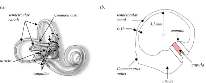
We here consider a two-dimensional cross-section of the lateral semicircular canal. The geometry and all the associated dimensions (Fig. 2.12) are extracted from measured human data by Curthoys and Oman (1987). The canal consists of three main regions: the semicircular canal, the ampulla, and the utricle. The canal is filled of a water-like fluid, known as endolymph. The model also considers the cupula (solid) located in the ampulla which completely seals the canal.
2.2. Governing equations
We now present the governing equations describing the behavior of the cupula and of the endolymph. Typically, these equations are solved for displacement and for velocity and pressure respectively. We model the endolymph as an incompressible Newtonian fluid. The typical governing equations of fluid flow are described in terms of the following two dimensional Navier-Stokes equations:
( ) f f f f f f U U U F t
ρ
∂ +ρ
⋅∇ = + ∇⋅σ
∂ (1) 0 f U ∇⋅ = (2)where ρf is the fluid density, F is the volume force affecting the fluid, σf is the Cauchy stress tensor, Uf =(uf,vf ) is the velocity field, and p is the pressure. The first equation is the momentum transport equation, and the second is the equation of continuity for incompressible fluids. These equations describe how the velocity, pressure, and density of a moving fluid are related.
The structural deformations of the cupula are solved using an elastic formulation and a nonlinear geometry formulation to allow large deformations that may occur due to its very low stiffness. Neglecting body forces, the Navier equation of motion for the cupula can be written in terms of displacement vector Us =( ,u vs s) as:
2 ² s s s U t ρ ∂ = ∇⋅σ ∂ (3)
We consider an elastic isotropic material for the cupula so that the generalized Hooke’s law is obtained:
2 ( )
s tr I
σ = µε λ ε+ (4)
where µ and λ are Lame’s coefficients, which are related to Young’s modulus of elasticity and Poisson’s ratio
ν
, by the following equations:2(1 ) E µ ν = + (5) (1 )(1 2 ) E ν λ ν ν = + − (6)
Regarding the question of exchanging information, typically in the form of boundary conditions at the interface, we adopt a two-way (or fully) coupled FSI. In this case, the response of the solid is strongly affected by the response of the fluid, and vice versa. In other words, fluid flow causes deformation of the structure. This deformation, in turn, changes the boundary conditions for the fluid flow. In addition, due to this coupling, conditions are needed to ensure that the fluid and structural domains will not detach or overlap during the motion (Fig. 2.13). For a viscous fluid, the coupling between fluid and structure requires that velocities coincide along the interface. In particular, the time derivatives of the structural displacements define the fluid’s velocity so that:
s f dU U dt = (7)
In addition, the force exerted by the fluid on the solid boundary must be considered and is the negative reaction force on the fluid given by:
(
)
(
T)
f f
f = − ⋅ − + ∇n pI η U + ∇U
(8)
where n is the outward normal vector to the boundary. This load represents a sum of pressure and viscous forces.
2.3. Boundary conditions
The aim of the model is to investigate fluid flow dynamics as well as cupula motion during head rotations. Therefore we apply a step in angular velocity to the semicircular canal. However, in order to avoid problems with discontinuity and to improve numerical reliability as well as convergence, we use smoothed Heaviside functions with a continuous second derivative that emulates the step of angular velocity.
Regarding the boundary conditions of the solid domain (cupula), we prescribe a rotational displacement at the top and bottom of the cupula and the fluid load is applied on the wetted surfaces of the cupula. As regard the fluid domain, we impose an angular velocity at the wall of the canal. Consequently the fluid in contact with the wall of the duct rotates at the same angular velocity of the canal, which is locally equivalent to a no-slip condition. We also consider an open boundary at the common crux outlet so the nodal velocities are left free to accommodate inflow and outflow of endolymph between the horizontal semicircular canal and the other canals. Finally, at the interface endolymph/cupula we apply the structural velocity of the cupula as well as the fluid load.
In order to model effectively the FSI problem we consider an Arbitrary Lagrangian-Eulerian (ALE) method which is a common application in engineering used to solve problems pertaining to structure and fluid mechanics analysis (Donea et al., 2003). The ALE method employs the use of reference frames to represent the classical Lagrangian and Eulerian systems. The Lagrangian reference frame is used to study the structure problem while the Eulerian reference is used to study the fluid problem. Hence, the model combines the fluid flow with structural mechanics by using a moving mesh to make sure the fluid flow is deformed along with the cupula.
The model is divided into different subdomains so as to specify precisely how the mesh displacement is computed (Fig. 2). The imposed conditions of mesh displacement are as follows:
• Solid domain (cupula): the displacements ( ,u vs s) provided by the computation of the
structure mechanics equations are imposed. In other words, a Lagrangian method is used where the mesh movement follows the material motion.
• Fluid domain near the cupula: as cupula deformation may affect fluid flow in its
vicinity we define two subdomains on both sides of the cupula where the mesh is free to move. This means that the mesh is constrained only by the boundary conditions on the surrounding boundaries.
• Rest of the fluid domain: the displacement of rotation imposed to the whole structure
is also applied to this subdomain. In other words, the mesh is not deformed and follows the rotation of the canal.
3. Simulations
Numerical solutions of the governing system of coupled nonlinear system partial differential equations (PDEs) are generated using finite-element analysis software (Comsol Multiphysics 3.5a) on a 2-D mesh with 2663 quadratics triangular elements that represent 16985 degrees of freedom. We consider a rotation of the structure at a constant angular velocity ofπ/ 2 rad/s around a vertical axis passing through the center of the canal (Fig. 3). Note that this consideration does not exactly mimic a head rotation as each inner ear is located approximately 3 cm away from head vertical axis. However, as stated by many researchers [], we consider that the SCCs are only stimulated by head angular accelerations and thus we do not take into account tangential as well as normal acceleration components that appear during any rotation of the head. The imposed rotation is maintained during 15 s and the computation is performed till t=30s in order to investigate fluid dynamics and cupula motion after the deceleration phase. We consider a Young’s modulus for the cupula of 5 Pa and a Poisson’s ratio of 0.48 (Selva et al., 2009).
3.1.Results at the onset of the imposed rotational motion
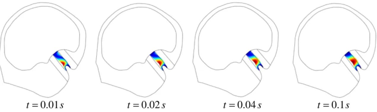
The displacement of the cupula is shown in figure 4. It can be observed that displacement begins at the base of the cupula close to the crista, which involves that initial movements of the cupula produce a shear type deformation right above the sensory epithelium. Thus, sensory hair cells are presumably stimulated as soon as head motion starts which highlights
the hypersensitivity behavior of the sensor. After a certain limit is reached, about 0.1 s, maximal displacement spreads toward the center of the cupula. This behavior is consistent with previous studies of McLaren (1977) who measured the positions of oil droplets, which were injected in the cupula of the bullfrog, following the compression of the canal wall.
Velocity profiles of the fluid flow in the slender part of the canal are plotted in figure 5. In about 0.04 s – 0.05 s the fluid flow is analogous to a Poiseuille flow. Indeed, the velocity profile tends to a parabola, with the fluid in the center of the canal having the greatest speed. This result is consistent with previous analytical studies. For instance, Groen (1952) assumed a fully developed Poiseuille flow in a straight tube to investigate the dynamics of semicircular canal flow and cupula motion, while Van Buskirk et al. (1976) shown that endolymph volume displacement resulting from a step change in angular velocity under the non-steady state flow assumption can be approximate by the Poiseuille steady-state flow relation.
3.2.Dynamic behavior of the structure during the imposed rotational motion
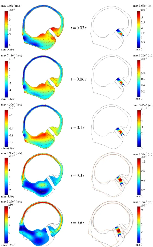
We now study the response of the sensor during both the acceleration and deceleration phase of the imposed rotational motion. Figure 6 presents the fluid flow in the canal and cupula motion at the onset of the simulation. At the beginning of the rotation of the canal, the fluid lags behind due to its inertia. Therefore, fluid flow relative to the wall of the canal is oriented in the opposite direction of the imposed rotational motion during about 0.25 s (Fig. 6). Meanwhile, this flow, represented by the arrows in figure 6, exerts a pressure across the cupula, and thus deflects it in the opposite direction of rotation as well. The deflection of the cupula reaches a maximum value close to 15 µm for the set of elastic properties retained. At time t=0.3 s, even though the canal still experiences a rotational motion, the cupula starts to return to its rest position due to its elastic properties. In addition, because of the small diameter of the duct and the viscosity of the fluid, the latter tends to catch up with the rotation of the canal, eliminating little by little the relative movement between the fluid and the canal. One can notice that the maximum fluid velocity is decreased by a factor 20 between time instants 0.3 s and 0.6 s.
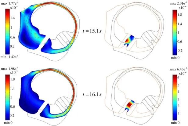
Figure 7 shows the dynamic behavior of the sensor when its rotation is suddenly stopped. The canal experiences a constant angular velocity until t=15 s, and then the movement of rotation is stopped in 0.3 s. At time t=15.1 s, the fluid is still in motion within the canal due to its inertia. As a consequence, the cupula, which was returned to its rest position, is deflected in the opposite direction than previously (Fig. 7). Once again, we can note that cupula deflection starts near the sensory epithelium and then spread toward its center. Finally, the cupula returns to its initial position which provokes a slight counter clockwise fluid flow.
Figure 8 shows the time-dependent displacement of a point located at the center of the cupula. It can be seen that the cupula experiences two deflections in opposite directions that are due to the acceleration and deceleration phase of the motion. This behavior is consistent with previous analytical models such as the classic torsion pendulum model (Steinhausen, 1933; Groen et al., 1952; Mayne, 1974). Indeed, cupula displacement is traditionally described by two times constant: a short time constant which governs the fast deflection of the cupula at the onset of the rotational motion, and a long time constant which governs the slow return of the cupula to its rest position.
4. Preliminary results of the entire 3-D model
The final goal of the work presented in this paper is to obtain a complete fluid-structural finite-element model of the entire set of semicircular canals + cupulae + utricle. Thus we extend the previous 2-D model of a single canal to three-dimensional space by taking into account all the angular sensors.
The geometry of this 3-D model has been developed with the CAD software CATIA V5. Then, using the STEP file exchange format, the model has been imported into Comsol Multiphysics in which meshing, simulations, and data processing have been performed (Fig. 9). Note that dimensions of the vertical canals have been taken identical as the horizontal canal, and that all the canals are assumed orthogonal.
Figure 9b shows the mesh of this model which is comprised of 45,408 quadratic tetrahedral elements that represent 498,112 degrees of freedom. The large number of elements is primarily due to the very small diameter of the canal cross-section (≈0.32 mm) which is one order of magnitude lower than the diameter of the circular path formed by each canal (≈3.2 mm). In addition the connections between each canals and the utricle has to be meshed finely to improve elements quality and to ensure convergence of the simulation. In the present case, simulations of the model are run on a computer having two dual-core processors, 8 Go RAM, and a 64-bit linux operating system.
Results of the simulation in response to head angular velocity are presented in figure 10. In particular, field displacement of the cupulae and fluid velocity at time t=0.1 s are plotted. At this instant, the fluid flow is in the opposite direction of the imposed clockwise rotational motion. The cupula of the lateral is thus deflected as predicted by the previous 2-D model. Note that cupula of the anterior canal also experiences a slight deflection due to the gravity field. Cupula of the posterior canal remains at its rest position as there is no fluid flow within this canal and as this cupula is almost aligned with the gravity vector.
These results are very promising as they are in good correlation with the previous 2-D model. This first 3-D model will be used to run further simulations in order to study various cases of vestibular disease – such as the Ménière’s disease which is due to an overpressure in the labyrinth – and to perform parametric analysis so as to study sensitivity effect, for instance of the mutual orientation of the canal plane.
Conclusion
The present paper deals with fluid-structural finite-elements model of the angular sensors of the human inner ear. These models were developed using the finite-element analysis software Comsol Multiphysics 3.5a. The endolymph has been modeled as an incompressible Newtonian fluid while the cupula was considered as an elastic solid. The fluid-structure interaction problem has been treated with a strong coupling between the fluid flow and structural displacements.
First, we have considered a two-dimensional model of a single canal and have investigated fluid flow as well as cupula motion during head rotation. Results of this model were in good agreement with previous analytical studies. We have shown that in about 0.04 s fluid flow in the slender part of the semicircular canal can be approximated by a Poiseuille flow. We have
also demonstrated that for a step change in angular velocity cupula displacement begins near the sensory epithelium and then spreads towards its center. Finally, displacement of the cupula through time was in good agreement with the classic torsion-pendulum model, i.e. described by two exponential terms defined by a short and long time constant respectively. Second, a three-dimensional finite-element model of the entire set of semicircular canals and cupulae has been proposed. The associated geometry has been constructed using a CAD software (CATIA V5) which has then been imported into the finite-element Comsol Multiphysics software. For a constant head rotation, promising results – in good correlation with the 2-D model previously developed - have been obtained as regard fluid flow and cupulae displacement. However further simulations for different profile of head motion need to be performed to validate this 3-D model. The main prospect of this work is to use the final 3-D model to simulate different kind of vestibular disorders such as the Ménière’s disease, which is caused by an increase in pressure and volume of the endolymph in the whole vestibular system.
Acknowledgements
The authors thank Nicolas Huc of COMSOL for tremendous support while performing the simulation study.
References
Curthoys, I.S., Oman, C.M., 1987. Dimensions of the horizontal semicircular duct, ampulla, and
utricle in the human. Acta Otolaryngol., 103, 254-261.
Damiano, E.R., Rabbitt, R.D., 1996. A singular perturbation model of fluid dynamics in the vestibular
semicircular canal and ampulla. J. Fluid Mech., 307, 333-372.
Donea, J., Huerta, A., Ponthot, J.-Ph, Rodriguez-Ferran, A., 2003. Arbitrary Lagrangian-Eulerian
Methods. www.wiley.co.uk/ecm/pdfs/Volume_1_Chapter_14.pdf.
Groen, J.J., Egmond, A.A.J. van, Jongkees, L.B.W., 1952. The function of the vestibular organ. Practica Oto-Rhino-Laryngologica, 14, 1-109.
Groen, J.J., 1956. The semicircular canal system of the organs of equilibrium. Phys. Med. Biol., 103-117.
Mayne, R., 1974. A systems concept of the vestibular organs. In: Kornhuber H, editor. Handbook of Sensory Physiology. Vestibular system. Psychophysics, Applied Apects and General Interpretations. Part 2. Verlin-New York: Springer-Verlag, 493-580.
McLaren, J.W., 1977. The configuration of movement of the semicircular canal cupula. Ph.D. thesis, University of Iowa, Iowa city, IA.
Oman, C.M., Marcus, E.N., Curthoys, I.S., 1987. The influence of semicircular canal morphology on
endolymph flow dynamics. Acta Otolaryngol., 103, 1-13.
Rabbit, R.D., 1999. Directional coding of three-dimensional movements by the vestibular semicircular
Rabbitt, R.D., Damiano, E.R., Grant, J.W., 2004. Biomechanics of the semicircular canals and otolith
organs. In: Highstein, S.M., Popper, A., Fay, R. (Eds), The Vestibular System. Springer, New York,
153-201.
Selva, P., Oman, C., Stone, H., 2009. Mechanical properties and motion of the cupula of the human
semicircular canal. Journal of vestibular research. Under submission.
Steer, R.W., 1967. The influence of angular and linear acceleration and thermal stimulation on the
human semicircular canal. S.M. Thesis, Massachusetts Institute of Technology, Cambridge.
Steinhausen, W., 1933. Uber die Beobachtung der Cupula in den bogengansampullen des Lebenden
Hechts. Pfleuger's Arch. ges. Physiol., 232, 500-512.
Van Buskirk, W.C., 1976. The fluid mechanics of the semicircular canals. J. Fluid Mech., 78, 87-98. Van Buskirk, W.C., 1977. The effect of the Utricle on Fluid Flow in the Semicircular Canal. Annals of Biomed. Eng., 5, 1-11.
Van Buskirk, W.C., 1988. The biomechanics of the semicircular canals. IEEE Engineering in Medicine and Biology Society, 10th Annual International Conference
Van Egmond, A.A.J., Groen, J.J., Jonkees, L., 1949. The mechanics of the semicircular canal. J. Physiol., 110, 1-17.
List of figures
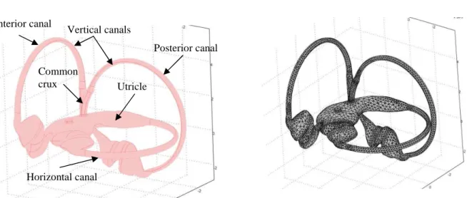
Figure 1. (a) Visualization of the inner ear and close-up sketch of the semicircular canals. (b) 2D model of the cross-section of the horizontal semicircular canal. Note that the cupula is modeled by a 400 µm thick section.
Figure 2. Visualization of the model subdomains that have different conditions for mesh displacement. A prescribed displacement is applied to the mesh of the fluid domain. The computed displacement U is applied to s
the solid domain while the mesh of the fluid subdomains on both sides of the cupula are free to move.
Figure 3. Rotational motion applied to the semicircular canal. (a) Moving mesh. (b) Profile of angular velocity applied to the structure.
xr y r O x r yr O /2rad s/
ω π
= (a) (b) t1 t0 (rad s/ )ω
2 π fluid Partitioned subdomain of fluid solid (cupula) Common crux outlet cupula utricle ampulla semicircular canal Common crux outlet semicircular canals Common crux Ampullae utricle (b) 3.2 mm 0.16 mm (a)Figure 4. Evolution of the displacement of the cupula at the very beginning of the imposed rotational motion. The displacement of the cupula begins near the sensory epithelium and then spreads towards the center of the cupula.
Figure 5. Evolution of the velocity of the fluid in the slender part of the duct at the beginning of the rotational motion. The fluid flow becomes analogous to a Poiseuille flow in about 0.05 s.
Fluid velocity along the dashed line
0.025 t= s 0.01 t= s 0.03 t= s 0.04 t= s 0.05 t= s (m /s ) 0.01 t= s t=0.02s t=0.04s t=0.1s (m)
Figure 6. Fluid velocity (left) and cupula displacement (right) at the beginning of the rotation. Visualization in the ALE reference frame (moving mesh). Due to its inertia, fluid flow relative to the canal wall is oriented in the opposite direction of the imposed rotational motion during 0.25 s. Thus, the cupula is deflected in the opposite
max 1.66e-6 (m/s) x10-6 1 0 -1 -2 -3 -4 -5 min -5.59e-6 x10⁻⁴ 2 0 -2 -4 max 7.18e-5 (m/s) min -1.42e-4 x10⁻⁴ 0.4 0 -0.4 -0.8 -1.2 4 max 4.30e-4 (m/s) min -6.29e-4 x10⁻⁴ 6 4 2 0 -2 max 7.90e-4 (m/s) min -3.49e-4 min -1.23e-5 max 3.25e-5 (m/s) x10-5 3 2 1 0 -1 3 2 1 1.5 0.5 2.5 min 0 max 3.67e-7 (m) x10-7 1 0.6 0.4 0.2 0.8 min 0 max 1.26e-6 (m) x10-6 5 3 2 1 4 min 0 max 5.65e-6 (m) x10-6 1.2 0.6 0.2 0.8 min 0 max 1.52e-5 (m) x10-5 9 3 1 7 max 9.77e-6 (m) x10-5 min 0 5 0.03 t= s 0.06 t= s 0.1 t= s 0.3 t= s 0.6 t= s
direction of rotation as well At time 0.3 s, the cupula starts to return to its rest position due to its elastic properties and the fluid flow catch up with the rotation of the canal .
Figure 7. Fluid velocity (left) and cupula displacement (right) when the rotational motion is stopped. Visualization in the ALE reference frame (moving mesh). Due to its inertia the fluid is still in motion within the canal when the latter is stopped. Thus, the cupula is deflected in the opposite direction as the first deflection experienced at the onset of the rotational motion.
Figure 8. Displacement of the center of the cupula during a constant angular rotation which ends at time t=15 s. Because of the angular acceleration the cupula is deflected according to a fast time constant (≈6 ms) and then returns to its rest position according to a long time constant (≈6 s). The inverse effect is observed when the rotational motion is stopped, i.e. when the canal experiences a deceleration.
Time (s) D is p la ce m en t (m ) min 0 max 1.98e-5 x10⁻⁵ 1.8 1.4 1 0.6 0.2 x10⁻⁴ 1.4 1 0.6 0.2 max 1.77e-4 min -1.42e-5 x10⁻⁶ 1.4 1 0.6 0.2 max 2.01e-6 min 0 1.8 x10⁻⁶ 4 3 2 1 max 6.45e-6 min 0 5 6 15.1 t= s 16.1 t= s
Figure 9. (a) Three-dimensional CAD model of the three SCCs + utricle +cupulae. (b) Mesh of the final three-dimensional model which consists of 45,408 quadratics elements representing 498,112 degrees of freedom.
Figure 10. Results provided by the simulation of the final 3D model of the semicircular canals. (a) Field of fluid velocity at time t=0.1s. (b) Field of cupulae displacement at time t=0.1 s. The cupula of the lateral canal is deflected because of the imposed motion of rotation of the canals. The cupula of the anterior canal is slightly deflected at the beginning of the simulation because of the gravitational field. Note that cupula of the posterior canal does not experience any deflection as there is no fluid flow within this canal and as this cupula is almost aligned with the gravity vector.
(b) Anterior canal Posterior canal Horizontal canal Utricle Common crux Vertical canals (a) (b) (a)