HAL Id: hal-01940634
https://hal.archives-ouvertes.fr/hal-01940634
Submitted on 17 Jul 2019
HAL is a multi-disciplinary open access
archive for the deposit and dissemination of
sci-entific research documents, whether they are
pub-lished or not. The documents may come from
teaching and research institutions in France or
abroad, or from public or private research centers.
L’archive ouverte pluridisciplinaire HAL, est
destinée au dépôt et à la diffusion de documents
scientifiques de niveau recherche, publiés ou non,
émanant des établissements d’enseignement et de
recherche français ou étrangers, des laboratoires
publics ou privés.
A New Compact and Wide-band Band-stop Filter Using
Rectangular SRR
B. Nasiri, A. Errkik, Jamal Zbitou, A. Tajmouati, L. Elabdellaoui, Mohamed
Latrach
To cite this version:
B. Nasiri, A. Errkik, Jamal Zbitou, A. Tajmouati, L. Elabdellaoui, et al.. A New Compact and
Wide-band Band-stop Filter Using Rectangular SRR. Telkomnika (Telecommunication, Computing,
Electronics and Control), Institute of Advanced Engineering and Science (IAES), 2018, 16 (1),
pp.110-117. �10.12928/telkomnika.v16i1.7578�. �hal-01940634�
DOI: 10.12928/TELKOMNIKA.v16i1.7578 110
A New Compact and Wide-band Band-stop Filter Using
Rectangular SRR
B. Nasiri*1, A. Errkik2, J. Zbitou3, A. Tajmouati4, L. El Abdellaoui5, M. Latrach6
1,2,3,4,5
LMEET, FST of Settat, Hassan 1st University, Settat, Morocco
6
Microwave Group ESEO Angers, France *Corresponding author, e-mail: [email protected]
Abstract
This paper proposes a novel compact band-stop filter based on Rectangular SRR unit cell. The BSF structure consists of modified microstrip line connected to 50 Ω feed line on both sides and Rectangular-SRR which has been added and located in the center of the proposed design. The R-SRR dimensions are chosen and optimized in order to achieve a resonant frequency in the undesired band. This filter is designed, simulated and optimized using two electromagnetic solvers. The circuit performances have been investigated and found to have an excellent BSF characterized by high power rejection level in the stop-band, low insertion loss in the both pass-bands and compact size. The experimental results illustrate that the proposed BSF achieves a wide fractional bandwidth of 72 % at 2.2GHz.
Keywords: microstrip, filter, band-stop, split ring resonator, metamaterials
Copyright © 2018 Universitas Ahmad Dahlan. All rights reserved.
1. Introduction
Suppression of unwanted range frequencies and avoidance of noise are an important issue in the microwave and wireless communication systems. This special role is performed by microstrip band-stop filters. They have been widely used in several and various wireless systems and circuits due to their ease fabrication, integration and compatibility with others planar devices. Recently, the demand for compact size, low cost and high- electrical performances BSFs is extensively increased due to the development of microwave components and all area of wireless communication. These specifications are not available by conventional and classical techniques. However, to achieve these goals several methods were explored over the years. Among them, defected ground structure (DGS), microstrip line with etched spiral resonators and metamaterials [1-12].
Metamaterials are engineered materials, their dimensions are so smaller than the wavelength of the interacting signals. They take unusual electromagnetic wave propagation properties from their structures rather than their basic compounds. In the electromagnetic field, these artificial materials are characterized by two effective constitutive parameters known as effective permittivity and permeability. These parameters describe the response of metamaterial structures to magnetic and electric fields [13-17].
The main goal of this paper is to design a new small and compact microstrip band-stop filter with high electrical performances. For these reasons, the rectangular split ring resonator is used and implemented in the structure design. To achieve desirable return loss, good insertion loss, and small size from the proposed design, various parameters were tuned and optimized using two electromagnetic solvers.
2. Rectangular Split Ring Resonator
The split ring resonators were firstly introduced by Pendry and the experimental verification of left-handed behavior was firstly achieved by Smith which used the combination of magnetic and electric resonators represented respectively by SRRs and wire medium. The first one provides the required μ-negative property and the metallic rods provide the є-negative property. Nowadays, several research works and diverse techniques have been realized to
TELKOMNIKA ISSN: 1693-6930
A New Compact and Wide-band Band-stop Filter Using Rectangular SRR (B. Nasiri) 111 achieve the resonators with negative permeability which have many useful advantages of microwave devices in term of size and electrical performances.
The SRR is basically constituted of two concentric enclosed Rings with splits in them at opposite sides. Due to the presence of the small space between the outer and inner rings, the SRR structure has a resonant wavelength larger than the diameters of these rings. This small distance and gap in the both rings produce high capacitive values that decreases the value of the resonance frequency which is given by Equation (1).
1
2
f
LC
(1) The effective medium theory is very useful to extract the material parameters from the normal scattering parameter data when analytical techniques are not easy to apply. The metamaterial characteristics of the chosen SRR unit cell are verified using Nicolson-Ross-Weir (NRW) approach. The NRW approach based on two composite terms V1 and V2 representrespectively the addition and subtraction of S-parameters given by Equation (2) and (3).
1 21 11
V
S
S
(2) 2 21 11V
S
S
(3) where the effective permeability and permittivity are related to parameters response by Equations (4) and (5). 2 0 21
2
1
effV
JK d
V
(4) 1 0 11
2
1
effV
JK d
V
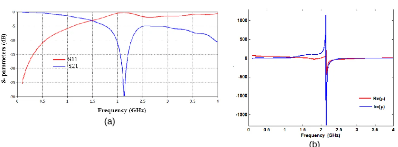
(5) where K0 presents a wave number equivalent to 2π/λ0, d is the thickness of the substrate.At first, the proposed rectangular split ring resonator is designed on an FR4 substrate and its dimensions are chosen after many series of optimization in order to achieve a resonant frequency around 2GHz. Its geometry is illustrated in Figure 1, where L= 11mm, W= 9mm, D= 1mm and g=0.5mm. Figures 2(a) and 2(b) show respectively the frequency response of the rectangular SRR and extracted real and imaginary of the permeability.
(a)
(b)
Figure 2. (a) S-parametres response of the proposed R-SRR. (b) R-SRR effective permeability versus frequency
3. Analysis and design of the proposed band-stop filter
A compact and miniaturized microstrip band-stop filter was built by using Rectangular SRR unit cell. Due to its relatively low cost, the proposed circuit is printed on Flame Resistant 4 epoxy substrate which is characterized by a relative permittivity of 4.4, a loss tangent of 0.025 and a thickness h= 1.6 mm.
The geometrical configuration parameters of the proposed BSF based on rectangular Split Ring Resonator is shown in Figure 3. It consists of two 50 Ω transmission lines connected with modified U-shaped and the proposed resonator which is added and located exactly in the center of the structure, the circuit of the optimized BSF is very simple so that the manufacturing complexity can be reduced. It has a compact size of 17x20mm2 excluding the feed lines. Where L1= 12.5mm, W1= 13mm, L2= 3mm and S=1mm.
Figure 3. Geometry of the proposed band-stop filter
To meet the requirement of the band-stop filter features in term of size and electrical performances of the rejected band and both passbands, several simulated results have been carried out and analyzed in order to choose the best one which satisfies the desired BSF filter specifications.
First of all, the proposed structure without metamaterial resonator has been simulated so as to understand the influence of the chosen rectangular SRR unit cell. It is plain to see from the Figure 4, that there is a normal transmission and no cut band is noticed in overall range frequencies extending from DC to 6GHz.
TELKOMNIKA ISSN: 1693-6930
A New Compact and Wide-band Band-stop Filter Using Rectangular SRR (B. Nasiri) 113
Figure 4. S-parametres response of the proposed filter without R-SRR
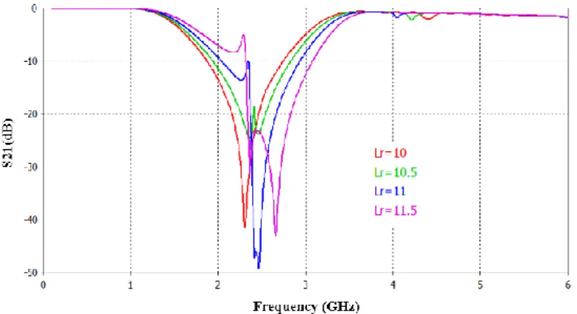
In order to achieve the BSF behavior, the rectangular split ring resonator has been implemented and all its parameters have been studied. In this investigation we just focused on the effect of two parameters. The first one is the R-SRR length which was varied from 10 mm to 11.5 mm in steps of 0.5 mm by keeping the all other parameters unchanged. Figure 5(a) and Figure 5(b) illustrate respectively the return loss and insertion loss against frequency for distinct values of the length Lr. As might be seen, it is possible to extend the bandwidth of the rejected
band and moreover the central frequency of the BSF can be shifted from 2.7 GHz to 2.4 GHz by increasing the Lr.
Figure 5. (a) Simulated return loss for different value of R-SRR length
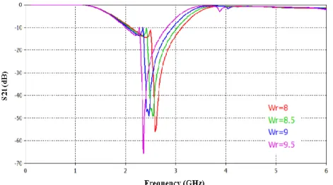
The second investigation was obtained by changing the value of the R-SRR width Wr
from 8mm to 9mm with all other parameters remains invariant. It is clearly observed from Figure 6, that as the Wr is increasing the central frequency of the rejected band is decreasing.
Furthermore, the second pass-band can be improved and its reflection-zero can be controlled and shifted by means of the R-SRR width.
Figure 6. (a) Simulated return loss for different value of R-SRR width
Figure 6. (b) Simulated insertion loss for different value of R-SRR width
The final scattering parameters of the proposed BSF are presented in Figure 7. As can be seen, the filter shows band-stop characteristic at the center frequency of 2.4 GHz and bandwidth of rejected band as 1.75 GHz [1.5GHz, 3.25GHz] with a deep rejection band of 40 dB. This filter is characterized by a stopband fractional bandwidth FBW of 70% that is given by Equation (6). 2 1 0
100%
f
f
FBW
f
(6)TELKOMNIKA ISSN: 1693-6930
A New Compact and Wide-band Band-stop Filter Using Rectangular SRR (B. Nasiri) 115
Figure 7. Frequency response of the proposed BSF by using CST Microwave studio and ADS Agilent
The current density distributions in the first pass band at 1GHz and stop band at 2.5 GHz are depicted respectively in Figure 8(a) and Figure 8(b). As we can observe in the first one, the current is stronger in the entire proposed filter which means that there is signal propagation from the input port to output port. On the other hand, from the Figure 8(b), we remark that there is a high concentration of current distribution around the port 1 and the rectangular SRR and no current near to the output port 2 which implies there is no a transmission of radio frequency power from the input port to the output port in the designed circuit. This investigation proves that our proposed filter has good electrical performances.
(a) (b)
Figure 8. (a) Simulated surface current density at the frequency 1GHz (b) Simulated surface current density at the frequency 2.5GHz
4. Fabrication and Measurement
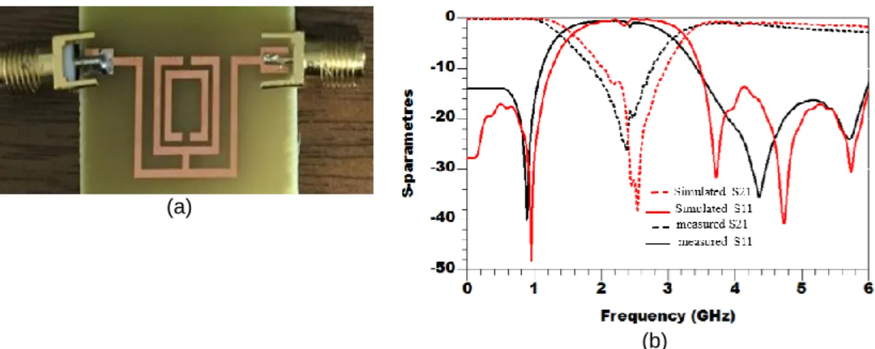
After numerous series of optimization by using two electromagnetic solvers CST Microwave and ADS Agilent. The obtained circuit has been fabricated on a 1.6 mm thick FR4 substrate by using LPKF machine. The fabricated BSF based on rectangular SRR prototype photograph is illustrated in Figure 9, It has a compact circuit size of 17x20 mm2 without 50 Ω microstrip lines, the SMA connectors were soldered to the edge of the both BSF sides.
The measurements were achieved by an R&S Vector Network Analyzer HP 8719ES. The Simulated and measured S-parameters are compared in Figure 9, It can be clearly seen that there is an excellent agreement between them.
The return loss and insertion loss indicate that the fabricated BSF with FWB= 72% and a central frequency of 2.2GHz. It provides a power rejection level can reach more than 25 dB and good return and insertion loss have achieved in both passbands. The slight deviations between the simulated and measured results are mainly caused by dielectric losses or an error in the manufacturing or measuring process.
(a)
(b)
Figure 9. (a) Photograph of The Fabricated Band-Stop Filter density at the frequency 1GHz (b) Simulated and measured S-parameters of the BSF
The fabricated band-stop filter performances are compared with other published studies in Table 1, in term of overall size, rejected band, deep rejection and stopband fractional bandwidth FBW which is used to evaluate the rejected band of a BSF. As depicted in Table 1, we can obviously observe that this filter shows remarkable electrical performances, small size and wide stop-band characterized by a good attenuation level.
Table 1. ThePerformances comparison among published BSF filters and this work
Parameters /Ref Rejected band (GHz) FBW S21 deep (dB) Size ( mm2) [3] [1.3-1.9] 37% 30 1000≥ [5] [2-3.2] 75% 30≥ 1100 [9 [10] This work [0.975-1.025] [1.3-2.3] [1.4-3] 5% 55% 72% 35 25≥ 25≥ 6370≥ 1000≥ 500 5. Conclusion
A novel compact microstrip band-stop filter based on rectangular-SRR unit cell has been proposed in this paper. The rejected band has been achieved by using metamaterial resonator which was added and implemented in the middle top layer of designed structure. It was developed and simulated using two different electromagnetic solvers and was fabricated and printed on an FR4 substrate. The proposed BSF has many desirable features such as small and compact size, wide stop-band and good electrical performances. This circuit with these characterizations will be a good choice to be implemented in modern communication systems.
Acknowledgement
We thank Mr. Mohamed Latrach Professor in ESEO, engineering institute in Angers, France, for allowing us to use all the equipment and solvers available in his laboratory
References
[1] Boutejdar A, Omar A. A miniature 5.2-GHz bandstop microstrip filter using multilayer-technique and coupled octagonal defected ground structure. Microwave and Optical Technology Letters, 2009; 51(12): 2810-2813.
[2] Pozar DM. Microwave engineering. Fourth Edition. John Wiley & Sons, Inc. 2012.
[3] Bhaskar M, Jasmi J, T. Mathew. Microstrip Bandstop Filters Based on Hexagonal Complementary Split Ring Resonators. Proceedings of Fifth International Conference on Advances in Computing and Communications (ICACC) IEEE. Kochi. 2015: 311-313.
TELKOMNIKA ISSN: 1693-6930
A New Compact and Wide-band Band-stop Filter Using Rectangular SRR (B. Nasiri) 117 [4] Esmaeili M, Bornemann J. Microstrip bandstop filters using L- and T-shaped resonators. Proceedings
of 2015 Asia-Pacific Microwave Conference IEEE. Nanjing. 2015: 1-3.
[5] Lu K, Guang MW, He XX. Compact and sharp-rejection bandstop filter using uniplanar double spiral resonant cells. Radioengineering. 2011; 20(2): 468-471.
[6] Chen W, Zhao Y, Junof Z. Compact and Wide Upper-Stopband Triple-Mode Broadband Microstrip BPF. TELKOMNIKA (Telecommunication Computing Electronics and Control). 2012; 10(2): 353-358. [7] Boutejdar A. A new approach to design compact tunable BPF starting from simple LPF topology using a single T-DGS-resonator and ceramic capacitors. Microwave and Optical Technology Letters. 2016; 58(5): 1142-1148.
[8] Nasiri B, Errkik A, Zbitou J, Tajmouati A, E Abdellaoui L, Latrach M. A New Compact Microstrip Band-stop Filter by Using Square Split Ring Resonator. International Journal of Microwave and Optical Technology. 2017; 12(5): 360-366.
[9] Carver J, Reignault V, Gadot F. Engineering of the metamaterial-based cut-band filter. Applied
Physics A. 2014; 117(2): 513–516.
[10] Yechou L, Tribak A, Mohamed K, Zbitou J, Bouyahyaoui A, Sanchez AM. Planar wideband band-stop filter with T-inverted shaped open stubs for wideband applications. International Journal of Microwave and Wireless Technologies. 2017; 9(2): 773-780.
[11] Morabito AF, Laganà AR, Sorbello G, Isernia T. Mask-constrained power synthesis of maximally sparse linear arrays through a compressive-sensing-driven strategy. Journal of Electromagnetic Waves and Applications. 2015; 29(10): 1384-1396.
[12] Morabito AF, Laganà AR, Isernia T. Isophoric array antennas with a low number of control points: a 'size tapered' solution. Progress in Electromagnetics Research Letters. 2013; 36: 121-131.
[13] Ennajih A, Zbitou J, M. Latrach, A Errkik, LE Abdellaoui, A. Tajmouati. Dual Band Metamaterial Printed Antenna Based on CSRR For RFID Applications. International Journal of Microwave and Optical Technology Technologies. 2017; 12(2): 106-113.
[14] Martin F, Falcone F, Bonache J , Marques R, Sorolla M. Miniaturized coplanar waveguide stop band filters based on multiple tuned split ring resonators. International Journal of Microwave and Optical Technology. IEEE Microwave and Wirelesss Components Letters Technologies. 2003; 13(12): 511-513.
[15] Pendry JB, Holden AJ, Robbins DJ, Stewart WJ. Magnetism from conductors and enhanced nonlinear phenomena. IEEE Transactions on Microwave Theory and Techniques. 1999; 47(11): 2075-2084.
[16] Pendry JB, Holden AJ, Stewart WJ, Young II. Extremely Low Frequency Plasmons in Metallic Mesostructures. Physical Review Letters. 1996; 76(25): 4773-4776.
[17] Veselago VG. The electrodynamics of substances with simultaneously negative values of ε and μ. Soviet Physics Uspekhi. 1968; 10(04): 509-514.