HAL Id: hal-01894312
https://hal.archives-ouvertes.fr/hal-01894312
Submitted on 12 Oct 2018
HAL is a multi-disciplinary open access
archive for the deposit and dissemination of
sci-entific research documents, whether they are
pub-lished or not. The documents may come from
teaching and research institutions in France or
abroad, or from public or private research centers.
L’archive ouverte pluridisciplinaire HAL, est
destinée au dépôt et à la diffusion de documents
scientifiques de niveau recherche, publiés ou non,
émanant des établissements d’enseignement et de
recherche français ou étrangers, des laboratoires
publics ou privés.
Spatial Scanner Channel Sounder for Space Diversity
Studies
Mamadou Dialounké Baldé, Stéphane Avrillon, Christian Brousseau,
Dominique Lemur, Bernard Uguen
To cite this version:
Mamadou Dialounké Baldé, Stéphane Avrillon, Christian Brousseau, Dominique Lemur, Bernard
Uguen. Spatial Scanner Channel Sounder for Space Diversity Studies. EuCAP2016 - European
Con-ference on Antennas and Propagation, Apr 2016, Davos, Switzerland. �hal-01894312�
Spatial Scanner Channel Sounder for Space
Diversity Studies
Mamadou Dialounk´e Bald´e, St´ephane Avrillon, Christian Brousseau, Dominique Lemur, Bernard Uguen
IETR UMR CNRS 6164, University of Rennes 1, Rennes, France
Emails : {mamadou.balde, stephane.avrillon, christian.brousseau, dominique.lemur, bernard.uguen}@univ-rennes1.fr
Abstract—This paper presents a versatile spatial scanner Vector Network Analyser (VNA) channel sounder for indoor and outdoor scenarios exploiting a four axis positioner and optical transposition devices which allow a large separation between Tx and Rx antennas. This channel sounder can be used over several frequency bands of interest for the development of future multi antenna systems. This channel sounder alllows to acquire a large number of static channel matrices through a properly sampled region of space in order to retrieve the time-varying behaviour of the MIMO channel. A measurement run of a 4x8 MIMO channel acquired along a 0.7m translation are presented to illustrate the capabilities of the sounder.
I. INTRODUCTION
Multi Users MIMO (MU-MIMO) as well as Massive MIMO have risen in discussions since the beginning of the decade. Indeed the knowledge of the MIMO channels is becoming tremendously important in the context of 5G cellular network where the full potential of this twenty years old technique [1] is going to be exploited efficiently. [2] has reviewed the necessity to characterize and model the channel radio propagation and [3] introduced the Massive MIMO concept where key benefits of this technology are explored and how it becomes a serious candidate for future wireless technology like 5G and beyond. From there, understanding the time evolution of the spectral structure of the matrix MIMO H, spatial focusing, human mobility effects become important. The VNA channel sounder exploits a four axis positioner, three translations and one rotation. Optical transposition devices allow a large separation between Tx and Rx antennas in order to extend the range involved in scenario of interest as small cells scenarios. This spatial channel sounder will allow answering questions regarding large MIMO and MU-MIMO channel matrix structure.
Here, we present a spatial scanner channel sounder and a set of LOS measurement data acquired in a small room. Section II presents the motivation of the work, section III describes the channel sounder and the measurement setup and finally we present a 4 × 8 MIMO measurement datas obtained from this spatial channel sounder.
II. MOTIVATION
Our motivation lies on the willingness to characterize the channel propagation regarding spatial focusing, variability of the channel, and power delay, elevation and azimuthal spread across a large region of space. Several recent works have
TABLE I
PARAMETERS OF THE WHOLE CHANNEL SOUNDER
Parameters Characteristics
Tx ULA 8 folded dipoles antennas
Rx ULA 4 folded dipoles antennas
VNA E5072A(up to 8.5GHz) [1.8-2.2 GHz] Scanner 4 axes (X, Y, Z, R) Polarization V Switch 1 − 4 100 ns Switch 1 − 8 50 ns RF/opt&opt/RF 100m (up to 28GHz)
shown the interest of exploiting a large scale antennas in order to investigate the impact in the channel propagation. [4], [6] investigates massive MIMO channel propagation for the lower and upper bands at 6 GHz through a measurement campaign. The purpose of this work is to study from measurement investigation, the evolution of the spectral structure of large MIMO matrices.
III. DESCRIPTION OF THECHANNELSOUNDER AND
MEASUREMENTSETUP
Table I provides the current main characteristics and Fig. 1 and Fig. 2 illustrate respectively the synoptic and picture of the presented spatial scanner channel sounder.
The transmitting array is an Uniform Linear Array (ULA) of 8 antennas matched between 1.8 and 2.2 GHz and separated by the half wavelength of d = 7.5cm corresponding to the 2 GHz centre frequency. Each antenna element consists of a folded dipole designed in vertical polarization. This antenna configuration could evolve easily for addressing higher band scenarios until the upper 28GHz limitation brought by the RF optical transposition.
An Agilent E5072A VNA is used to measure the complex S21parameter. Despite the longer time measurement, the VNA
solution offers a wideband characterization in addition to a high measurement dynamics.
As aforementioned, one of the drawback of the VNA is the centralization of the emission and reception which makes very difficult large antenna separations. To overcome this problem, optical transpositions which consists of two modules, optical to RF and RF to optical converters are used. Those devices can work up to 28 GHz and then make possible separation between receiver and transmitter antennas of up the length of the optic fibre, typically about 100m in our case.
Fig. 1. Configuration set up of the spatial scanner channel sounder
The spatial scanner is a four axis positioner. Axis are denoted X, Y, Z, R and each of them is equipped of a stepper motor connected to the stepper drives via cables of 10m length and has a sub-millimetre precision on the movements. Axis X is composed of one rail belt transmission and another rail without training for 1.62m of length. With 0.78m of length, axis Y has one rail ball screw transmission. Beside there are a axis Z which has a ball screw transmission that can stretch up to 0.4m and a axis R allows rotation over 360◦. Because we are using a VNA, the time variability of the channel should be emulated from large collections of spatial channel data. The VNA, 4 axis scanner and switches are fully controlled on a single Linux control platform. The associated Python open source code is available on the github repository [5] of the PyLayers platform [7].
For the purpose of measuring the static radio channel, it is imperative that the scanner remains static during the VNA data acquisition. This implies a handshaking protocol between the VNA and the scanner which is facilitated by having a fully centralized control over all devices. The full Python interface handling control between VNA and scanner, stores and processes data. Data are stored in numpy multidimensional array which offers a powerful data container for further MIMO post-processing. Calibration data are stored jointly with measurement data in hdf5 file format.
A. Measurement Setup
The 8 antennas of the transmiting array were connected to one of the port of the VNA via a 1 − 8 switch. The second port of the VNA was connected through optical transposition (RF-Optic) to a 1 − 4 switch, connected itself to a 4 antennas receiving array. This receiving antenna array was placed on the scanner mast (see Figure 2). The presented results are obtained from a translation ∆x = 0.7m of this array along
the radio-electric axis denoted x for 100 positions separated by 7mm. The measurement time which include switching time and data transfer time for getting the 32 sub-channels of the 4 × 8 channel matrix for one position is about 16s. The measurements were held inside a 6m × 12m room where the receiver is placed at 5.05m from the transmitter in perfect LOS situation. Several wood furnitures (tables and chairs) were present inside the room.
Fig. 2. The full equipment placed in the room of LOS experiments
Evolution of the mean and the standard deviation of H(f)
A m pl itu de (l in ea r s ca le ∈ [0 , 1] ) 1.8 2.0 2.2 0.000 0.005 0.010 0.015 0.020 0.025 0.030 Frequency (GHz)
Fig. 3. Mean (red) and standard deviation (black) of the 4x8 channel matrix Hij(f ) along the ∆x= 0.7m translation
IV. MEASUREMENTSRESULTS
This section presents a short analysis of the measurement dataset corresponding to the previously described measure-ment setup (70cm translation of the receiving antenna array in LOS indoor). To figure out the nature of the measured data, the representation of the full dataset is presented in fig 3. It represents for each sub-channel Hij(f ) in a 4 × 8 subplot
the mean value of the module of the transfer function and the corresponding standard deviation from the data measured over the whole translation.
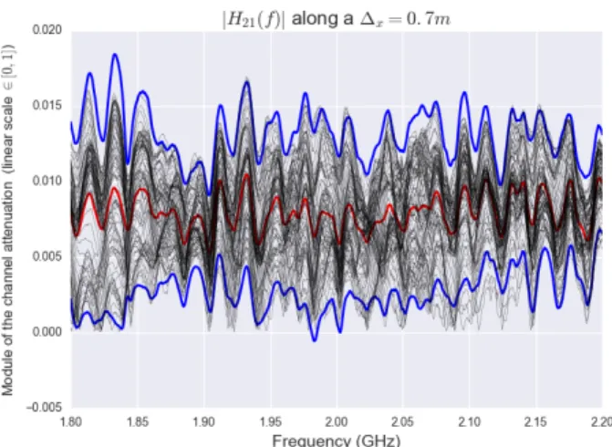
Figure 4 illustrates the 100 realizations for the isolated sub-channel H21(f ) (second line and first column of Figure 3)
superposed with the mean (red curve) and typical deviation (blue curve). This provides information over the magnitude of the observed channel variation which could be exploited for further MIMO channel matrix modelling.
The rank of the MIMO channel matrix is full (rank(H) = Nr= 4) and the large value of the first singular value reflects
Fig. 4. Module of the sub-channel H21(f ), µ|H21(f )| (red), µ|H21(f )|± 1.96σ|H21(f )|(blue), 100 realizations of |H21(f )| (black)
Fig. 5. Evolution of the 4 singular values of Hij(f ) w.r.t frequency (100 spatial realizations along 0.7m translation)
the LOS situation. Figure 5 presents the evolution of the 4 singular values associated with the MIMO channel for the whole dataset. The 100 realizations of the MIMO channel matrix are surimposed with their mean and typical deviation. We can observe that the variance of each eigenvalue w.r.t fre-quency is very different depending on the considered singular value. The first singular value exhibits a large variation in the upper part of the band whereas for the other singular values the variance is more homogeneously spread over the frequency band. Figure 6 presents the evolution of the 4 singular values of the H matrix, but this time with respect to range. The observed variability corresponds to the whole set of 801 frequency points. Interestingly the frequency variability of a given singular value is proportional to the magnitude of the singular value. For both Figures 5 and 6 the standard deviation of each singular value λihas been calculated and displayed as
an interval proportional to 3.92σλi centered around the mean.
Fig. 6. Evolution of the 4 singular values of Hij(f ) w.r.t distance (801 frequency point realizations)
V. CONCLUSIONS
In this paper, a spatial scanner VNA based channel sounder for indoor and outdoor exploiting a four axis positioner and optical transposition has been presented. Two 8 and 4 uniform antenna arrays matched between 1.8 and 2.2GHz have been used respectively on transmit and receiver side. In addition, a 4x8 MIMO channel measurement datas has been presented and demonstrates the full equipemnt capabilities. In particular the evolution of the spectral properties of the channel matrix can be investigated when the channel is modified by a a given motion. Further work will investigate this spectral structure of the channel matrix for different environemnts, frequency bands and structure of spatial grid scanning.
ACKNOWLEDGMENT
The authors would like to thank Christopher Guitton and Jean Christophe Lecun of the prototypage team of IETR for participating in the deployment of the scanner.
REFERENCES
[1] I. Emre Telatar. Capacity of multi-antenna Gaussian channels. European Transactions on Telecommunications, 10:585–595, 1999.
[2] N. Czink, A. P. G. Ariza, K. Haneda, M. Jacob, J. Karedal, J. Medbo, J. Poutanen, J. Salmi, G. Steinbock, and K. Witrisal. Channel measure-ments. In Pervasive Mobile and Ambient Wireless Communications, pages 5–65, 2012.
[3] T.L. Marzetta. Noncooperative cellular wireless with unlimited numbers of base station antennas. Wireless Communications, IEEE Transactions on, 9(11):3590–3600, November 2010.
[4] Xiang Gao, O. Edfors, F. Rusek, and F. Tufvesson. Massive mimo
performance evaluation based on measured propagation data. Wireless Communications, IEEE Transactions on, 14(7):3899–3911, July 2015. [5] https://github.com/pylayers/pylayers/tree/master/pylayers/measures [6] J. Medbo, K. Borner, K. Haneda, V. Hovinen, T. Imai, J. Jarvelainen,
T. Jamsa, A. Karttunen, K. Kusume, J. Kyrolainen, P. Kyosti, J. Meinila, V. Nurmela, L. Raschkowski, A. Roivainen, and J. Ylitalo. Channel modelling for the fifth generation mobile communications. In Antennas and Propagation (EuCAP), 2014 8th European Conference on, pages 219–223, April 2014.
[7] N. Amiot, M. Laaraiedh, and B. Uguen. Pylayers: An open source
dynamic simulator for indoor propagation and localization. In Communi-cations Workshops (ICC), 2013 IEEE International Conference on, pages 84–88, June 2013.