HAL Id: inria-00545955
https://hal.inria.fr/inria-00545955v5
Submitted on 7 Apr 2011
HAL is a multi-disciplinary open access
archive for the deposit and dissemination of
sci-entific research documents, whether they are
pub-lished or not. The documents may come from
teaching and research institutions in France or
abroad, or from public or private research centers.
L’archive ouverte pluridisciplinaire HAL, est
destinée au dépôt et à la diffusion de documents
scientifiques de niveau recherche, publiés ou non,
émanant des établissements d’enseignement et de
recherche français ou étrangers, des laboratoires
publics ou privés.
Real-Time Rough Refraction
Charles de Rousiers, Adrien Bousseau, Kartic Subr, Nicolas Holzschuch, Ravi
Ramamoorthi
To cite this version:
Charles de Rousiers, Adrien Bousseau, Kartic Subr, Nicolas Holzschuch, Ravi Ramamoorthi.
Real-Time Rough Refraction. ACM Siggraph Symposium on Interactive 3D Graphics and Games (I3D),
Feb 2011, San Francisco, United States. pp.111-118, �10.1145/1944745.1944764�. �inria-00545955v5�
Real-Time Rough Refraction
Charles de Rousiers1,3 Adrien Bousseau2,3 Kartic Subr1 Nicolas Holzschuch1 Ravi Ramamoorthi3 1INRIA Rhone-Alpes / LJK 2INRIA Sophia-Antipolis 3University of California, Berkeley
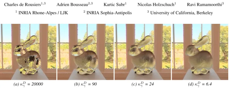
(a)κD
γ = 20000 (b)κDγ = 90 (c)κDγ = 24 (d)κDγ = 6.4
Figure 1: The Bunny model rendered with a transparent material taking into account the scattering from rough surfaces, at the entering and exiting interfaces. The technique uses a new spherical Gaussian approximation of the BTDF allowing usage of pre-convolved environment map. The effects of complex geometry at the exting interface are approximated using a normal distribution function. These images are all rendered for increasing roughness in real-time[∼ 140Hz].
Abstract
We present an algorithm to render objects of transparent mate-rials with rough surfacesin real-time, under distant illumination. Rough surfaces cause wide scattering as light enters and exits ob-jects, which significantly complicates the rendering of such mate-rials. We present two contributions to approximate the successive scattering events at interfaces, due to rough refraction : First, an ap-proximation of the Bidirectional Transmittance Distribution Func-tion (BTDF), using spherical Gaussians, suitable for real-time es-timation of environment lighting using pre-convolution; second, a combination of cone tracing and macro-geometry filtering to effi-ciently integrate the scattered rays at the exiting interface of the object. We demonstrate the quality of our approximation by com-parison against stochastic raytracing.
1
Introduction
We introduce a real-time algorithm to render translucency due to rough surfaces, such as frosted and misted glass. Translucent ap-pearance can be attributed to a combination of two factors: surface scattering, for example in frosted glass due to its surface roughness, or volume scattering in participating media. In this paper we focus on the former and assume that the media are non-scattering. In the remainder of this paper we refer to such materials as being rough refractive.
In contrast to transparent materials with specular surface,handled by existing methods [Wyman 2005; Oliveira and Brauwers 2007], transparent materials with rough surfaces present the unique chal-lenge that light is scattered in multiple directions as it enters and exits the object. The first consequence of these scattering events is
that a light ray that enters at a single point of the surface will exit over an area that depends on the scattering properties of the ma-terial and the geometry of the object. The second consequence of light scattering in rough translucent objects is that the lighting com-putation involves the integration of light over multiple directions. Our approach overcomes these difficulties by first observing that the scattering function used in previous work on rendering of rough transparent materials [Walter et al. 2007] can be well approximated by a spherical Gaussian. This allows us to replace the stochastic integration of lighting by a pre-integration, in the spirit of exist-ing work on pre-convolution of environment lightexist-ing for real-time glossy reflections [Kautz et al. 2000; Ramamoorthi and Hanrahan 2002].
Our second contribution is a combination of cone tracing [Ama-natides 1984] with geometry filtering [Han et al. 2007] to approxi-mate the exiting rays, through a homogeneous approxi-material, due to scat-tering of a single incident ray. We approximate the geometry at the exiting area as the aggregate of the normals of the exiting surface intersected by the bounding cone of the refracted rays. We then convolve the resulting normal distribution function (NDF) with the material BTDF (Bidirectional Transmittance Distribution Function) to obtain a new scattering function that we use to query the pre-convolved environment lighting.
To summarize, our paper makes the following contributions: • we describe a method to render, in real time, rough refractive objects under all-frequency distant illumination (see Fig. 1). • we introduce a new spherical Gaussian approximation of a micro-facet BTDF to extend pre-convolution based methods to refractive materials.
• we propose an innovative formulation for approximating sequen-tial refractions as convolutions involving the BTDF and the NDF at the exiting surface.
2
Related work
We review work on real time rendering of both reflection and re-fraction as well as related work in off-line rendering of rere-fraction at rough surfaces.
x Point ωx Normalized direction ~ ωx Un-normalized direction ωo Outgoing direction ωi Incoming direction n Normal
ωhr Reflected half vector
ωht Transmitted half vector
ηi Index of refraction of the incident media ηo Index of refraction of the refracting media
fr BRDF (Bidirectional Reflectance Distribution Function) ft BTDF (Bidirectional Transmittance Distribution Function) p Intersection point on the first interface
s Intersection point on the second interface S Surface of integration on the second interface D NDF(Normal Distribution Function) F Fresnel function
G Geometric function for microfacet Ω+ Upper hemisphere
Ω− Lower hemisphere L(ωo) Outgoing radiance L(ωi) Incoming radiance
· Dot product
χ+(a) Sign function (1 if a ≥ 0 and 0 if a < 0) Table 1: Notations used in this paper.
Real-time reflection of distant illumination: In the case of glossy reflections, Kautz et al. [2000] and Ramamoorthi and Han-rahan [2002] have shown that for radially symmetric BRDFs, the contribution of distant incident illumination can be pre-integrated by means of a convolution of the environment map with the BRDFs. We extend these pre-convolution based methods for transparent ma-terials with non-specular BTDFs.
Real-time refractions: Most existing work on real-time refrac-tions focus on the special case of specular BTDFs, for which a single light ray travels through the object at each pixel [Wyman 2005; Oliveira and Brauwers 2007]. Recent methods on specular refractions handle complex light transport scenarios in real time, including non-homogeneous media and caustics [Sun et al. 2008; Ihrke et al. 2007; Cao et al. 2010]. While Heidrich et al. [1999] and Eisemann and D´ecoret [2006] address the rendering of rough refraction in real-time using pre-convolved environment maps, they approximate light transport inside the object with a single light ray. In contrast, our method relies on cone-tracing [Amanatides 1984] to efficiently account for multiple refracted rays inside the object. BTDF models : Just as microfacet BRDFs model glossy reflec-tions, a microfacet BTDF for rough refractions has been derived by Walter et al. [2007]. This model is expressed as (notation is shown in Table 1): ft(ωht, n) = |ωi· ωht||ωo· ωht| |ωi· n||ωo· n| (1) η2 o(1 − F (ωo, n))D(ωht, n)G(ωo, ωi, ωht) (ηi(ωi· ωht) + ηo(ωo· ωht))2
where ηi and ηo are the indices of refraction (IOR) of the inci-dent and refracting media respectively, D is the normal distribution function (NDF) and G is the geometric term that models effects such as masking and shadowing. Several choices are possible for the NDF D, such as the Beckmann and GGX [Walter et al. 2007] distribution. We use the Blinn-Phong model for its simplicity. The Blinn-Phong NDF is parametrized with κDγ, the inverse roughness
Ω pt θi θt αt r ft Ω Ω+ Ω -ωo n f p ω np np o ωo p p p r f t f + -(a) (b) (c) η o ηi η o ηi
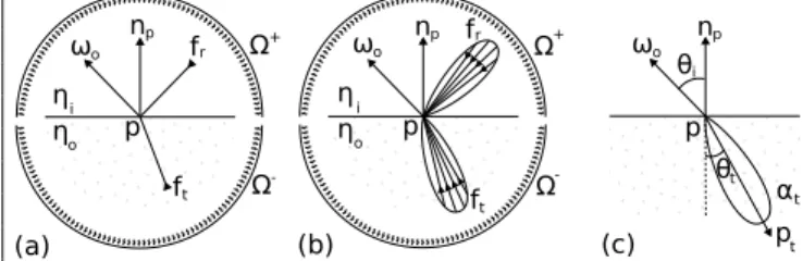
Figure 2: BSDF and notation. (a) A specular BRDF fr and a specular BTDFft, (b) A glossy BRDFfr and a rough BTDFft, (c) Spherical Gaussian parametrization used for approximating the lobe of the refractive microfacet model.
(high values of κDγ yield sharp refractions) :
D(ωht, n) = χ + (n · ωht) κDγ + 2 2π (n · ωht) κDγ (2) This microfacet BTDF model is expressed according to the refrac-tive half vector ωht, equivalent of the half vector for reflective
mod-els ωhr[Blinn 1977]. The refractive half vector is defined as :
ωht= ~ ωht || ~ωht|| = − ηoωo+ ηiωi ||ηoωo+ ηiωi|| (3) When ωhtand the surface’s normal n are collinear, ωiand ωo
fol-low Snell’s law:
ηi sin θi= ηosin θo (4)
Dai et al. [2009] propose a similar model for the particular case of thin surfaces, for which light transport in the object can be omitted. While these microfacet models can easily be integrated in a ray-tracer, the large number of samples required to handle rough mate-rials is prohibitive for real-time applications. In this paper we iden-tify that Walter’s BTDF model is well approximated by a spherical Gaussian function, which allows us to pre-convolve environment maps for real-time rendering.
3
Theory
The exiting radiance L(p, ωo) at a point p on the surface of a trans-parent material, along the direction ωo, is the integral of the incom-ing radiance weighted by the reflectance function. For clarity, we separate the full scattering function into a BRDF (fr), expressing scattering effects over the upper hemisphere (Ω+), and a BTDF (ft), expressing scattering effects over the lower hemisphere (Ω−). Both hemispheres, Ω+and Ω−are defined with respect to the tan-gent plane at p. L(p, ωo) = Z Ω+ L(p, ωi) fr(ωo, ωi) dωi + Z Ω− L(p, ωi) ft(ωi, ωo) dωi (5)
For specular refraction, the BTDF ft is simply a Dirac along the direction given by Snell’s law of refraction (see Figure 2a). For rough surfaces, the micro-geometry around point p defines the dis-tribution ft(see Figure 2b).
Under our two-interface assumption, the exiting radiance at p is the result of successive scattering processes at two boundaries (see Fig-ure 3). That is, ignoring the BRDF in Equation 5 and accounting
n Ωp p s ωo p ωo np np ωo p p _ Ωp_ Ωp _ ns Ωs _ ns ωi ω s ωq sp ωsp s (a) (b) (c)
Figure 3: Refraction at two interfaces. (a) Integration of the BTDF at the first interface. (b) Stochastic integration of incident direc-tions over the BTDF lobe atp. (c) For each sampled direction in (b), integration over the BTDF lobe ats along which radiance is queried from the environment map.
for refraction at only two interfaces — entry and exit — on a ho-mogeneous glossy object, the outgoing radiance at an entry point p can be expressed as an integral over the exiting surface S
L(p, ωo) = Z
S
L(p, ωsp) ft(ωsp, ωo) J (np, ns, p, s) ds (6)
where ωsp= ~sp/|| ~sp||, npand nsare normals at p and s respec-tively, J (np, ns, p, s) is the Jacobian associated with the change of variables from solid angle to the surface S and
L(p, ωsp) = Z
Ω+s
L(s, ωq) ft(ωq, ωps) dωq. (7)
3.1 Refraction using convolution
The primary challenge in real-time rendering of reflections and re-fractions for rough surfaces is rapid evaluation of the integral over Ω+and Ω−, which corresponds to a convolution of the incident il-lumination with a BSDF [Ramamoorthi and Hanrahan 2001]. As-suming distant lighting, and ignoring visibility, existing methods for real-time rendering of glossy reflections pre-compute the inte-gral over Ω+by convolving the environment map with the BRDF fr. This pre-convolution is independant of incident direction for radially symmetric BRDFs and the integral is evaluated at run time with a single look-up in the environment map in the direction of specular reflection.
We extend this pre-convolution approach to the case of refraction and pre-compute the integral over Ω−as a convolution of an envi-ronment map with the BTDF ft. However, the pre-convolution ap-proach requires a radially symmetric representation of the BTDF, which is not the case for the BTDF model of Walter et al. [2007]. We observe however that the BTDF response for a given incident angle and index of refraction is radially symmetric and can be well approximated by a spherical Gaussian, as illustrated in Figure 4. We express this spherical Gaussian representation of the BTDF as: ft(ωo, ωi) = αteκt(pt·ωi−1) (8) where αtis a scaling factor controlling the amplitude of the Gaus-sian lobe, κtis an exponent controlling the width of the lobe, and pt is the principal direction of the lobe (see Figure 2). These parame-ters are fitted for each incident angle θi, each index of refraction η and each BTDF exponent κDγ :
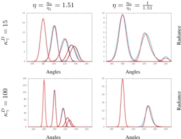
T (θo, η, κDγ) → (αt, κt, pt) (9) η = ηo ηi = 1.51 η = ηo ηi = 1 1.51 κ D γ = 15 Radiance Angles Angles κ D γ = 100 Radiance Angles Angles
Figure 4: Comparison between the actual BTDF model (red) and our Gaussian approximation (blue) for different incident angles (0,30,60,80 and 88 degrees), for two different values of roughness κDγ. We show both values for light entering the material (η = 1.51) and for light leaving the material (η = 1
1.51). At the exiting in-terface, total internal reflection can happen, resulting in a smaller number of curves. n γ ωo ωi ωo ωo p p p i ωi q ω (a) (b) (c) p np np γ n S ω
Figure 5: Approximated transport. (a) Transport from the first to the second interface with the actual geometry. (b) The geometry on the second interface is replaced by a single lobe NDF (mean + variance) (c) A new BTDF is derived from the NDF to include the local geometry.
For a given index of refraction η, we precompute the functions cor-responding to the two interfaces: T (θo, η, κDγ) and T (θo, 1/η, κDγ) and store them in 2D textures indexed by θiand κDγ.
3.2 Light transport as geometry filtering
We now focus on light transport inside the object. As described by Equation 6 and Figure 3, light enters the transparent object at the first interface, is scattered by the BTDF and transported through the object, before finally exting at the second interface, where it is again scattered by the BTDF. Our goal is to find a good approximation of equation 6 for achieving real-time performance.
Our key idea is to replace the transport problem with a filtering problem (Figure 5): we extend the work of [Han et al. 2007] and represent the geometry intersected by the scattered rays at the sec-ond interface as a flat proxy enriched with a Normal Distribution Function (NDF). We then convolve this NDF with the BTDF to ob-tain a new BTDF that models the effect of both the transmittance function and the aggregated exiting geometry.
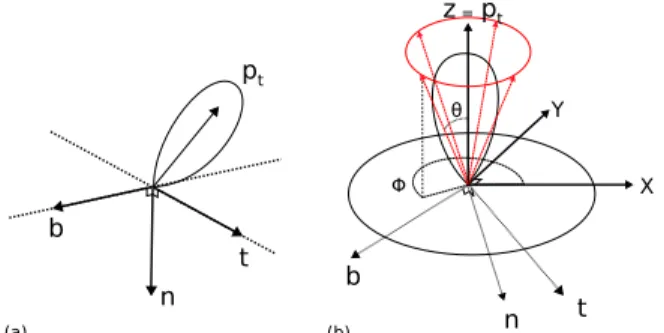
(a) pt n θ = Φ (b) z pt X Y n t b t b
Figure 6: Lobe bounding : (a) Tangent frame in which the BTDF is expressed. (b) A tangent frame is built around the main axis of the BTDF, and 4 rays generated in spherical coordinates by using the bounding angleθbcomputed by equation 12.
This approach is valid under three assumptions: (1) that all rays are parallel as they reach the exiting interface; (2) that the shape of the BTDF lobe is independent of the incident angle; and (3) that a single lobe NDF will be sufficient to represent the under-lying geometry. While refraction is an important phenomenon, hu-mans have difficulty perceiving or assessing the accuracy of results. Consequently, our model leads to plausible results with real-time frame rates despite the above assumptions. Our results, in Section 5, demonstrates the efficacy of our model.
To compute the parameters of the resulting BTDF, we convolve the NDF of the geometry γ (with an exponent κGγ) with the original NDF of the BTDF, D (with an exponent κD
γ). The result is a new NDF, D0, whose exponent κDγ0 is defined as:
κDγ0 = κG γ κDγ κG γ + κDγ (10)
As shown in Figure 5c, we orient the proxy surface perpendicular to the average normal nγ, and use it to refract the direction of the central lobe ptof the first interface using the new BTDF.
4
Algorithm
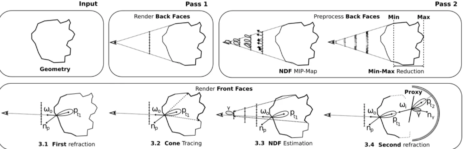
Figure 7 describes the main steps of our algorithm, that we imple-ment using three rendering passes. The first two passes compute geometric information about the scene, such as the NDF at the sec-ond interface at multiple scales and the range of depth covered by the back faces of the mesh. The third pass uses this information to approximate the transport of refracted rays inside the object with cone tracing. We finally convolve the NDF of the intersected ge-ometry at the second interface with the BTDF and evaluate the illu-mination by a lookup in the pre-convolved environment map by the resulting distribution.
We describe here the pre-computation and the three rendering passes of our algorithm in more detail.
4.1 Pre-computation
Gaussian BTDF : We pre-compute the parameters θt, αt,κt of the Gaussian BTDF model for a regular sampling of incident angle θi, index of refraction η and exponent of the BTDF κγ. We fit by sampling the BTDF model using the importance sampling scheme given in [Walter et al. 2007] and then compute the scaling, mean and variance of the distribution.
While the resulting table could be stored in a 3D texture, a few 2D textures parameterized by θiand κγare often sufficient to store the parameters for the most common indices of refraction.
Environment Map : Similar to previous pre-convolution based methods [Kautz et al. 2000], we store the pre-convolved environ-ment map as a MIP-map of 2D textures, where MIP-map levels contain the environment map convolved with spherical Gaussian functions of decreasing exponent κ.
4.2 First and Second Pass : Geometry filtering
In the first pass of our algorithm we render the normals and depth of back-facing geometry and store the result in off-screen buffers. We render the farthest back faces by setting up the depth test function to GL GREATER in OpenGL, as in [Oliveira and Brauwers 2007]. In a second pass we recursively down-sample the back-face normal buffer to compute NDFs of the second interface at multiple scales. We use Toksvig’s method [2005] to compute the downsampled nor-mal buffer. In this method, the main direction of each NDF in the downsampled buffer is computed as the mean direction of the un-derlying normals. The variance σ2of the NDF is expressed as:
κGγ = 2 σ2 =
2 (1 − ||~n||)
||~n|| (11)
with ~n the main direction of the NDF.
The normalized main direction ~n/||~n|| is stored in the xyz compo-nents and the norm ||~n|| in the w component in order to interpolate them independently. This way, the variance of the NDF is smoothly interpolated unlike Toksvig’s original method where variance can change rapidly between two texels if the NDF directions are very different.
We also compute the min and max value of the back-face depth buffer during the second pass using MIP-map reduction (For more details see [Oliveira and Brauwers 2007]). The depth buffer and its min and max value will then be used to trace rays inside the object using the ray marching algorithm of Oliveira and Brauwers [2007].
4.3 Third Pass : Estimating macro-geometry NDF
In the third pass, we render the front facing geometry and evaluate the final radiance at each pixel. To do so, we first compute the refraction at the first interface, and then trace a cone bounding the refracted rays inside the object. We finally use the NDF buffer to retrieve the NDF covered by the intersection of the cone with the second interface (pass 3 in Figure 7).
Refraction at the first interface: For each pixel, we use the inci-dent angle θirelative to the local normal n and the BTDF exponent κDγ to read in the pre-computed texture values of αt1κt1and pt1 for the spherical Gaussian BTDF model.
Approximate cone tracing: We build a tangent frame where the Z axis is oriented along the spherical Gaussian axis pt1, as shown in figure 6b. We use this local frame to generate four rays bounding the spherical Gaussian lobe (Figure 6). We follow [Wang et al. 2009] and set the orientation θ of the rays in respect to the Z axis such that the integral of the bounded lobe represents 75% of its total integral.
θb= arccos((1 − 0.75)
1
κt+1) (12)
We use the ray marching algorithm of Oliveira and Brauwers [2007] to trace the four bounding rays inside the object. The four intersec-tion points suggest the extent of the footprint of the refracted rays that intersect the second interface.
NDF estimation: The screen positions of the four intersection points define an axis-aligned bounding box of the pixels in the geometry buffers that are intersected by the refracted rays (pass
ωo
np
ᵧ
Input Pass 1 Pass 2
Pass 3
First refraction
NDF MIP-Map Min-Max Reduction
Second refraction Cone Tracing NDF Estimation
Geometry
Min Max
p
t1
Render Front Faces
ᵧ
Render Back Faces
pt2 n ᵧ ωo np pt1 ωo np p t1 ωo np p t1
Preprocess Back Faces
ωi
Proxy
3.1 3.2 3.3 3.4
Figure 7: Overview of our algorithm. (Pass 1) During the first pass, the depths and the normals of back faces of the mesh are rendered into two separate buffers. (Pass 2) Based on the normal buffer, a NDF buffer is built, by estimating for each texel the mean direction and the variance. The min and max value of the depth buffer are also extracted. (Pass 3) During the last pass, the front faces of the mesh are rasterized. For each fragment, the parameters of the lobe at the first interface are extracted, and four rays are cast by ray marching in the depth texture for estimating its footprint. The NDF corresponding to this footprint is retrieved from the NDF buffer and is used as a proxy surface for the second refraction. The final radiance value is looked up into the pre-convolved environment map.
3.2 and 3.3 in Figure 7). We estimate the local texture coordi-nate derivatives (∂x∂s and ∂y∂t) from this bounding box and use the OpenGL textureGrad function to look up the NDF value with an anisotropic sampler in the NDF buffer. The NDF texture has to be set up with anisotropic sampling for non-square bounding boxes. Radiance computation: We use the NDF as a proxy surface for the second refraction (pass 3.4 in Figure 7). The angle θibetween the central direction of the lobe on the first interface pt1 and the NDF normal and the new exponent κDγ0are used to look up into the parameter texture for retrieving the BTDF parameters αt2, κt2and pt2. Finally, those 3 parameters are used to look up the value of the incoming radiance in the pre-convolved environment map. Total internal reflection: Correctly handling total internal reflec-tion for objects with rough boundaries is expensive since it requires explicit tracing of individual rays. To avoid this, we adopt the pop-ular solution introduced by Wyman [2005] and clamp the incident ray to the critical angle, at the upper bound, when the relative index of refraction is less than 1.
5
Results
We have implemented the technique described in the paper in C++ with OpenGL/GLSL. The images and videos have been rendered on an Intel Xeon 2.67GHz with a nVidia 260 GTX graphics card. All images and videos are captured with a 512 × 512 resolution. The ground truth results are generated using a path tracer with im-portance sampling implemented using nVidia Optix [Parker et al. 2010]. Ground truth images are generated with 512 samples per pixel.
Since our technique does not require any precomputation on the mesh, we naturally support fully dynamic scenes.
5.1 Experiments
Figure 8 and Figure 10 show rough refractions through complex models in a comparison with ground truth. For fair comparison, im-ages are rendered without managing total internal reflections. The scan line plot in Figure 8 illustrates the accuracy of our method for nearly convex objects.
(a) Reference (b) Our model (c) Line plot Figure 8: Comparison with ground truth image without total inter-nal reflection. Scan line plot of the values along the red line are shown. The graph shows a good fit between the ground truth and our technique. The arches of the monkey’s eyebrow appear different using our model, since the model violates the convexity hypothesis.
(a) Ground truth (b) Our method
Figure 9: Comparison with ground truth with total internal reflec-tion: While images have some differences, the result remains plau-sible.
Figure 9 shows comparisons of our method with ground truth with approximate total internal reflections. While some subtle differ-ences can be noticed, our method produces plausible rough refrac-tions despite approximate rendering of total internal reflecrefrac-tions. In Figure 11, we compare different methods for approximating light transport in the object. The left and middle images in Figure 11 ap-proximate transport with a single ray using the method of Eisemann and D´ecoret [2006]. Our method better captures the low-pass filter-ing effect of the NDF and BTDF at the second interface.
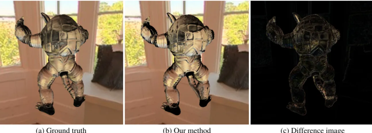
(a) Ground truth (b) Our method (c) Difference image
Figure 10: Comparison with ground truth without TIR. (Left) Ground truth. (Middle) Our method. (Right) The difference between the two images. Although our result is plausible, some artifacts are visible due to our assumptions (see Sec. 3.2).
(a) Only depth (b) Our BTDF (c) Our BTDF without filtering without filtering with NDF filtering Figure 11: Comparison of transport methods: (Left) Specular transport with fixed mipmap level look up into the environment map based on depth traveled by the ray inside the object. (Mid-dle) Specular transport with our spherical Gaussian model of the BTDF. (Right) Our approach, also accounting for the lobe tranport. Our technique accounts well for the low-pass filtering effect of the BTDF on the geometry at the second interface.
Figure 1 shows the Bunny model with several BTDF exponents κDγ to illustrate the range of materials that can be achieved with our method. Our model supports modification of the BTDF’s exponent κD
γ in real-time, allowing artists to adjust the glossiness of the re-fractions to obtain a desired appearance.
Figure 12 summarizes the performances of our method. While our method for rendering rough materials is on average two times slower than rendering of specular materials [Oliveira and Brauw-ers 2007], we achieve a speed up of several ordBrauw-ers of magnitude compared to ground truth raytracing for comparable image quality. Since our technique is mainly excuted in a fragment shader, we in-dicate the number of pixels covered by the geometry in addition to the number of triangles. The graph in Figure 12 illustrates the ren-dering cost of each pass of our algorithm, as well as the renren-dering cost for purely specular materials [Oliveira and Brauwers 2007].
5.2 Limitations
Spatially-varying BTDFs: Our method can handle spatially-varying BTDFs at the first interface as specified by a texture map. However, our light transport approximation in the object is not com-patible with spatially-varying BTDFs at the second interface. Screen-space filtering: Since we rely on a screen-space algorithm to estimate the NDF at the second interface, our method is restricted to geometry that lies inside the view frustum.
Models #Tri #Pix Specular Rough (Our) GTruth
Sphere 20k 80k 1.4 ms 3.5 ms 47 s
Bunny 65k 58k 2.2 ms 7.2 ms 47 s
Monkey 70k 76k 6.3 ms 11.9 ms 46 s
Buddha 100k 65k 10.8 ms 19.6 ms 51 s
Dragon 100k 87k 10.0 ms 19.8 ms 65 s
Figure 12: This table shows the performances of our methods ac-cording to the number of triangles #Tri and the number of pixels #Pix covered by the geometry. We compare the timings of our method to a GPU specular refraction algorithm and to the ground truth rendering generated with Optix. Ground truth timings are given for 512 samples per pixel.
6
Conclusion
We have presented a new algorithm for rendering transparent ob-jects with rough surfaces. Our algorithm runs in real-time, and ren-ders plausible images. Our algorithm is based on two contributions: a new formulation for the scattering function at the interface, and a combination of cone tracing and geometry filtering to approximate the exiting rays at the exiting interface.
Our new formulation for the scattering function at the interface is an approximation of the actual BTDF [Walter et al. 2007], using spherical Gaussians. The approximation is better suited for convo-lution with the incoming light and the geometry.
Our combination of cone-tracing with geometry filtering allows us to approximate the light transport inside the transparent object, ag-gregating the normals over the area intersected by the bounding cone of the refracted rays. We then convolve the resulting nor-mal distribution function with the BTDF of the surface to obtain a new scattering function, that we use to query the pre-convolved environment lighting.
Our method runs in real-time, can handle complex objects and ac-counts for the integration that happens due to scattering at the ex-iting interface. In future work, we would like to extend this ap-proach to handle spatially varying BTDFs and total internal reflec-tions. Our approach for filtering the normals at the exiting interface
(a)κDγ = 20000 (b)κDγ = 90 (c)κDγ = 24 (d)κDγ = 6.4 Figure 13: Additional results with Bunny and Armadillo models under various environment maps for different roughness. could also be applied for indirect illumination of complex reflective
objects.
7
Acknowledgments
This work was supported in part by NSF grant 0924968, ANR grant ANR-07-MDCO-001, and the ExploraDoc program. We also ac-knowledge additional support from NSF grant 1011832, NVIDIA through a professor partnership award and graphics cards, and equipment and funding from Intel, Adobe and Pixar. The envi-ronment map used in this paper were provided by Bernhard Vogl (http://dativ.at/lightprobes/). The models used in this paper come from the Stanford 3D scanning respository, except the monkey model which comes from the Blender project.
References
AMANATIDES, J. 1984. Ray tracing with cones. Computer Graphics (SIGGRAPH ’84) 18, 3, 129–135.
BLINN, J. F. 1977. Models of light reflection for computer synthe-sized pictures.Computer Graphics (SIGGRAPH ’77) 11, 3, 192–198.
CAO, C., REN, Z., GUO, B.,ANDZHOU, K.2010. Interactive Render-ing of Non-Constant, Refractive Media UsRender-ing the Ray Equations of Gradient-Index Optics. Computer Graphics Forum (EGSR pro-ceedings) 29, 4, 1375–1382.
DAI, Q., WANG, J., LIU, Y., SNYDER, J., WU, E.,ANDGUO, B. 2009. The dual-microfacet model for capturing thin transparent slabs.
Computer Graphics Forum 28, 7, 1917–1925.
EISEMANN, E.,ANDD ´ECORET, X.2006. Fast scene voxelization and applications. InSymposium on Interactive 3D Graphics and Games (I3D), 71–78.
HAN, C., SUN, B., RAMAMOORTHI, R.,ANDGRINSPUN, E.2007. Fre-quency domain normal map filtering.ACM Transactions on Graph-ics (SIGGRAPH 2007) 26, 3, 28.
HEIDRICH, W., LENSCH, H., COHEN, M. F.,ANDSEIDEL, H.-P. 1999. Light field techniques for reflections and refractions. In Euro-graphics Symposium on Rendering.
IHRKE, I., ZIEGLER, G., TEVS, A., THEOBALT, C., MAGNOR, M.,AND
SEIDEL, H.-P. 2007. Eikonal rendering: Efficient light transport in refractive objects. ACM Transactions on Graphics (Siggraph’07) 26, 3 (Aug.), 59.
KAUTZ, J., V ´AZQUEZ, P.-P., HEIDRICH, W.,ANDSEIDEL, H.-P. 2000. Unified approach to prefiltered environment maps. In Eurograph-ics Workshop on Rendering, 185–196.
OLIVEIRA, M. M.,ANDBRAUWERS, M. 2007. Real-time refraction through deformable objects. InSymposium on Interactive 3D Graph-ics and Games (I3D), 89–96.
PARKER, S. G., BIGLER, J., DIETRICH, A., FRIEDRICH, H., HOBE
-ROCK, J., LUEBKE, D., MCALLISTER, D., MCGUIRE, M., MORLEY, K., ROBISON, A.,ANDSTICH, M.2010. Optix: a general purpose ray tracing engine.ACM Transactions on Graphics 29, 4, 1–13.
RAMAMOORTHI, R.,ANDHANRAHAN, P. 2001. A signal-processing framework for inverse rendering. InSIGGRAPH ’01, 117–128.
RAMAMOORTHI, R.,AND HANRAHAN, P. 2002. Frequency space environment map rendering. ACM Transactions on Graphics (SIG-GRAPH ’02) 21, 3, 517–526.
SUN, X., ZHOU, K., STOLLNITZ, E., SHI, J.,ANDGUO, B.2008. Inter-active relighting of dynamic refrInter-active objects.ACM Transactions on Graphics (SIGGRAPH ’08) 27, 3, 1–9.
TOKSVIG, M. 2005. Mipmapping normal maps. journal of graphics, GPU, and game tools 10, 3, 65–71.
WALTER, B., MARSCHNER, S. R., LI, H.,ANDTORRANCE, K. E.2007. Microfacet models for refraction through rough surfaces. In Eu-rographics Symposium on Rendering.
WANG, J., REN, P., GONG, M., SNYDER, J.,ANDGUO, B. 2009. All-frequency rendering of dynamic, spatially-varying reflectance.
ACM Transactions on Graphics 28, 5.
WYMAN, C.2005. An approximate image-space approach for inter-active refraction.ACM Transactions on Graphics (SIGGRAPH 2005) 24, 3, 1050–1053.