a)
Corresponding author
1
Precise through wall angular position sensor compatible with cryogenic temperature for space launcher
A.Carapelle1,a), N.Martin1, T.Chantraine1
1
Centre Spatial de Liège, Université de Liège, Angleur, 4031, Belgium
Abstract
A new rotation sensor is developed and tested for the next generation of Ariane space
launchers. It aimed at measuring accurately the angular position of an admission valve (target sensitivity of 0.01°) from cryogenic (4K) to room temperature without recalibration. The measurement has to be done contactless and through pipe walls. Innovative electromagnetic application, cryogenic design and data treatment allows reaching the specifications.
Keywords: contactless, angular position, cryogenic, calibration
1. Introduction
For the next generation of engines in Ariane space launcher family, precise measurement of the angular position of the fuel (for ex. liquid oxygen) admission valve must be done to allow optimization of engine’s regime; the targeted sensitivity is 0.01°. The measurement must be done through pipe’s wall (304L stainless steel). The sensor must work between cryogenic (4K) and room temperature without recalibration; the measurement drift induced by
temperature must be less than 0.1° of angle in the whole temperature range. To meet allowed data storage of embedded microcontroller, the calibration parameters must be reduced to the minimum. Besides electronic readout components must meet space qualification
2
Linear and rotational through wall sensor are commercially available; but they do not achieve requested accuracy at cryogenic temperature and their electronics do not fulfill space
qualification requirements. Therefore a new sensor has to be developed.
To achieve these requirements the same through wall electromagnetic sensing method previously developed for Ariane 5 CRP sensor[1] is used; it’s adapted it to cylindrical geometry and cryogenic conditions. A new data treatment and electronic readout have also been added to reduce the number of calibration parameters.
2. Electromagnetic measurement principle
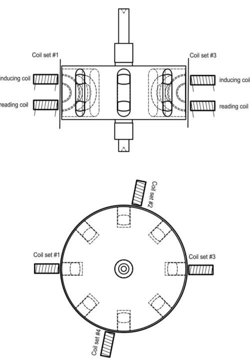
The measurement principle is based on the close of a magnetic circuit. Four pairs of coils are mounted on the cylindrical wall of the pipe; the first coil of each pair provides an inducing sinusoidal signal (current regulated, to avoid wiring resistance problems) and the second coil receives the signal when the magnetic circuit is closed. Closing of the magnetic circuit is achieved by embedding a series of 8 half tori into the rotor of the valve. Each half of the torus closes the magnetic circuit when it comes in front of a pair of coil.
3
Figure 1 - Geometrical description
The half tori are cut from Magnaperm tori; this material is chosen because of its electromagnetic properties at cryogenic temperature [2].
The Signal from the coils is handled by a resolver based on spaced qualified component AD2S280 (used onboard Herschel satellite [3]).
4
The device has to work from 4K to room temperature and has to avoid mechanical failure and blocking due to difference of thermal expansion coefficient of all components. To achieve this goal, the half tori are glued in hollows of the rotor; the glue used is cryogenic compatible Stycast 2850.
The rotor axis and its cylindrical surrounding pipe were co aligned; due to thermal dilatation these axes could lose their alignment, in which case the signal from the coils would be affected. To avoid this, a bushing is used to maintain the rotor axe’s position. To ensure this bushing would not block the rotation at cryogenic temperature Vespel SP-1 is chosen.
Due to the geometrical requirements, coils are tailor made with 0.1mm gauge copper wire and glued with IMI 7031 low temperature varnish.
4. Measurements results
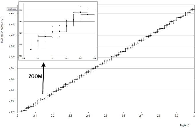
Figure 2 shows the resolver outputs, at room temperature, for 80 steps of 0.01° rotation. The rotation is imposed by a calibrated precision motor (Newport PR50PP). For each step of 0.01°, the resolver output signal is increased by its minimal increment (0.00244Volts, the minimal measurable voltage. It corresponds to 1 LSB of ADC used) or keeps its value (variation less than 0.00244 Volts). In that case, the next step of 0.01° always lead to an increase of the output value. It can be assume that the sensitivity is slightly higher than 0.01°.
5
Figure 2 - Accuracy at room temperature
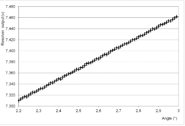
The setup is then placed in cryostat filled with liquid Helium. Figure 3 gives the measurement at liquid Helium temperature (4 K).
6
Figure 3 - Accuracy at liquid Helium temperature
During the filling with liquid Helium all the electronic are shut down; then turned on after temperature stabilization at 4 K. As the mechanical parts have moved during the rapid cool down phase, when the electronic is turned on, the initial position (0° angular position) isn’t the same and therefore in figure 3 and 4, the angle values given are not absolute value. The important information on these two figures is that sensitvity for angular measurement is slightly higher than 0.01° in both cases.
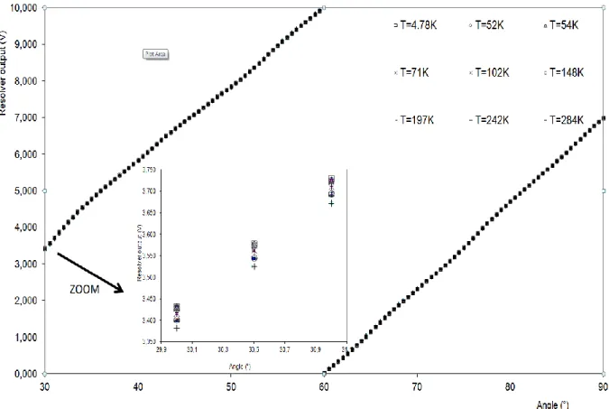
Afterward the whole setup is warmed up from 4 K to room temperature and we proceed to angular position measurement at different temperatures. Figure 4 gives the curves at different temperatures.
7
Figure 4 - Response curves at different temperatures
The measured drift induced by the temperature lead to an increase of the absolute error. The measured increase of the absolute error was partially due to our particular cryogenic setup: the precision motor that imposed the angular position couldn’t sustain cryogenic temperature and has to be maintained at room temperature; therefore the rotational motion is transmitted to the sensor at cryogenic temperature by a 130 cm long axis. The axis is passing through an hollow cylinder that supported the whole setup (including the rotor and the sensor). During the warm up phase, temperature profiles of the axis and cylinder are probably different; inducing a torque between the axis (which imposed the angular position) and the cylinder (which support the sensor). Therefore, we can assume that the decrease of sensitivity is partially due to the particular setup used. It’s safe to assume that the real sensitivity is between 0.01° and 0.1° but we can’t give a precise value.
8
5. Data treatment
The signal at the output of the resolver circuit should have been a linear function of the angular position of the rotor. Unfortunately, as one can see on figure 4, it isn’t perfectly linear. It is due to the facts that the real rotors and tori are not perfect shapes and the variation from ideal geometry induces nonlinearity in the resolver output. Besides, magnetic properties of materials (Magnaperm and coils) are not perfect and also induce nonlinearities. If we could impose very strict tolerances on mechanical manufacturing and on magnetic properties, these non linearities would be less than the foreseen sensitivity of 0.01° for the angular position. The easiest solution to overcome the non linearity is to record a calibration table for all the requested position but this would have lead to a 36000 numbers calibration file. This amount of data exceeds the space launcher dedicated embedded microcontroller data storage
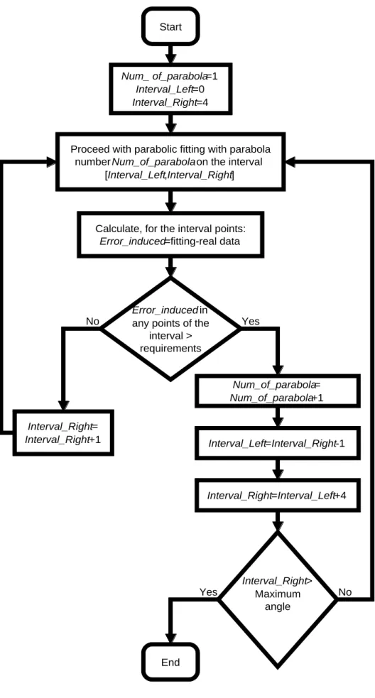
capabilities. We reduce the amount of data by fitting a succession of second order polynomial (parabola) to the data measured in a calibration phase. A software takes the 36000 points and proceed to the fitting: it starts by fitting a first parabola to the first 4 data points and calculates the difference between the fitted equation and the real measurement; if this difference is less than the requirements (0.01° in our case), the software calculates the fitting including one more points in the data set until the difference exceeds the requirements, in that case a new parabola fitting is calculated with the 4 next points… Figure 5 gives this algorithm.
9 Start
Proceed with parabolic fitting with parabola number Num_of_parabola on the interval
[Interval_Left,Interval_Right]
Error_induced in
any points of the interval > requirements
Num_ of_parabola=1 Interval_Left=0 Interval_Right=4
Calculate, for the interval points:
Error_induced=fitting-real data Interval_Right= Interval_Right+1 No Num_of_parabola= Num_of_parabola+1 Yes Interval_Left=Interval_Right-1 Interval_Right=Interval_Left+4 Interval_Right> Maximum angle No Yes End
10
With real data these particular algorithm find 13 parabolas for our particular setup for a rotation from 0° to 45°; this means that only 39 numbers have to be stored in the
microcontroller instead of 4500. This process allows reducing the data storage by a factor of 115 in our case.
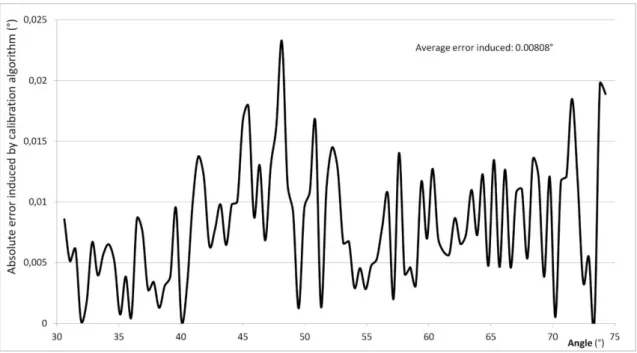
Figure 6 gives the increase of absolute error induced by the use of this algorithm.
Figure 6 - Error induced by calibration algorithm
6. Conclusions
In the real rocket’s engine; the very maximum allowed error in the angular position of the valve is 0.1°; our sensor is developed to have sensitivity ten times better. Even in the worst case if all the decreases of sensitivity during the warm up phase are coming from our sensor, we still can use it on the real engine.
The next phase will be to build an industrial version of our sensor and to submit it to full qualification test campaign (vibration, EMC compatibility …) but as the technology as already been qualified for Ariane 5, no particular problem is foreseen.
11
7. Acknowledgement
This study has been requested by Techspace Aero and has been funded by Walloon Region in Belgium.
8. References
[1] SABCA specification A4-ST1271K14-A-001-SABC Procurement specification for « compte rendu de position » Ariane 5, 1992
[2] QUACH Hung P., CHUI Talso C. P., in Low temperature magnetic properties of Metglas
2714A and its potential use as core material for EMI filters : Proceedings of Space Cryogenics Workshop No20, Girdwood, Alaska , United States of America, 18 September
2003.