UNIVERSITÉ DE MONTRÉAL
DESIGN AND IMPLEMENTATION OF APODIZED AND UNAPODIZED FREQUENCY CONVERTERS IN BULK APERIODICALLY POLED NONLINEAR MATERIALS
AMENEH BOSTANI
DÉPARTEMENT DE GÉNIE PHYSIQUE ÉCOLE POLYTECHNIQUE DE MONTRÉAL
THÈSE PRÉSENTÉE EN VUE DE L’OBTENTION DU DIPLÔME DE PHILOSOPHIAE DOCTOR
(GÉNIE PHYSIQUE) JUIN 2016
ÉCOLE POLYTECHNIQUE DE MONTRÉAL
Cette thèse intitulée :
DESIGN AND IMPLEMENTATION OF APODIZED AND UNAPODIZED FREQUENCY CONVERTERS IN BULK APERIODICALLY POLED NONLINEAR MATERIALS
présentée par: BOSTANI Ameneh
en vue de l’obtention du diplôme de : Philosophiae Doctor a été dûment acceptée par le jury d’examen constitué de :
M. LEBLOND Frédéric, Ph. D., président
M. KASHYAP Raman, Ph. D., membre et directeur de recherche M. KÉNA-COHEN Stéphane, Ph. D., membre
DEDICATION
Dedicated to my parents,
for all their love, endless supports and accepting my decisions in life
in memory of
ACKNOWLEDGEMENTS
Foremost, I am grateful to God for the good health and wellbeing during my PhD studies.
My deepest gratitude is to my supervisor and research director, Prof. Raman Kashyap for his excellent guidance, caring, patience, and providing me with an excellent atmosphere for doing research. I have been fortunate to have an advisor who gave me the freedom to explore on my own, and believed in my potentials and supported me by his immense knowledge and his great ideas.
I would like to thank all of my colleagues and friends at Advanced Photonics Concept Laboratory (APCL) whom I have worked and collaborated with. I would like to especially acknowledge Dr. Amirhossein Tehranchi for his invaluable support and his motivation during my PhD and in doing research and writing this thesis. He has been always there to listen and give advice. In addition, I would like to thank Dr. Meenu Ahlawat who has been a constant support during my PhD, in the lab and personal life. I feel gratified to have been surrounded by wonderful colleagues: Dr. Mohamad Diaa Baiad, Dr. Mathieu Gagné, Dr. Elton Soares de Lima Filho, Jérôme Lapointe, Tahereh Ahmadi Tame, Victor Lambin Iezzi, and Dr. Krishnamoorthy Pandiyan. I would like to give a special acknowledgement to the technicians at Poly-Grames Research Center and Laboratoire de Micro-fabrication: Mr. Jules Gauthier, Dr. Alireza Hajhosseini Mesgar and Mr. Christophe Clément for their support in fabrication work.
I take this opportunity to extend my sincerest thanks to all of my colleagues and teammates at Polytechnique Montréal for their valuable technical and emotional supports during all these years.
Finally, I am deeply thankful to my family providing me unfailing support and continuous encouragement throughout my years of study and through the process of researching and writing this thesis. Without them, this thesis would never have been written.
RÉSUMÉ
Cette thèse porte sur l’étude, la conception et la fabrication de convertisseurs de fréquences à large bande pour la génération efficace de seconde harmonique (SHG) et de somme de fréquences (SFG) sur des dispositifs non-linéaires en quasi-accord de phase (QPM). Les dispositifs de QPM comprennent des réseaux de domaines inversés, qui fournissent un accord de phase non critique pour la conversion de fréquences dans les matériaux non-linéaires. Pour créer des cristaux à QPM, le coefficient non-linéaire de second ordre est périodiquement inversé à l’aide d’une méthode de polarisation périodique. Avec d’excellentes propriétés telle sa non-linéarité, le cristal de niobate de lithium (LN), utilisé pour les simulations et la fabrication de ces travaux de recherche, est un des meilleurs candidats pour les dispositifs à QPM. Les matériaux périodiquement polarisés uniformément tel le niobate de lithium périodiquement polarisé (PPLN), possèdent une largeur de bande d'acceptation spectrale et thermique étroite. La largeur de bande étroite limite la conversion de fréquences pour une longueur d’onde spécifique d’un laser pompe et nécessite l’utilisation d’un contrôleur de température pour maximiser l’efficacité de conversion. En addition, les conversions de fréquences pour plusieurs longueurs d’onde simultanément ainsi que le réglage de la longueur d’onde de pompe sans réglage de température sont restreints par les PPLN uniformes. Les réseaux à pas variable (chirped) et step-chirped dans le LN ont été récemment proposés pour pallier la limitation de la bande passante des doubleurs de fréquences basés sur la SHG. Les réseaux chirped peuvent être conçus pour obtenir une largeur de bande souhaitée et enlever la nécessité de l'installation du régulateur de température dans le montage expérimental. Cependant, ces dispositifs souffrent d'ondulations et de fluctuations dans leurs réponses spectrales. L'application d'apodisation sur les réseaux chirped est proposée pour diminuer les ondulations dans la réponse de ces dispositifs, dans lesquels les changements de coefficient non linéaire effectif en fonction de la longueur converge vers zéro au niveau des rebords du réseau. Dans cette thèse, les méthodes d’ingénieries non linéaires effectives appropriées pour supprimer des ondulations des convertisseurs à large bande sont explorées. La mise en œuvre d'une fonction d'apodisation souhaitée sur les convertisseurs à large bande basés sur la variation du rapport cyclique est examinée en profondeur. La dépendance de la phase du champ electrique sur la génération de seconde harmonique à l’endroit de la région polarisée dans un réseau apériodique est explorée théoriquement. Il a été démontré pour la première fois
que la bande spectrale de conversion de doubleurs de fréquences chirped apodisés dépend du lieu de la région polarisée dans la période de réseaux. La conception adéquate pour minimiser les ondulations et pour réaliser une fonction de non-linéarité souhaitée pour un réseau chirped apodisé a été proposée, ce qui améliore la tolérance aux erreurs de fabrication.
Il a été également démontré qu'une autre approche alternative pour adapter et contrôler efficacement la non-linéaire dans les convertisseurs à large bande est de focaliser le faisceau gaussien dans un réseau chirped non-apodisé. Il a été démontré théoriquement et expérimentalement pour la première fois que le changement spectral de l'intensité lumineuse en focalisant un faisceau gaussien peut être traduit en une fonction d'apodisation et supprime l'ondulation (ripple) dans la réponse à large bande de convertisseurs chirped. Pour démontrer cette approche, un réseau chirped dans un morceau de LN a été fabriqué pour fonctionner dans une bande de SH de 30 nm pour la bande de communication (C-band), en utilisant un design de réseau step-chirped. Il a été vérifié qu’en augmentant la focalisation, une réponse sans ondulation est progressivement réalisée sur une bande passante de 6 dB de >5nm, avec une taille de faisceau de 20 m. L'augmentation de la focalisation rétrécit également la bande passante des réseaux, car elle réduit l'intensité de la lumière rapidement loin du point focal. Cependant, le réglage en continu est également démontré en déplaçant le point focal dans le réseau step-chirped.
En outre, il a été prouvé que les PPLN chirped apodisés spécialement conçus, basés sur le positionnement particulier des régions polarisées dans les périodes, présentent une réponse réciproque dans les spectres de SHG, pour les directions de chirped vers l’avant et vers l’arrière. Les résultats de simulations sont comparés à un autre PPLN chirped apodisé pour lequel le placement des régions polarisées est dévié de la position optimale. Expérimentalement, pour la première fois, la conversion de fréquence des dispositifs fabriqués est obtenue sur une largeur de bande de 30 nm dans les deux sens pour montrer la réciprocité de la conception.
Enfin, le convertisseur de bande indépendant de la température est utilisé, pour la première fois, pour la génération de SHG et SFG d’un puissant laser à fibre à onde continue (CW laser) avec une largeur de bande de quelques nanomètres centrée autour de 1550 nm, sans l'aide d'un régulateur de température. Il a été démontré que ce dispositif est insensible à la dérive de fréquences du laser et des variations spectrales lorsque la puissance intégrée augmente. De plus, la puissance quadratique de SHG par rapport à la puissance de pompe est obtenue en utilisant un
PPLN step-chirped avec la source de puissance élevée. Il a été également démontré que ce dispositif est entièrement en accord de phase simultanément pour les deux processus de conversion non-linéaire de second ordre : SHG et SFG. Il a été démontré que l'ensemble du spectre d'un laser pompe peut être converti en onde de SFG par l'ingénierie d'une fonction de transfert appropriée pour un réseau. À l’aide d’un laser monochromatique accordable comme signal de contrôle et en réglant à plus de 30 nm dans la bande de communication, une conversion de fréquences à large bande super-accordable du puissant laser CW dans la gamme de 770-778 nm est réalisée. L'effet de focalisation a également été pris en compte dans l'élaboration de la théorie de la conversion de faisceau laser pour un maximum d'efficacité de conversion non-linéaire.
ABSTRACT
This thesis focuses on research study, design and fabrication of broadband frequency converters based on second harmonic generation (SHG) and sum frequency generation (SFG) in nonlinear quasi-phase-matched (QPM) devices. QPM devices based on domain-inverted gratings provide noncritical phase matching for frequency conversion in nonlinear media. For creating QPM crystals, the second-order nonlinear coefficient is periodically reversed by periodic poling method. Lithium niobate (LN) crystal with excellent properties such as high nonlinearity is one of the best candidates for QPM devices, which has been used for the simulations and fabrication in this research work. Conventional uniform periodically poled materials such as periodically poled lithium niobate (PPLN) crystals possess a narrow spectral and thermal acceptance bandwidth. The narrow bandwidth limits the frequency conversion for a specified pump wavelength and necessitates the use of a temperature controller to maximize the efficiency. In addition, uniform gratings restrict simultaneous frequency conversion for several wavelengths and tunability of the pump wavelength without temperature tuning. Therefore, chirped and step-chirped gratings in LN were recently proposed to overcome the bandwidth limitation of frequency doublers based on SHG. Chirped gratings can be engineered to obtain the desired bandwidth and remove the necessity of controlling the temperature in the experimental set-up. However, these devices suffer from ripples and fluctuations in their spectral responses. Applying apodization in chirped grating is suggested to diminish the ripples in the response of these devices, in which the effective nonlinear coefficient changes, as a function of length, smoothly to zero at the edges of the grating. In this dissertation, methods for engineering proper effective nonlinearity are explored to suppress ripples of broadband converters.
Implementation of a desired apodization function on broadband converters based on duty ratio variation is deeply examined. The dependence of SH electrical field phase on the place of poled region in an apreriodic grating is explored theoretically. It has been demonstrated for the first time that the spectral conversion bandwidth of apodized chirped frequency doublers depends on the place of the poled region within the period of gratings. The proper design to minimize the ripples and achieve a desired nonlinearity function for an apodized chirped grating has been proposed which improves the tolerance to fabrication errors.
It has been also shown that another alternative approach for shaping effective nonlinearity in broadband converters is focusing the Gaussian beam in a un-apodized chirped grating. It has been demonstrated theoretically and experimentally for the first time that the spatial change of light intensity by focusing of a Gaussian beam can be translated to apodization and suppresses the ripple in the wideband response of a chirped grating. For demonstration of this approach, a chirped grating in bulk LN has been fabricated to operate in a 30-nm SH bandwidth for the communication band, using a step-chirped grating (SCG) design. It has been verified that by increasing the focusing, a ripple-free response is progressively achieved over a 6-dB bandwidth of >5nm, with a beam waist of 20 µm. Increasing the focusing also shrinks the bandwidth of gratings as it reduces the intensity of light rapidly far from the focal point. However, continuous tuning is also demonstrated by changing the focal point within the SCG.
Also, it has been proved that a specially-designed apodized chirped PPLN based on the particular positioning of poled regions within the periods exhibits a reciprocal response in the SHG, for up-chirp and down-up-chirp directions. The simulation results are compared with another apodized chirped PPLN in which the placement of poled regions deviates from optimum positions. Experimentally the frequency conversion is obtained over a 30-nm bandwidth of fabricated device in both directions to show the reciprocity of the design.
Finally, the temperature-independent broadband converter is used for the first time to generate SH and SF of a CW high power fiber laser with a few nm bandwidth centered at 1550 nm without using temperature controller. It has been shown that this device is insensitive to laser frequency drift and spectral variations as the integrated power raises. In addition, quadratic SH power with respect to the pump power is obtained using step-chirped (SC)-PPLN for the high power source. It has been also demonstrated that this device is fully phased-matched simultaneously for both second-order nonlinear up-conversion processes, SHG and SFG. It has been shown the entire BW of a pump laser can be converted to an SF wave by engineering a proper transfer function for a grating. Utilizing a tunable monochromatic laser as a control signal and tuning over 30 nm in the communication band, a super-tunable broadband frequency up conversion of the high power CW laser in the range of 770-778 nm is realized. The effect of focusing is also has been considered in developing the theory of laser beam conversion for maximum up-conversion efficiency.
TABLE OF CONTENTS
DEDICATION ... III ACKNOWLEDGEMENTS ... IV RÉSUMÉ ... V ABSTRACT ... VIII TABLE OF CONTENTS ... X LIST OF TABLES ... XIII LIST OF FIGURES ... XIV LIST OF SYMBOLS AND ABBREVIATIONS ... XVIII LIST OF APPENDICES ... XXICHAPTER 1 INTRODUCTION ... 1
1.1 Motivation ... 1
1.1 Literature review ... 2
1.2 Objectives ... 7
1.3 Overview ... 7
CHAPTER 2 INTRODUCTION TO NONLINEAR OPTICS AND FREQUENCY CONVERTERS ………10
2.1 Basics in nonlinear optics ... 10
2.2 Wave Equations ... 13
2.3 Nonlinear Coupled Wave Equations for SFG and SHG ... 17
2.4 Phase matching ... 22
2.4.1 Birefringence phase matching ... 24
2.4.2 Quasi-phase matching ... 25
2.6 Apodization ... 31
2.7 Gaussian beam ... 37
CHAPTER 3 FABRICATION OF PERIODICALLY POLED LITHIUM NIOBATE ... 41
3.1 Lithium niobate ... 41
3.2 Fabrication process ... 44
CHAPTER 4 ARTICLE 1: ENGINEERING OF EFFECTIVE SECOND-ORDER NONLINEARITY IN UNIFORM AND CHIRPED GRATINGS ... 56
4.1 Abstract ... 56
4.2 Introduction ... 57
4.3 Theory ... 58
4.4 The case of apodized uniform gratings ... 61
4.5 The case of apodized chirped gratings ... 64
4.6 Effect of domain error in proposed apodized chirped structure ... 68
4.7 Conclusion ... 70
CHAPTER 5 ARTICLE 2: TAILORING AND TUNING OF THE BROADBAND SPECTRUM OF A STEP-CHIRPED GRATING BASED FREQUENCY DOUBLER USING TIGHTLY-FOCUSED GAUSSIAN BEAMS ... 71
5.1 Abstract ... 72
5.2 Introduction ... 72
5.3 Theory ... 73
5.4 Design and fabrication ... 74
5.5 SH Spectrum tailoring by focusing with different beam waists ... 76
5.6 SH spectrum tuning by changing the focal point in the grating ... 78
CHAPTER 6 ARTICLE 3: DESIGN, FABRICATION AND CHARACTERIZATION OF A SPECIALLY APODIZED CHIRPED GRATING FOR RECIPROCAL SECOND HARMONIC GENERATION 81
6.1 Abstract ... 82
6.2 Introduction ... 82
6.3 Theory and design ... 83
6.4 Fabrication and characterization ... 86
6.5 Results and discussion ... 88
6.6 Conclusion ... 90
CHAPTER 7 ARTICLE 4: SUPER-TUNABLE, BROADBAND UP-CONVERSION OF A HIGH-POWER CW LASER BASED ON Χ(2) PROCESSES IN AN ENGINEERED NONLINEAR PHOTONIC CRYSTAL ... 91
7.1 Overview ... 91
7.2 Abstract ... 92
7.3 Introduction ... 92
7.4 Theory and Design ... 94
7.5 Experiment and Results ... 98
7.6 Conclusion ... 103
CHAPTER 8 GENERAL DISCUSSION ... 105
CHAPTER 9 CONCLUSION AND RECOMMENDATIONS ... 109
9.1 Direction for future work ... 110
BIBLIOGRAPHY ... .111
LIST OF TABLES
LIST OF FIGURES
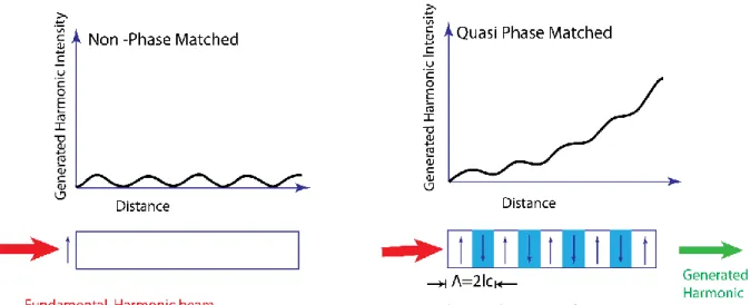
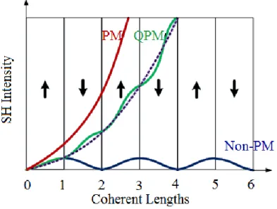
Figure 1.1: Quasi phased matched structure and its generated harmonic intensity compared to
none-phase-matched crystal. lc represents the coherent length. ... 3
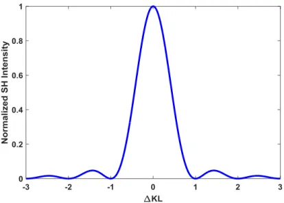
Figure 2.1. Normalized SH intensity vs. phase mismatch. ... 21
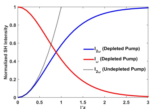
Figure 2.2 Normalized FH amplitude and SH efficiency in depleted case are in comparison with SH efficiency in un-depleted case. ... 22
Figure 2.3: Sketch of phase matching concept when all dipoles radiate in phase to build up the SHG. The fundamental wave is plotted in red color and has a well-defined phase, propagating in the crystal. The induced dipoles all emit light at the double frequency of fundamental harmonic with a phase determined by the fundamental wave [64]. ... 23
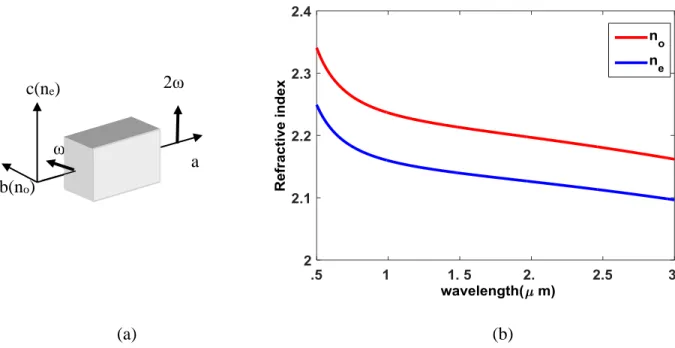
Figure 2.4: a) Configuration for achieving phase matching in a birefringent LiNbO3 (no˃ne). b) ordinary and extraordinary refractive indices for lithium niobate vs. wavelength. ... 24
Figure 2.5. Second harmonic intensity as a function of propagating distance for quasi-phase matching (QPM) by flipping the sign of the spontaneous polarization in every other coherence length compared to perfect phase-matched (PM) and non-phase-matched interaction (Non-PM). ... 26
Figure 2.6: a) Uniform grating. b) nonlinearity function in space. ... 27
Figure 2.7: Chirped grating. ... 28
Figure 2.8: Schematic of step-chirped grating. ... 29
Figure 2.9: Bandwidth of chirped PPLN compared to uniform PPLN. ... 30
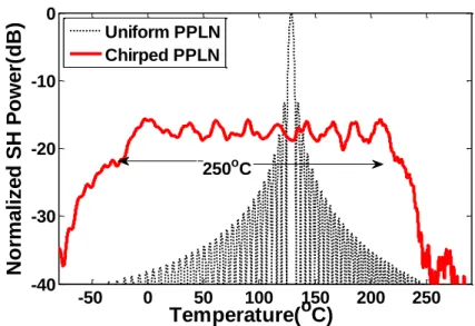
Figure 2.10: Thermal acceptance of chirped PPLN compared to uniform PPLN. ... 31
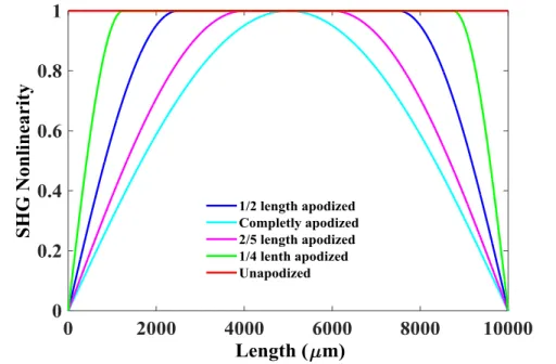
Figure 2.11: SHG nonlinearity versus length for apodization ratios. ... 33
Figure 2.12: SHG nonlinearity versus length for various functions. ... 34
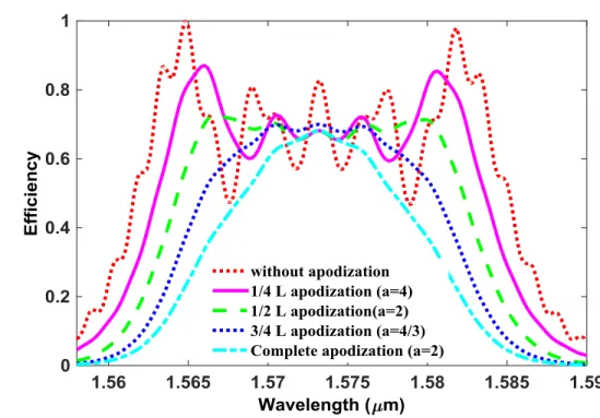
Figure 2.13: Normalized efficiency of SHG for different ratios of sine function appodization. ... 35
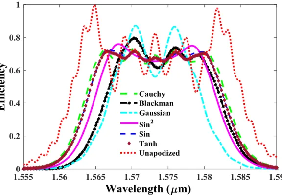
Figure 2.14: Normalized efficiency of SHG for various functions ... 36
Figure 2.16: Field amplitude of a Gaussian beam. ... 39 Figure 2.17. The field strength (A1) changes on-axis (r = 0) for different focusing parameters b 40
Figure 3.1.LiNbO3 structure in (a) as-grown state and (b) domain inverted state, where Ps and E represent the polarization and electric field direction respectively [74]. ... 42 Figure 3.2: Microscopic images of the fabricated mask with two different duty ratios. ... 45 Figure 3.3: Schematic of photolithography process of LN. ... 47 Figure 3.4: Photolithographic image under the microscope after development. The period is 18.6
μm. ... 49 Figure 3.5: Schematic of poling experiment setup showing the high voltage set-up and in-situ
optical monitoring using crossed polarizers, DAC: data acquisition card, PC: computer [79]. ... 50 Figure 3.6: Applied voltage during the poling process. ... 51 Figure 3.7: Images of samples under poling process in optical monitoring. a) Before sending the
pulse. b) After starting several pulses. c) After receiving more pulses than b. d) After completion of domain reversal area. ... 53 Figure 3.8: Schematic of revealing poled features in LN using HF etchant. ... 54 Figure 3.9: Inverted domain pattern in lithium niobate after etching under the microscope. The
period is around 18.5 µm. ... 54 Figure 4.1. Three supposed schemes when the poled region is in the right (Scheme I), middle
(Scheme II) and left (Scheme III) of a cell. C is the center of space region. ... 59 Figure 4.2 a) Effect of moving poled mark space with a duty cycle of 1/2 on the wavelength shift
from left to the right side according to b) in which, C, the central poled region changes from Λ/4 to 3Λ/4. ... 61 Figure 4.3. Relative wavelength shift for the three supposed structures in uniform grating
Figure 4.4. a) Normalized SH intensity response for 10-mm-long chirped APPLN crystal with different structure. b) Normalized bandwidth and ripple for structure I (red O), II (green>) and III (blue<). ... 65 Figure 4.5.a) Normalized SH intensity versus the FH using hyperbolic tangent apodized function.
b) Schematic of the proposed apodized chirped grating structures in APPLN composed of several cells. The middle un-poled (dark) space between nth and (n+1)th period changes as
1 1 ( )(1 ) (1 ) 2 2 n n n a a n a . ... 67 Figure 4.6. a) Influence of different types of errors in Structure II. b) Constant broadening errors
in 3 different structures. ... 69 Figure 5.1.(a). Schematic of the designed SC-APPLN. (b) Part of the fabricated sample viewed
under the microscope after etching. ... 76 Figure 5.2. a) Normalized effective second-order nonlinearity vs. grating length as a function of
focused beam waist and b-d) Normalized measured and simulated SHG efficiency vs. FH wavelength, for a focused light with different beam waists. In the legend “T” and “E” represent theoretical and experimental result, respectively. ... 78 Figure 5.3. Normalized measured and simulated SHG efficiency vs. FH wavelength for focused
light with a beam waist of 20 µm for four different focusing positions f, within the SC-APPLN device. In the legend “T” and “E” are theoretical and experimental data, respectively. ... 79 Figure 6.1. Schematic of apodized step-chirped grating, using CPS & OCPS design. The 10
sections and 18 subsections are divided by black and blue line, respectively. n is the number of periods in each section. Periods are separated by red dash line. Gray area with black arrow shows the domain-inverted region within each period while the white area with pink arrow shows the region with natural domain. ... 86 Figure 6.2.a) Experimental setup to evaluate SH response reciprocity with a CW pump laser,
EDFA: Erbium-doped fiber amplifier, PC: Polarization Controller and OSA: Optical Spectrum Analyzer. An AC-PPLN device is mounted on a temperature-controlled oven. b)
up-chirp and (c) down-chirp configurations, when the input and output fiber is interchanged. ... 87 Figure 6.3. Normalized simulated SH power versus FH wavelength for up-chirp and down-chirp
configurations using AC-PPLN with a) CPS and b) OCPS design. ... 89 Figure 6.4. Normalized measured SH power versus FH wavelength for up-chirp and down-chirp
configurations using AC-PPLN based on CPS. ... 90 Figure 7.1. Normalized transfer functions for different lengths of SC-PPLN at 25 ᵒC, considering
input pump (plane wave) at a wavelength of 1550 nm and a sweeping control signal. The inset shows the transfer function of the 13-mm-long SC-PPLN at T = 115 ᵒC. ... 96 Figure 7.2. Normalized transfer functions of the SC-PPLN considering un-focused beam (plane
wave) and focused beams at two different places along the gratings. ... 97 Figure 7.3. Experimental setup to evaluate SFG and SHG in an SC-PPLN with a high-power
fiber laser as a pump and a tunable laser as a control signal, EDFA: erbium doped fiber amplifier, PC: polarization controller, M: mirror, BS: beam splitter, PBS: polarization beam splitter, HWP: half-wave plate and OSA: optical spectrum analyzer. ... 98 Figure 7.4. a) Pump spectra for different integrated powers. b) Theoretical (T) and experimental
(E) results of simultaneous SFG and SHG when the pump and control signal are at 1550.16 nm and 1545 nm, respectively. The inset shows the region of tolerable drift in the pump central wavelength at 1550 nm for different signal wavelengths. ... 99 Figure 7.5. Overlaying of four experimentally observed spectra including SH of a pump (SHP) at
λ1=1550 nm and SH of four tuned signals at λS1=1532 nm, λS2=1536 nm, λS3=1560 nm and
λS4=1561 nm named as SHS1, SHS2, SHS3 and SHS4 and SF of the pump and signals
presented by SFP,S1, SFP,S2, SFP,S3 and SFP,S4. The inset shows theoretical and experimental
results for normalized SF power versus the wavelength. ... 101 Figure 7.6. SH spectra for 3 pump powers shown in Figure 7.4 (a). The inset shows output SH
LIST OF SYMBOLS AND ABBREVIATIONS
AC Apodized Chirped
AC-PPLN Apodized Chirped Periodically Poled Lithium Niobate APE Annealed Proton Exchange
APPLN Aperiodically Poled Lithium Niobate
BW Bandwidth
CPS Center-Poled Structure C-band Conventional Band
CW Continuous Wave
DAC Data Acquisition Card
DFG Difference Frequency Generation
DI Deionized
EDFA Erbium-Doped Fiber Amplifier EFP Electric Field Poling
FH Fundamental Harmonic
FWHM Full-Width Half Maximum
FWM Four-Wave Mixing
GaAs Gallium Arsenide HF Hydrofluoric
HWP Half Wave Plate
HV High Voltage
IPA Isopropyl Alcohol
KTP Potassium Titanyl Phosphate LCG Linearly Chirped Grating
Li Lithium
LiCL Lithium Chloride LiNbO3 Lithium Niobate
LN Lithium Niobate (LiNbO3)
M Mirror
MgO Magnesium Oxide
Nb Niobium
NLO Nonlinear Optic
OCPS Off-Center-Poled Structure OR Optical Rectification OSA Optical Spectrum Analyzer PBS Polarization Beam Splitter PC Polarization Controller
PPLN Periodically Poled Lithium Niobate
QPM Quasi Phase Matching
SC Step-Chirped
SAC Step-Apodized Chirped
SFG Sum Frequency Generation
SH Second Harmonic
SHG Second Harmonic Generation
UV Ultra-Visible
WC Wavelength Converter
WDM Wavelength Division Multiplexing
LIST OF APPENDICES
CHAPTER 1
INTRODUCTION
1.1
Motivation
In photonics, producing broadband light at high frequencies such as green and blue light has been of great interest in recent years. High-frequency broadband light has numerous applications in optical communications, optical information processing, and optical sensing in the past decades [1], [2]. One common way to produce such light is based on nonlinear frequency conversion, specially quasi-phase-matching (QPM) technique in which the nonlinear coefficient of crystal is reversed in specific periods [3], [4]. QPM in the form of uniform gratings has been investigated in many studies for up and down frequency conversions. However, uniform gratings have a small conversion bandwidth and are sensitive to temperature variation as well as angular rotation. Broadband wavelength converters in the form of spatially-modulated gratings, chirped and step-chirped periodically poled material have already been suggested to solve these limitations [5], [6]. Although utilizing chirped grating allows us to obtain a wider bandwidth but it introduces many ripples in the output response and significantly decreases the efficiency. Imposing some apodization has been suggested in chirped gratings [7] to decrease the fluctuations and ripples in second harmonic generation (SHG) responses. Increasing SH power is still a real problem as well as applying apodization on chirped gratings for realization. The broadband frequency conversion device requires a special design to be suitable for fabrication while decreasing the ripples. The ripple in the conversion efficiency is a function of wavelength in chirped gratings and depends strongly on apodization. All of these necessitate studying and realizing of a different kind of apodization in aperiodically poled material to achieve ultra-wide bandwidth devices, which fulfill the requirements by compromising between different criteria such as flatness, bandwidth, intensity and practicability of fabrication. In this dissertation, our aim is the realization of an apodized broadband wavelength up-converter (for high-power lasers with an output power in the order of 10’s-1000s of watts) based on SHG and sum frequency generation (SFG) in bulk lithium niobate (LN) using engineered step-chirped grating as a feasible fabrication approach.
1.1
Literature review
Second harmonic generation (SHG) was first demonstrated by Franken et al. in 1961 [8] by focusing a ruby laser beam at 694 nm in a plate of crystalline quartz shortly after demonstration of the first laser. The equations for SHG and other nonlinear interactions for monochromatic light are formulated by Armstrong and his colleague in a nonlinear medium using quantum-mechanical perturbation theory [9]. They derived coupled equations and solved it in phased matched velocities and imperfect phase matching. These nonlinear interactions require phase matching between fundamental and second harmonic wave vectors to compensate phase drift coming from the difference in their phase velocities due to material dispersion. Earliest approach to satisfy phase matching condition was using the birefringent material, in which two waves with orthogonal polarization can keep the same phase velocity for one wavelength due to different dispersion [10], [11]. As the refractive index is dependent on the temperature, phase matching for the wavelength of interest can be achieved by temperature tuning, named noncritical phase matching in which all polarization directions are along the two different crystal axes. Another technique for birefringence phase matching is tuning the angle of crystal or beams to adjust the phase velocities of propagation to fulfill the phase matching condition [12], [13]. In birefringence phase matching, the propagation directions and polarizations are severely constrained. The frequency converted light should be perpendicular to one or two polarized inputs named as the type II and type I phase matching, respectively. For SHG at a desired wavelength, the combination of temperature and angle tuning should be considered in proper crystal. In addition, the birefringence phase matching suffers from the birefringent walk-off in a critical phase matching (angle tuning). The SHG efficiency is a function of crystal’s properties and its length. Many theoretical and experimental works have been done on SHG for plane waves and focused beams [11], [12], [14]–[18]. Kleinman and his colleagues were the first to have examined the effect of a focused Gaussian laser beam on the SHG efficiency in nonlinear crystals. In their investigation, the birefringent walk-off in which intensity distribution drifts away from initial wave vector, with different beam tightness and focusing position, has been considered [17], [19], [20]. When light is focused into the crystal, the light is diffracted more rapidly when the spot size diminishes and leads to a reduction in the effective interaction length. Therefore, there is a tradeoff between the spot size and interaction length to get the maximum efficiency.
In a dispersive material, the fundamental and second harmonic waves have different phase velocities, and they shift π out of phase relative to each other over a distance called the coherence length (lc). If the sign of the nonlinear coefficient reverses in every other coherence length, it can locally transfer power to the second harmonic wave. This compensation of phase velocity dispersion in frequency conversion by the modulation of nonlinearity is called quasi phase matching (QPM). QPM provides non-critical phase matching at a specific temperature in the entire transmission band of the material and consequently does not suffer from the spatial walk-off. This technique also provides usage of materials with low birefringence for frequency conversion which was not efficient before QPM were introduced. Also, the largest nonlinear coefficient can be exploited [21], [22] and [23]. In addition to the type I and type II phase matching, type 0 phase matching, with the same polarization of input and output waves, is also possible using QPM. The quasi phase matched structure and mechanism of field accumulation in QPM are shown in Fig.1.1 and they are compared with a non-phase matched crystal.
Figure 1.1: Non-phase-matched crystal compared to quasi phased-matched structure and its generated harmonic intensity. lc represents the coherence length.
The QPM technique was proposed first time by Armstrong et al. in 1962 [9] for correction of the mismatch in nonlinear material. In 1972, Somekh and Yariv investigated the periodic modulation
in the boundaries of a thin film waveguide [21]. Experimentally, making QPM structures was first done based on stacking polished plates of nonlinear material together while alternating the sign of susceptibility in successive plates of GaAs at a Brewster angle [22]. The QPM is possible in a medium in which the nonlinear susceptibility can be patterned on a microscopic scale. Ferroelectrics and semiconductors are the best candidates for this purpose. While semiconductors such as GaAs are suitable for long-wavelength operation in the mid-IR, ferroelectrics have been widely used in the near IR and visible regions since the beginning of QPM devices. By enhancing the manufacturing ability on microscopic scale, many methods and experiments were undertaken to make QPM structures in ferroelectrics including electron beam writing [23], inversion during crystal growth [24], thermal inversion [25], surface impurity diffusion [26], ion exchange through a lithographic mask [27] and electric field poling [28]. Electric field poling in which the electric fields higher than the coercive field of ferroelectric material are applied to a periodic electrode pattern on the surface of a millimeter-thick wafer, is applied for both bulk materials and waveguides [29]. Nowadays, periodic domain inversion or poling by applying a high voltage at room temperature is the most common technique [30], [31]. The electrode pattern, which is an insulating grating pattern is made by lithography on the crystal which is then immersed into a liquid electrolyte. A high voltage is applied to create the electric field [32]. In the present work, electric field poling at room temperature was used for the fabrication of QPM devices in the form of chirped periodically poled lithium niobate (PPLN).
The most widely exploited ferroelectric for periodic domain inversion is lithium niobate (LiNbO3, LN) due to its largest nonlinear coefficient d33, among all other popular ferroelectrics such as lithium tantalate (LiTaO3, LT) and Potassium titanyl phosphate (KTiOPO4, KTP). It benefits from wide transparency from mid-IR into the near UV with an absorption edge at 320 nm. It is commercially available in three- and four-inch diameter substrates, convenient for lithographic patterning, processing and providing long interaction length. On the other hand, lithium niobate suffers from photorefractive damage in which the refractive index variation is induced by the generation of charges due to photo-ionization at relatively low intensities [33]. Photorefractive damage results in beam distortion within the PPLN and consequently affects the phase matching condition and particularly is severe for visible light [34]. In order to increase photorefractive damage threshold heating the crystal above the annealing temperature has been
suggested [35]. Also, magnesium oxide (MgO) doping can improve the LN resistant to photorefractive effect [36]–[38].
PPLN is used for frequency conversion in bulk and waveguide form. The first periodic poling based on the lithographic technique was only possible in waveguide geometries as it was based on the in-diffusion of titanium under the lithographic pattern and the domain gradually penetrated only a few microns below the surface of the substrate [26], [39]. However, by the emergence of electric-field poling techniques, the waveguide-usage limitation was overcome and the fabrication of PPLN was made also possible in the bulk form. Nowadays, annealed proton-exchanged and titanium in-diffusion after and before domain patterning (uniform grating) is a common way to fabricate PPLN waveguides [40], [41]. Waveguide PPLN has the advantage of having several times higher efficiency over bulk PPLN due to the high intensity from the beam confinement in the waveguide length. However, waveguides in PPLN can suffer from photorefractive damage at about 100 kW/cm2 [42] even with a small input power of around 100
mW [43], [44]. Therefore, for high power and ultra-short pulse laser pump with a high peak power, bulk PPLN is preferred. Bulk PPLN can tolerate several average kW input power and can avoid reaching the optical damage threshold. Also as long as the output power is the main concern, bulk QPM with higher input power can be utilized to compensate for lower efficiency. Further, the conversion efficiency in bulk configuration can be improved by optimum laser beam focusing using QPM. The conditions of focused light through the PPLN have been investigated theoretically and experimentally [45]–[47]. Focusing the light inside the quasi phase matched structure induces a central wavelength shift which can be fixed by modifying the period of QPM device [48].
The bandwidth of uniform poled structures is about few nanometers and similar to the birefringence phase matched converters, is inversely proportional to the length of a converter. The narrow bandwidth is not acceptable for many applications. There are many works on optical frequency converters to raise their bandwidths. In some schemes, multi-crystal design with the possibility of small angular detuning is used to satisfy the phase matching condition in crystals for different spectral components of input pulse [49], [50]. Segmenting the crystal and reversing the temporal or spatial walk-off in alternating segment of a multi-crystal is another approach to increase acceptance bandwidths in optical frequency converters [51]. Also, angular dispersion provided by a system of diffraction gratings and lenses or several prisms is exploited to guide
light at their phase matched angle and results in wider acceptance bandwidth [52], [53]. This method can also be applicable in QPM grating structures [54]. All of above approaches need very precise alignment and in the two last cases also need additional optical components. Another way to make a broader bandwidth device in a QPM grating is the use of segmented QPM waveguide [55]. Two fabrication techniques have been suggested for segmented grating structures. In one of them, several uniform structures with small period change are placed beside each other with a gap. In the second technique, the variation of waveguide width in a uniform grating is used to control the effective refractive index and consequently to satisfy phase matching condition for neighboring phase matched wavelengths. Also, the effect of using a constant-temperature gradient imposed along the bulk nonlinear crystal [56], [57] and uniform grating [6] have been studied to improve the tuning of the spectral bandwidth for a fixed crystal orientation. In 1990, Suhara offered a chirped grating structure to increase the SH bandwidth at the cost of reduced efficiency. In his proposed approach, instead of the identical periods, the period changes linearly within the crystal [5]. Chirped gratings not only have application in bandwidth broadening but also in compressing and stretching the second harmonic generated pulse relative to the input pulse [58].
Linearly chirped grating has two problems; Firstly, continuous change in the linear-chirped grating periods which is typically around 100 picometers makes it difficult for the fabrication [59]. Second problem is the noticeable ripples in the SHG conversion efficiency response [60]. Proposing step-chirped grating in which the change of period increases in steps and also applying some apodization to smooth ripples in the SHG efficiency response of the chirped PPLN waveguide have assisted to overcome the mentioned problems [7]. Apodization is the removal of the sharp edges in the spatial profile of nonlinearity in which the maximum of nonlinearity is brought down smoothly to zero at the grating edges. This leads to a reduction in ripples in chirped grating and diminishes the side-lobes of the sinc response of a uniform grating. Several schemes have been suggested for apodization in a uniform grating such as deleting domain reversal in some parts of the grating; waveguide tapering by placing grating into and out of the waveguide or integrating two directional couplers with a QPM grating; and by altering the duty cycle [59] ,[60]. An efficient method for apodization of step-chirped grating in waveguides was proposed theoretically by Tehranchi and Kashyap [7], which facilitates the process of fabrication and employs the variation in the duty cycle on the two edges of step-chirped grating. To
compensate for the efficiency reduction in the step-chirped gratings, a high-power laser with an average power in the order of several Watts to kWs can be used.
1.2
Objectives
As mentioned before, the development of apodized temperature-insensitive broadband QPM in bulk lithium niobate for high power application is the motivation of this work. In details, the purpose of this thesis is specified in the following objectives:
1. Development of the theory and design of engineered apodization in chirped gratings in poled crystals, e.g., lithium niobate for second harmonic generation
2. Spectral SHG response evaluation of the proposed apodized chirped grating devices 3. Investigation of a new approach to control the spectral SH response of a chirped grating
instead of fabricating an apodized chirped grating
4. Fabrication of apodized and un-apodized step-chirped gratings
5. Characterization of the device using SHG and sum frequency generation with a high power laser
6. Removing the temperature controller as a result of the device temperature-insensitivity.
1.3
Overview
In Chapter 1, after explaining the motivation for this dissertation, the literature behind this work is reviewed. The objectives and an overview of this dissertation explaining the general organization of the work are presented.
Chapter 2 introduces the basics of nonlinear optics relevant to frequency up-conversion. The theory of nonlinear optics and wave equations in nonlinear media is described. The concepts of phase matching and applicable techniques to satisfy it are presented. Continuous- and step- chirped grating, and apodization with different functions and ratios are introduced. Moreover, apodization using a Gaussian beam is explained.
In Chapter 3, the properties of lithium niobate as our working material are discussed and our fabrication approach for making PPLN devices based on electric field poling at room temperature is described in details.
Chapters 4 to 7 present four articles, addressing the objectives of this dissertation. Chapter 4 contains the first paper entitled “Engineering of effective second-order nonlinearity in uniform and chirped gratings”. This article addresses the first objective. This paper proposes the proper design to apply apodization in uniform and chirped gratings. It has been shown that when applying a desired apodization function, not only is the duty ratio but also the location of the poled region within the pitch is important. This is due to the amplitude and phase of the SH electric field being function of the duty cycles and position of the poled regions, respectively. The effect of displacement of the poled region position in the pitch on the SH conversion efficiency spectrum is investigated theoretically and numerically in the absence and the presence of domain errors. It is shown that our approach is robustly resistant to fabrication errors.
In Chapter 5, which is the second article entitled “Tailoring and tuning of the broadband spectrum of a step-chirped grating based frequency doubler using tightly focused Gaussian beams”, we propose the use of Gaussian beam to control the SH response of a step-chirped grating device. In this paper, SHG response characterization of the fabricated un-apodized device is obtained by the use of a tunable monochromatic laser. We address objective 3 and part of objective 4 for successful fabrication of step-chirped gratings.
Chapter 6 presents the design and fabrication of an apodized chirped grating while considering a proper position for a poled region within a pitch which is theoretically described in Chapter 4. This paper shows the reciprocal SH response as is expected from the theory and simulation in Chapter 4. This paper which is entitled “Design, fabrication, and characterization of a specially apodized chirped grating for reciprocal second harmonic generation” addresses the second objective and the part of the fourth objective, only the fabrication of an apodized grating.
In Chapter 7, a high power laser is used to pump the specially designed step-chirped grating to address the objectives five and six, which are the characterization of our chirped device with a high power laser considering the temperature insensitivity of the device. The temperature controller is removed in the experimental set-up as the device has a broad temperature acceptance bandwidth. The article entitled “Super-tunable, broadband up-conversion of a high-power CW laser based on χ(2) processes in an engineered nonlinear photonic crystal” in this chapter can be
divided into two experimental parts. In the primary part, we used a high power laser in addition to a tunable laser with neighboring frequencies around the pump as a control signal to be able to
tune the output wavelength of a chirped grating in the sum-frequency band. In secondary part the SHG of a broadband high power pump laser using the chirped grating is examined for different pump powers.
Chapter 8 provides a general discussion on the aspects of the four articles and a summary of technical points in this work. Finally, we conclude the work in Chapter 9 and it is followed with a view on future work and recommendations.
CHAPTER 2
INTRODUCTION TO NONLINEAR OPTICS AND
FREQUENCY CONVERTERS
2.1
Basics in nonlinear optics
When an electromagnetic wave enters a dielectric material, it interacts with the medium, causing a displacement of negative and positive charge centers in the constituent atoms and consequently creates dipoles. The dipole moment per unit volume is named the polarization (P ). The induced
polarization in materials depends on the strength of input electric field and medium crystal structure. At low intensities, the polarization depends linearly on input electric field. This linear dependence is proportional to the linear susceptibility χ(1) of material and determines the refractive index of the material. In this case, charges radiate their own electromagnetic wave with the same frequency as the input wave but with a phase delay, which results in a slower propagating output light compared to the original one due to its interference with the input wave. At high intensities, depending on the material structure, the dipoles do not oscillate sinusoidal for an applied sinusoidal electric field: in other words the generated polarization by dipoles is not equal for an applied electric field of +E0 compared to applied field of magnitude -E0. This
nonlinear response leads to the creation of other frequency components than the input one. The relation between the polarization and electric field can be described mathematically by means of the Taylor expansion
(1) (2) (3)
0 L NL
P E E E E E E P P , 2.1
wherePL 0 (1)E presents the linear part of the polarisation , and is the permittivity of free 0 space [61]. The linear part of polarization contributes to linear phenomenon causing by produced phase delay in the material such as refraction, diffraction, reflection and dispersion.PNLdenotes the nonlinear part of polarization. The quantities χ(2) and χ(3) are known as the second- and third-order nonlinear optical susceptibilities, respectively. The second term, proportional to the square of the electric field, is responsible for different kinds of frequency conversion, parametric fluorescence, and optical rectification. The second-order nonlinear interactions can occur only in non-centrosymmetric crystals that do not display inversion symmetry. On the other hand,
third-order nonlinear optical interactions can occur both in centrosymmetric and non-centrosymmetric media and give rise effects such as third harmonic generation (THG), the Kerr effect, Brillouin scattering, Raman scattering, self-phase modulation (SPM), soliton formation, cross-phase modulation (XPM) and four-wave mixing (FWM).
In order to understand different second-order nonlinear interactions which our focus in this dissertation is on, we consider an optical field strength E (which consists of two distinct
frequency components as
1 2
1 2
( ) t t .
E t E e E e c c., 2.2
where c.c. is the complex conjugate. The second order contribution to the nonlinear polarization strength in Eq. (2.1) can be written in the following form
(2) (2) 2
0
( ) ( )
P t E t . 2.3
By substituting (2.2) in (2.3), the second order polarization is given by
1 2 1 2 1 2 2 2 ( ) ( ) (2) (2) 2 2 * 0 1 2 1 2 1 2 (2) * * 0 1 1 2 2 ( ) [ 2 2 . .] [ ] i t i t i t i t P t E e E e E E e E E e c c E E E E . 2.4
If the polarization is expanded for different positive and negative frequency ωn, then:
(2)
( ) ( ) i nt
n n
P t P e . 2.5
The complex amplitudes of different frequency components are given by
( 21) ( 2 2) 1 2 1 2 (2) 2 1 0 1 (2) 2 2 0 2 (2) 1 2 0 ( ) 1 2 (2) * 1 2 0 ( ) 1 2 (2) * * 0 (0) 1 1 2 2 (2 ) (2 ) ( ) 2 ( ) 2 (0) 2 ( ) P E P E P E E P E E P E E E E . 2.6
The two first relations in Eqs. (2.6) describe second harmonic generation (SHG) of two pumps, the third and fourth one indicate on sum frequency generation (SFG) and different frequency generation (DFG). The last expression denotes on optical rectification (OR). For all frequency conversion equations (nonzero frequencies), also there is a response at negative frequency of each equation in (2.6) coming from the conjugation form of electric field which is not distinguishable. In practice, from these four different nonzero frequency conversions, typically, just one interaction occurs with a high-intensity input as the phase matching condition (This shall be explained in section 2.4 ) should be satisfied for frequency conversion which is not always easy to satisfy. Also, the interacting susceptibility (χint(2)) for the selected polarization should be
nonzero.
The susceptibility coefficient χ(m) for each allowed interaction is a (m+1) tensor and it consists of 3m+1 elements. For instance, χ(2) can be represented by a matrix of 3×3×3 and consists of 27
elements. Considering all kind of symmetries such as intrinsic permutation, lossless media symmetries and the Kleinman symmetry (the ijk(2) are not strongly dependent on frequency, if all the frequencies contribute to the interaction are far enough from any resonance frequencies of the nonlinear material) [62], the second-order susceptibility tensor can be simplified into a more convenient form called d-tensor, with components determined by
(2) 3 1 2 3 1 2 (2) (2) 3 2 1 3 2 1 2 ( ; , ) ( ; , ) ( ; , ) ( ; , ) il ijk ikj ijk d . 2.7
The indices i, j, and k indicate the field polarization directions of different axes x, y, and z. The indices j and k can be replaced by the index m, using the Voigt contraction. The contracted d-tensor has a more convenient form with 18 independent elements for nonlinear material with minimum symmetry. Therefore, the induced second-order nonlinear polarization for sum frequency generation in different directions is proportional to various components of applied electric field as 1 2 1 2 1 2 1 2 1 2 1 2 1 2 1 2 1 2 1 ( ) ( ) ( ) ( ) ( ) 11 12 13 14 15 16 ( ) ( ) ( ) 0 21 22 23 24 25 26 ( ) ( ) ( ) ( ) ( ) 31 32 33 34 35 36 ( ) ( ) ( 4 x x y y x z z y y z z y z x z z E E E E P d d d d d d E E P d d d d d d E E E E d d d d d d P E E E 2 1 2 1 2 ) ( ) ( ) ( ) ( ) ( ) x x y y x E E E E E . 2.8
In the case of SHG, the two frequencies are equal, and a coefficient of ½ is multiplied in the second term due to the use of one source.
Based on different classes of crystals, holding symmetries, the d-tensor elements can be reduced. For example for lithium niobate crystal which places in the 3m point group class, the d-tensor just has three nonzero elements; d31, d22 and d33 and in the form of tensor can be given by:
31 22 22 22 31 31 31 33 0 0 0 0 0 0 0 0 0 0 d d d d d d d d . 2.9
The quantity of nonzero elements and their places in the tensor are important in designing parametric devices as it can benefit from a maximum of the d-tensor element to maximize the conversion efficiency and the selection of proper polarizations.
2.2
Wave Equations
In order to understand and obtain wave equation describing propagation of light through a nonlinear optical medium, we begin with the Maxwell’s equations
ext D , 2.10 0 B , 2.11 t B E , 2.12 ext D H J t . 2.13
We are interested in the solutions of these equations in regions of space that contain no free charges, so that
0 ext
. 2.14
Also, the region does not contain any free currents, therefore 0
ext
J . 2.15
With the assumption of solving equation in nonmagnetic material, we have
H
B0 , 2.16
however, in nonlinear material experiencing induced polarization, the fields D and E are related by
0 ,
D E P 2.17
and in general, the polarization vector P depends on the local electric fieldE.
To derive the optical wave equation in the usual manner, we take the curl of the 3rd Maxwell’s
Eq. (2.12), and interchange the order of space and time derivatives on the right-hand side of the resulting equation. Using Eq. (2.13), (2.15), and (2.16) to replace B by
t D 0 , we obtain
0 2 2 0 t D E . 2.18
Substituting Eq. (2.17) in the above equation, to eliminateD , results in
2 2 0 2 2 2 1 t P t E c E . 2.19
This is the most general form of the wave equation in nonlinear optics [61]. This equation can be simplified under certain conditions. Using a vector calculus identity, the first term on the left-hand side of Eq. (2.19) can be rewritten as
2
( ) .
E E E
2.20
In linear optics, for an isotropic and homogeneous media with no charge, the first term on the right-hand side of this equation wiped out as the Maxwell’s equation D 0 results in E0. However, in nonlinear optics, this term cannot generally vanish even for isotropic materials, because of the general relation between D and E described in Eq. (2.17). Nevertheless, for transverse E field and infinite plane wave, this term can be dropped from the equation in nonlinear optics. Also, for slowly varying amplitude due to smallness compared to the second phrase in the right hand side of Eq. (2.20) can be ignored. Therefore, we can have this equation in the following form
2 2 2 0 2 2 2 1 E P E c t t . 2.21
By separating linear and nonlinear part of polarization as (1)
, NL
P P P 2.22
where (1)
P and PNL are the linear and nonlinear part of P
, respectively. The displacement field
(1) , NL
D D P 2.23.a
where the linear part is given by
(1)
0 L
D
E P . 2.23.bConsidering all of these quantities, the wave Eq. (2.21) becomes 2 2 (1) 2 0 2 0 2 NL P D E t t . 2.24
In the case of a lossless, non-dispersive medium, the relation between (1)
D and E is real and the frequency-independent dielectric tensor (1)
can be expressed as (1) (1)
D . E 2.25.a
For isotropic materials, this relation simplifies to
E
D(1)(1) , 2.25.b
where (1)
is now a scalar quantity, then wave Eq. (2.24) for an isotropic and dispersion-less material becomes 2 2 2 2 0 2 2 2 NL n E P E c t t 2.26
Eq. 2.26 is the inhomogeneous wave equation in the presence of a source. Actually, the nonlinear response of the medium acts like a source term, which appears on the right-hand side of this equation. In the absence of this source term, Eq. (2.26) converts to the form of wave propagation in a dielectric with the phase velocity of c / , where n 2
2 0 ) 1 ( 0 0 ) 1 ( 0 c n
and n is the (linear)
2.3
Nonlinear Coupled Wave Equations for SFG and SHG
For a dispersive medium, each frequency component of the optical field must be considered separately. In general, the total electric field and polarization are considered as a superposition of all different frequency components as
. . ] ) ω ( exp[ ) ( ˆ 2 1 . . ) ω exp( ) , ( ˆ 2 1 ) , ( n t cc i A e c c t i E e t E n n n n n n n n
r k r r r , 2.27 1 ˆ ( , ) ( , ) exp( ω ) . . 2 NL n n n n P r t
e P r i t c c . 2.28For each frequency component, Eq. (2.26) is valid, therefore 2 2 2 0 2 2 2 ( ) n NL n n P E E c t t . 2.29
Consider plane waves propagating in the z-direction, combining the two input waves at and 1 2
, the sum frequency is generated at . The present waves in the medium can be expressed by: 3
1 1 1 1 ( , ) ( ) exp[ ( )] . . 2 E z t A z i k zt c c 2.30.a 2 2 2 1 ( , ) ( ) exp[ ( 2 )] . . 2 E z t A z i k z t c c 2.30.b 3 3 3 1 ( , ) ( ) exp[ ( )] . . 2 E z t A z i k zt c c 2.30.c
where ki =ni/c and i = 1, 2 and 3 denotes the pump 1, pump 2, and generated SF wave, respectively. Ai is the slowly varying amplitude of the electric fields for the waves. The appropriate nonlinear polarization components for all contributing frequencies, according to Eq. (2.8), can be written as
(2) 3 0 1 2 1 2 1 2 0 1 2 1 ( ; , ) E 4 E 2 eff P E d E , 2.31.a (2) * 1 0 3 2 3 2 3 2 0 3 2 1 ( ; , ) E 4 2 eff P E d E E, 2.32.b (2) * * 2 0 3 1 3 1 3 1 0 3 1 1 ( ; , ) E 4 2 eff P E d E E . 2.31.c
For a negative uniaxial crystal of class 3m , the effective value of d for type I, II and zero phase matching can be given by deff d31sind cos sin 322 , deff d cos22 2sin 3 and deff d33, respectively. Here, for SFG in type I phase matching, pump 1 and pump 2 have a different polarizations and the polarization of one field is perpendicular to the polarization of generated SF wave. In type II phase matching, two pumps have the same polarization and their polarization are perpendicular to the generated SF wave and in type zero phase matching, the pumps and generated output have the same polarization.
We assumed that the Kleinman’s symmetry holds. Therefore, the same deff appears in all of three equations. Substituting Eqs. (2.30) and (2.31) into the wave Eq. (2.29) for example for SFG, and replacing by d2 2/dz2 as the field is just dependent on the z axis, we find:
3 3 1 2 3 2 (1) 2 ( ) 2 3 3 3 3 3 3 3 3 2 2 2 3 [(k ) z ] 1 2 2 ( ) 2 . . 4 . . i k z t eff i k t d A dA A ik k A e c c dz dz c d A A e c c c . 2.33
The third and fourth term in brackets on the left-hand side of this equation, cancel each other. Also using the slowly-varying envelope approximation,
2 2 , d A dA k dz dz 2.34
2 3 3 1 2 2 3 2 deff A exp( ) dA i A i kz dz k c , 2.35
where is called the phase mismatch. Using the same approach for the two pumps, k k1 k2 k3
other coupled equations can be obtained as 2 1 * 1 2 3 2 1 2 2 * 2 1 3 2 2 2 A exp( ) 2 A exp( ) eff eff d dA i A i kz dz k c d dA i A i kz dz k c . 2.36
This equation for SHG with the pump at frequency of ω1 and second harmonic at reduces to 2
two equations as 2 2 2 2 1 2 2 exp( ) eff d dA i A i kz dz k c (up-conversion process), 2 1 1 2 1 2 1 2 deff exp( ) dA i A A i kz dz k c (down-conversion process), 2.37.a 2.3.b
where i =1, 2 denotes the fundamental harmonic (FH) and the second harmonic (SH), respectively. Eqs. (2.36.a) and (2.36.b) represent the frequency up-conversion (+ 2) and down-conversion process (2 ), respectively.
The phase mismatch k for SHG of light in frequency of λ defined as
) ( 4 2 1 2 1 2 k n n k k . 2.38
Under the non-depleted condition in which the pump power stays constant (A1 ~ constant) Eq. (2.36) can be solved by direct integration to give the amplitude of the SH,
2 2 2 1 2 2 2 (0) 2 d A i kL 1 A e k c k . 2.39This assumption is valid whenever the conversion efficiency is not too large (around 10%) [63].
A1(0) is the input FH amplitude, and L is the length. The intensity of a light wave with the
amplitude A can be written as
2 2 1 A n c I o . 2.40
Using (2.39) and Eq. (2.38), results in calculating SH intensity
2 2 2 2 2 2 2 3 2 1 2 1 2 sin 2 2 (0) 2 eff o kL d I L I c n n kL 2 sinc 2 kL 2.41
where we define sincx sinx x .
Normalized SH intensity versus wave vector mismatch is plotted in Figure 2.1. The maximum SH intensity occurs when the mismatch is zero and decreases by increasing phase mismatch. For this reason, phase matching is very critical for having an effective conversion. In the next section, condition for phase-matching is explained in more details.
Figure 2.1. Normalized SH intensity vs. phase mismatch.
However, for the high conversion efficiency (more than 10%) the FH power depletion cannot be neglected. The pair of coupled Eqs. (2.36) should be solved simultaneously.
For the phase matching case (kL = 0), the solution exactly reduces to the well-known result (only when I2 (0) = 0) as follows
) ( tanh ) 0 ( ) ( 1 2 2 z I z I , ) ( sech ) 0 ( ) ( 2 1 1 z I z I , 2.42.a 2.42.b where is a normalized nonlinear coefficient defined as
1 1 0 2 2 (0) . eff d I cn cn 2.43
For low conversion efficiencies, 2 2
tanh ( L) ( L) and Eq. (2.41) reduces to maximum the SH intensity in Eq. (2.41) for phase matched one in the case of undepleted pump. The normalized SH efficiency I1,2/ I1 given by Eqs. (2.42) are shown in Figure 2.2
![Figure 3.1.LiNbO 3 structure in (a) as-grown state and (b) domain inverted state, where P s and E represent the polarization and electric field direction respectively [74]](https://thumb-eu.123doks.com/thumbv2/123doknet/2325223.30200/63.918.168.737.114.476/figure-structure-inverted-represent-polarization-electric-direction-respectively.webp)
