UNIVERSITÉ DE MONTRÉAL
DESIGN CHARACTERISTICS TO REDUCE INADVERTENT CROSS-AXIS
COUPLING DURING SIDE STICK HANDLING OF AIRCRAFT PITCH AND
ROLL AXIS CONTROL
MARIE-ÈVE CÔTÉ
DÉPARTEMENT DE MATHÉMATIQUES ET DE GÉNIE INDUSTRIEL ÉCOLE POLYTECHNIQUE DE MONTRÉAL
MÉMOIRE PRÉSENTÉ EN VUE DE L’OBTENTION DU DIPLÔME DE MAÎTRISE ÈS SCIENCES APPLIQUÉES
(GÉNIE INDUSTRIEL) JUIN 2012
UNIVERSITÉ DE MONTRÉAL
ÉCOLE POLYTECHNIQUE DE MONTRÉAL
Ce mémoire intutilé:
DESIGN CHARACTERISTICS TO REDUCE INADVERTENT CROSS-AXIS
COUPLING DURING SIDE STICK HANDLING OF AIRCRAFT PITCH AND
ROLL AXIS CONTROL
présenté par : Marie-Ève Côté
en vue de l’obtention du diplôme de : Maîtrise ès sciences appliquées a été dûment accepté par le jury d’examen constitué de :
M. AGARD Bruno, Doct., président
M. IMBEAU Daniel, ing., Ph. D., membre et directeur de recherche M. BASSETTO Samuel, Doct., membre
DEDICATION
Je dédie ce modeste travail et ma profonde gratitude à mon père pour l’éducation qu’il m’a prodiguée; avec tous les moyens et au prix de tous les sacrifices qu’il a consenti à mon égard, pour le sense du devoir qu’il m’a enseigné depuis mon enfance… À ma chère et précieuse amie d’enfance, Stéphanie Martel, pour son support inconditionnel… À ma mère pour son écoute et ses encouragements…
REMERCIEMENTS
On dit souvent que le trajet est aussi important que la destination. Les quatre années de maîtrise m'ont permis de bien comprendre la signification de cette phrase toute simple. Ce parcours, en effet, ne s'est pas réalisé sans défis. Je souhaite exprimer ma reconnaissance envers les gens qui m’ont aidé tout au long de ce parcours.
Ce travail m’a permis de découvrir d’avantage le domaine de l’aéronautique et d’échanger avec des personnes ayant des connaissances approfondies du domaine au sein de la compagnie Bombardier Aéronautique. Parmi celles-ci, je tiens particulièrement à remercier Sophie Duchesne pour m’avoir donné cette opportunité tout en travaillant au sein de son équipe. Non seulement elle a su partager une partie de son savoir, elle m’a encouragé et m’a donner support dans les moments difficiles.
Je tiens également à remercier Daniel Imbeau, mon directeur d’étude, pour sa compréhension, sa patience et ses conseils. Son savoir dans le domaine de la recherche m’a permis d’acquérir des connaissances pratiques qui vont me servir tout au long de ma carrière.
J’aimerais également remercier mes collègues de travail pour leur support et leurs encouragements. Plus particulièrement, j’aimerais remercier Aurélien Blond pour m’avoir aidé à récupérer les fichiers de mon disque dur lorsque mon ordinateur a cédé et à Philippe Doyon-Poulin pour son aide précieux qui a grandement contribué au fruit de ce travail.
Enfin, un merci particulier pour mes amis Phil Dixon et Jenny Maisonneuve qui ont su apporter aide et corrections tout au long de ce travail.
Grâce aux appuis et encouragements obtenu durant ce trajet j’arrive finalement à destination avec un bagage qui me servira pour de nouveaux parcours. Merci.
RÉSUMÉ
L’intégration d’un contrôle de vol tel que le mini-manche latéral (side stick) dans une cabine de pilotage occasionne des difficultés pour le pilote au niveau de la manœuvrabilité de l’avion. Il est plus difficile d’induire une commande dans un axe sans le faire par inadvertance dans l’axe opposé. Ce couplage des axes par inadvertance se fait plus facilement puisque les axes de roulis et de tangage (pitch) sont couplés. Le présent travail adresse trois caractéristiques de conception pour le montage du mini-manche latéral et de l’accoudoir pouvant aider à diminuer le couplage des axes par inadvertance. Les caractéristiques de conception prennent en considération la variabilité anthropométrique de la population pilote visée (1.57m femme à 1.9m homme). Sept pilotes ayant des mesures anthropométriques variées ont participé au test. Les tâches de vol demandées étaient des tâches sur un seul axe, soit en roulis ou en tangage qui ont été répétées pour chaque configuration. Pour comparer les configurations la variable durée ainsi que l’intégrale du couplage par inadvertance ont été analysées pour chaque manœuvre. Les résultats démontrent qu’un petit accoudoir, ne supportant qu’une partie de l’avant bras, diminue le couplage par inadvertance en roulis et la rotation de la boîte du mini-manche latéral vers l’extérieur diminue le couplage par inadvertance pour des manœuvres tangage.
ABSTRACT
Integrating a manual flight control inceptor with coupled axes such as the side stick within a flight deck creates challenges for the pilot to input a one-axis command without inadvertently inducing inputs in the opposite axis. The present paper studies three design features of the side stick and armrest setup believed to help reduce inadvertent cross-axis coupling occurrences. Design features address the aimed pilot population anthropometry (1.57m woman to 1.9m male) and their variability in upper segment measurements. Seven pilots of varying anthropometric sizes were asked to perform one-axis manoeuvres in pitch and roll for each setup configuration. To compare the setups both the duration and the definite integral of the unintended cross-axis input were processed and analyzed for each manoeuvre. Findings show that a short armrest reduces the occurrences of cross-axis input for the roll manoeuvre, whereas the side stick skew reduces inadvertent cross-axis coupling for the pitch manoeuvres.
TABLE OF CONTENT
DEDICATION ... iii
REMERCIEMENTS ... iv
RÉSUMÉ ... v
ABSTRACT... vi
TABLE OF CONTENT... vii
LIST OF TABLES ... x
LIST OF FIGURES... xi
LIST OF ACRONYMS AND ABREVIATIONS ... xiii
INTRODUCTION... 1
CHAPTER 1 CONTEXT ... 3
CHAPTER 2 LITERATURE REVIEW ... 5
2.1 Inadvertent cross-axis coupling – possible causes...5
2.2 Fly-by-wire technology ...6
2.3 Side stick controller ...9
2.3.1 Passive side stick...9
2.3.2 Active side stick ... 10
2.3.3 Bombardier side stick ... 10
2.4 Flight deck geometry... 12
2.5 Effects of side stick location on biomechanics... 14
2.6 Armrest functionality/usability ... 17
2.7 Armrest benchmarking... 18
CHAPTER 3 STUDY PREPARATION... 20
3.1.1 Short armrest design ... 22
3.1.2 Long armrest design ... 22
3.2 Side stick box skew... 24
3.3 Armrest channel... 24 CHAPTER 4 METHODS ... 26 4.1 Subjects ... 26 4.2 Materials... 27 4.3 Measurements ... 28 4.4 Experimental Procedure ... 29 4.5 Experimental design... 30 CHAPTER 5 RESULTS ... 33
5.1 Results per pitch and roll tasks ... 33
5.1.1 Roll task ... 33
5.1.2 Pitch task... 34
5.2 Results per study... 35
5.2.1 Study 1: Short (setup A) vs long armrest (setup B) ... 35
5.2.2 Study 2: No skew (setup B) vs skew (setup C)... 37
5.2.3 Study 3: No channel (setup C) vs channel (setup D) ... 38
5.3 Subjective results ... 38 5.3.1 Pilot questionnaire... 38 5.3.2 Observations ... 40 CHAPTER 6 DISCUSSION ... 42 6.1 Limitations... 44 6.2 Following tests... 46
CONCLUSION ... 47 BIBLIOGRAPHY ... 48
LIST OF TABLES
Table 1-1 Variables impacting inadvertent cross-axis coupling ...6
Table 1-2 Maximum wrist ROM (degrees) (Li 2002)... 16
Table 3-1 Pilot information... 26
Table 3-2 Pilot anthropometric measurements (cm) ... 27
Table 3-3 Reference points for anthropometric measurements ... 29
Table 3-4 Setup configurations ... 29
Table 3-5 One-axis manoeuvers... 30
Table 4-1 Roll task MANOVA (Wilks test) ... 33
Table 4-2 Univariate analysis - Roll task ... 33
Table 4-3 Pitch Task MANOVA (Wilks Test) ... 34
Table 4-4 Univariate analysis - pitch... 34
Table 4-5 Roll Bonferroni Post Hoc test – Area (left); Time (right) ... 35
Table 4-6 Pitch Bonferroni Post Hoc test – Area (left); Time (right) ... 35
LIST OF FIGURES
Figure 1-1 Design process ...3
Figure 1-2 ACT program vs C-Series development...4
Figure 2-1 Primary flight controls... 7
Figure 2-3 Fly-by-wire; Aircraft implementation ...8
Figure 2-2 Secondary flight controls...8
Figure 2-4 Bombardier side stick cant angles and switch position ... 11
Figure 2-5 Geometrical reference points ... 14
Figure 2-6 Force vector shoulder to hand (left hand)... 15
Figure 2-7 Arm position variation to side stick (sagittal view) (BM7013.08 2008)... 16
Figure 2-8 Armrest functionality... 18
Figure 2-9 Dassault 7X (left) and Airbus (right) ... 19
Figure 3-1 Pilot of small stature; Side stick neutral (left); Deflected side stick to softstop (right)21 Figure 3-2 Pilot of tall stature; Side stick neutral (left); Deflected side stick to softstop (right)... 21
Figure 3-3 Short armrest shape ... 22
Figure 3-4 Long armrest shape ... 23
Figure 3-5 Long armrest - inboard slant ... 23
Figure 3-6 Long armrest - tip of the armrest... 23
Figure 3-7 Outboard lateral skew of the side stick unit... 24
Figure 3-8 Long armrest – channel ... 25
Figure 4-1 Armrest & sidestick setup... 28
Figure 4-2 Illustrated computation of time & area ratios (example)... 32
Figure 5-1 Roll manoeuvre; Pilot 3 - Setup A – short armrest (left) & Setup B – long armrest (right) ... 37
Figure 5-2 Roll manoeuvre; Pilot 4 - Setup A – short armrest (left) & Setup B – long armrest
(right) ... 37
Figure 5-3 Pitch manoeuvre (slow); Pilot 6 - Setup B – no side stick skew (right) & Setup C – side stick skew (left) ... 38
Figure 5-4 Study 1 - support and comfort questionnaire... 39
Figure 5-5 Study 2 - support and comfort questionnaire... 39
LIST OF ACRONYMS AND ABREVIATIONS
ACT Active control technology ERP Eye reference point GRP Grip reference point SRP Seat reference point
REFS Reconfigurable engineering flight simulator ROM Range of motion
MFS Multifunction spoilers
BM Bombardier manual
BA Bombardier aerospace
FAA U.S. Federal aviation administration
TC Transport Canada
EASA European aviation safety agency MIL-STD Military standard
INTRODUCTION
In 1986, Bombardier Inc. dove into the aerospace industry by acquiring a government owned aerospace company, Canadair. Thereafter new acquisitions were made to ensure the growth of the company in the industry. Today, Bombardier Aerospace is very well established in the private and regional jet market segments and is the third largest company of its kind in the world. Competition has become very aggressive as new companies are entering the industry and existent companies are constantly pushing new technologies and products to keep or increase market shares. To continue the growth of the company, Bombardier recently entered a new market segment by launching the C-Series, a commercial aircraft that will accommodate 110 to 130 passengers. In addition to the increase in passenger capacity the C-Series will also be composed of the latest technology. For the first time, Bombardier will be integrating fly-by-wire technology into their aircraft for all control surfaces. This technology provides significant advantages such as a decrease in weight and an increase in reliability (Hegg 1992).
From a flight deck standpoint, the fly-by-wire system allowed Bombardier to change the conventional control column yoke used for pilot pitch and roll inputs to a side stick controller (Hanke & Herbst 1999). Incorporating the side stick within the flight deck clears the area in front of the pilot providing better display visibility, leg room (Hegg 1994), and allows for a more rapid manoeuvring (Mayer 2003). Although integrating the side stick into the cockpit has provided considerable benefits, it has created problems such as inadvertent inputs while attempting to execute a single axis manoeuvre (Mayer 2003). This problem occurs due to the coupled axis of pitch and roll. Inadvertent cross-axis coupling was not a problem with the conventional control column since the two axes were decoupled.
Unintended cross-axis coupling poses a significant problem, especially when such coupling negatively impacts aircraft handling performances. Possible causes of inadvertent cross-axis coupling are numerous. During initial development testing, specialists observed variability in anthropometric measurements and pilot flying aggressiveness to be contributors to inadvertent cross-axis coupling (Duchesne (1), Bombardier Aerospace (BA) personal communication August 2009). Additional causes may be due to the control law design and the sidestick design characteristics such as force and deflection amplitudes (Mayer 2003).
For all aircrafts, Bombardier is required to comply with a certification process imposed by authorities to allow sales and deliveries of their aircrafts; i.e. U.S. Federal Aviation Association (FAA), Transport Canada (TC), European Aviation Safety Agency (EASA). Among the numerous design certification requirements, the requirements related to cockpit controls are of importance when integrating and positioning a new pilot inceptor into the flight deck (FAA 27.777c). The requirement specifies that the design of controls and their position shall accommodate a civil pilot population with statures ranging from a 1,58m woman to a 1,91m male. In addition, Transport Canada recently issued a new requirement related to the side stick design. The requirement states that the side stick design shall include suitable arm support for side stick use and shall not cause significant unintentional cross-axis inputs (Transport Canada (TC) 2011).
A fixed side stick location design which caters to a population varying in anthropometric measurements creates a multitude of arm motion possibilities, therefore widening the spectrum of inadvertent cross-axis coupling occurrences. The arm support design should not only be interrelated with the side stick design, but should also consider the variation in arm movement kinematics (Wyllie 1988).
The intent of this study is to explore design characteristics that can reduce inadvertent cross-axis coupling while considering the variability in anthropometry.
CHAPTER 1
CONTEXT
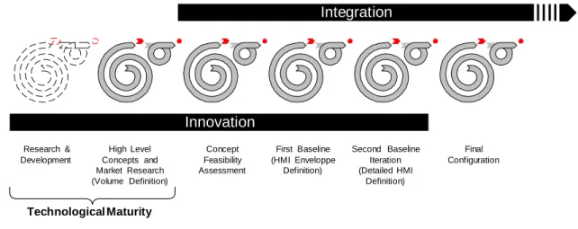
Figure 1 depicts the design process of a new technology from the innovation and development to the integration into an aircraft. Several iteration loops are included throughout the design process to validate and/or improve the requirements and design (BM1040.01.01.01, 2007). The development of the fly-by-wire technology followed such a process through a time span of several years. Bombardier invested in a development program for the fly-by-wire technology at the end of the 1990’s, namely the active control technology (ACT) program. The goal of this program was to develop the fly-by-wire technology and validate the proof of concept as a generic platform to eventually implement it to all Bombardier aircrafts (Duchesne (1), Bombardier Aerospace (BA) personal communication August 2009).
Concept Feasibility Assessment High Level Concepts and Market Research (Volume Definition) First Baseline (HMI Enveloppe Definition) Second Baseline Iteration (Detailed HMI Definition) Final Configuration Innovation Integration Research & Development Technological Maturity
Figure 1-1 Design process
The test vehicles used were a static re-configurable simulator and a Challenger aircraft with a side stick integrated to the existing flight deck. This configuration allowed to test the side stick while having the control column as a backup inceptor. Knowledge on side stick integration into a flight deck was limited due to the lack of information publicly available. Private companies do not publish their findings requiring more technical effort for the implementation. Initial side stick requirements were provided during the ACT program (Duchesne (1), Bombardier Aerospace (BA) personal communication August 2009).
Figure 2 provides a brief general depiction of what was completed on ACT versus what was completed during the C-Series development up to now. The use of an active side stick with a generic grip provided hardware to test and validate the first side stick requirements. As the development evolved and the knowledge of the arm static biomechanics was acquired the position of the side stick was refined to an optimal location for the aimed pilot population and the grip shape was designed to accommodate the location.
Throughout the design process inadvertent cross-axis coupling was observed when pilots were maneuvering with the side stick. Inadvertent cross-axis coupling is an undesirable behaviour as it may lead to increased workload for the pilot when trying to maneuver the aircraft. During the design, efforts were made to gear the design towards decreasing and/or eliminating inadvertent cross-axis coupling through control law algorithms and side stick design characteristics. It was observed that differences in anthropometric measurements influenced the introduction of inadvertent cross-axis coupling. This observation led to wanting to minimize the influence of anthropometry on inadvertent cross-axis coupling through design features/characteristics such as the armrest design. A better understanding of the dynamic arm biomechanics during side stick use was required for the development of these design characteristics (Duchesne (1), Bombardier Aerospace (BA) personal communication August 2009).
CHAPTER 2
LITERATURE REVIEW
2.1
Inadvertent cross-axis coupling – possible causes
Cross-axis coupling is defined as inducing an input through an inceptor which combines both the pitch and roll axis of the aircraft. A problem arises when one-axis input is intended, but the pilot inadvertently introduces an input in the opposite axis. The cause of unintended cross-axis coupling can be attributed to multiple sources such as the pilot characteristics, the displayed information and its’ interpretation, the side stick design, and/or the control law design (Mayer 2003; Duchesne (1), Bombardier Aerospace (BA) personal communication August 2009).
Pilot anthropometric measurements and flying aggressiveness (high gain vs low gain) are variables found to have an impact on inadvertent cross-axis coupling (Duchesne (1), BA personal communication August 2009). The torso and upper limb measurements impact the arm kinematic in relation to the side stick, therefore introducing arm biomechanical advantages for some and disadvantages for others. High gain pilots are defined to be aggressive and rapid whereas low gain pilots are smooth and slow in their flying habits (Mayer & Cox 2003; Duchesne (1), BA personal communication August 2009). Internal flight tests found that high gain pilots induced more inadvertent cross-axis coupling than low gain pilots. High deflection amplitudes of the side stick combined with rapid movements were also found to increase the probability of inadvertent cross-axis coupling occurrences (Duchesne (1), BA personal communication August 2009).
Another possible cause of inadvertent cross-axis coupling may be attributed to the delay in aircraft information availability on the display and/or the pilot perception of the information provided. The system delay in information availability of aircraft response may mislead the pilot into erroneously estimating the input required for a given aircraft response. Additionally, the presentation means on the display, i.e. symbols, have an impact on pilot perception and may also lead to undesired inputs (Mayer & Cox 2003).
The design of the side stick grip geometry as well as the force feel characteristics are variables that may influence undesired cross-axis coupling behaviour (Duchesne & Ouellette, BA personal communication August 2009). Cant angles are among the geometric design characteristics of the side stick and are defined as being the grip lateral and longitudinal angles
when the sides stick is at neutral (Figure 1-4). The shape of the side stick grip and the cant angles provide guidance in hand grip and arm position influencing the deflection orientation of the side stick where possible inadvertent cross-axis inputs may be introduced. The force feel characteristics such as the breakout force, damping, force gradient and deflection amplitudes are design elements that are believed to potentially drive undesired cross-axis inputs if forces are too high or too low. Table 1-1 lists the variables concerning the side stick geometry and force feel characteristics.
Table 2-1 Variables impacting inadvertent cross-axis coupling
Grip geometry Force feel
characteristics
Grip shape and orientation
Breakout force in pitch & roll Switch position Force gradient &
deflection amplitude Cant angles Damping
Side stick position relative to the pilot Switch breakout force
The design of the control laws is also a contributing factor to undesired inputs by the pilot. If the control law algorithms are sensitive the occurrences of inadvertent cross-axis coupling are more probable. Control laws are said to be sensitive when minimal side stick deflections induce an overestimated aircraft response (Mayer & Cox 2003).
Although control laws, side stick grip geometry design and force characteristics can contribute to the occurrence of cross-axis coupling, the present research will focus on the effects of anthropometry related to side stick handling and design features that help reduce these effects.
2.2
Fly-by-wire technology
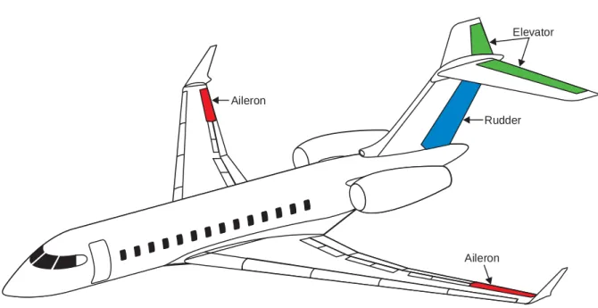
As opposed to conventional aircrafts where mechanical systems directly link pilot inputs to control surfaces, the fly-by-wire system relies on electronic signals to achieve the same pilot input to control surface link. The aircraft surfaces controlled by the inceptor are the two elevators and horizontal stabilizer for pitch input, and roll input achieved by the ailerons and the multifunction spoilers (MFS) (Figure 1-1 & 1-2). Electronic signals are transmitted from a flight control input, commanded by the pilot, to computers where signals are processed and sent to
actuators at each control surface. Flight control computers process the influx/incoming information from the pilot inceptor and the aircraft surfaces through control law algorithms designed in accordance with the aircrafts’ flying philosophy (e.g., stable vs unstable airframe). The company philosophy is to provide full authority to the pilot for manoeuvrability within the operational envelope of the aircraft and allows limited and excursions outside the operational envelope for unplanned operations such as collision or terrain avoidance (Niksefat 2011).
PRIMARY FLIGHT CONTROL
GX_10_001
Aileron
Elevator
Rudder
Aileron
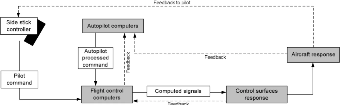
The implementation of fly-by-wire technology improves the stability and control of the aircraft since computers monitor the behaviour of the aircraft within the environment and consequently send signals to maintain aircraft stability without the pilot intent or knowledge (Tomczyk 2004). These signals constantly compensate by changing the control surface deflections during perturbation from the changing external environment, e.g. turbulence. When the autopilot is active, the dedicated autopilot computers replace the pilot commands and monitors the aircraft sending signals to the flight control computers that, in turn, process the signals to move the control surfaces in order to maintain aircraft direction (Figure 1-3) (Favre 1994).
Figure 2-3 Fly-by-wire; Aircraft implementation
GX_10_004 Multifunction Spoilers (4 per wing) Slats (4 per wing) Ground Spoilers (2 per wing) Flaps (3 per wing) Stabilizer Slats Multifunction spoilers Flaps Ground spoilers Horizontal stabilizer
The heightened aircraft stability provided by the control laws consequently improves the aircraft flying qualities and safety. As a result, pilot workload decreases because aircraft stability is performed and maintained by computers (Favre 1994). Limits of the control laws are set by the constraints of aircraft design and when these limits are reached or exceeded visual and/or tactile (e.g. haptic shaker of the side stick) cues are provided to the pilot. In summary, such technology reduces pilot training and decreases the need for having pilots with exceptional piloting skills, which in turn, translates to a cost reduction for companies who choose to purchase these aircrafts (Tomczyk 2004).
Another advantage is the weight saving. As mentioned earlier, the general structure of a fly-by-wire system is composed of computers and electromechanical actuators. Such a system weighs significantly less than a conventional mechanical system. In the aerospace industry weight is an important factor as it directly affects the performance of an aircraft, therefore the implementation of a fly-by-wire technology provides an opportunity to improve the performance of the aircraft.
2.3 Side stick controller
For the fly-by-wire technology two types of side stick inceptors exist in the industry, the passive and the active side stick.
2.3.1 Passive side stick
The passive side stick is composed of springs and dampers, which generate the force in relation to side stick displacement characteristics. Due to the side stick being mechanical, the springs and dampers limit the force gradient. This mechanical constraint limits the force capabilities to a fixed force gradient and is decoupled from the flight dynamics in terms of control force feedback (Hegg 1994). The passive side stick is a simple system that limits the tactile information to the pilot (Hanke & Herbst 1999). This tactile limitation is caused by the decoupling from flight process, co-pilot inputs, flight boundaries exceedance and autopilot inputs (Hanke & Herbst 1999).
Pilots are used to having tactile and visual feedback with the control column, therefore decoupling of tactile information from flight dynamics can lead to situational awareness problems specifically during critical situations where pilot workload is high (Hanke & Herbst 1999).
2.3.2 Active side stick
Contrary to passive side stick, the active side stick provides complete situational awareness by providing tactile forces calculated by the fly-by-wire computers during the flight (Hanke & Herbst 1999). Tactile feedback is obtained by electronic signals from aircraft system to the side stick through servo-motors. Since the active side stick is coupled with the aircraft dynamics it provides tactile and visual cues allowing for better handling and reduced pilot workload (Hegg 1994).
The active side stick system is complex and requires more technical effort to assure its reliability (Hanke & Herbst 1999). For this reason, most commercial aircraft companies decide to implement a passive side stick as it is less expensive.
2.3.3 Bombardier side stick
As a company strategy, Bombardier decided to implement a passive side stick into their aircraft. As mentioned above it is the simplest of both types requiring less technical effort to introduce, consequently less costly and less risky (Lortie, BA personal communication, June 2010). For confidentiality purposes specific values such as force and measurements are not provided.
For biomechanical purposes, the side stick design has cant angles in the pitch and roll axis in the neutral position. The integration of inboard cant angle is due to the limited capability of the forearm to go outboard and the forward cant angle is to enable the aft pitch movement (Black 1979; Bombardier manual 7013.08 (BM) 2008).
The baseline side stick is composed of three switches: Trim switch
Communication switch
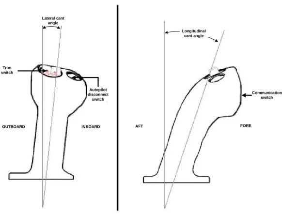
A rocker switch used to set the desired trim speed and a transmit switch one is used for communication with the air-traffic controller (Figure 1-4). The switch used for communication with the air-traffic controller is located at the crown of the side stick where the index or middle finger is positioned. The movement required to activate the switch is a lateral sliding movement. The trim switch used for the speed is located at the top of the side stick crown and is activated only when both halves of the switch are simultaneously deflected longitudinally in the same direction. The autopilot switch is a push-button for a quick disconnect of the autopilot or to take priority over flying manoeuvrability. This button is located beside the speed trim switch at the top of the crown (Figure 1-4).
Longitudinal cant angle Lateral cant angle Autopilot disconnect switch Trim switch Communication switch AFT FORE INBOARD OUTBOARD
Figure 2-4 Bombardier side stick cant angles and switch position
Being a passive side stick, the force gradient and side stick deflection amplitudes are constrained and limited by its mechanical composition. Flight control laws use inputs of stick position. In normal mode, the pilot can set a pitch attitude and a roll rate by deflecting the side
stick to the desired value and release the side stick; the airplane will maintain the aircraft attitude until additional inputs are made. This characteristic avoids the crew from having to maintain sustained forces when manoeuvring in the normal envelope. In direct mode the plane does not maintain the set pitch attitude or roll rate, therefore the pilot needs to maintain the stick force and position to maintain the desired airplane attitude (Niksefat 2011). The system mode changes from normal to direct mode upon system failure to ensure a safe flight and landing.
To avoid inadvertent side stick inputs when actuating the switches a breakout force in the pitch and roll axis is integrated. This initial breakout force also decreases the chances of unintentionally giving side stick inputs when it is accidentally bumped. Once the pilot deflects the side stick beyond the initial breakout force, all side stick inputs are processed and transmitted to the aircraft's control surfaces. The pitch operational limit is reached when the grip is deflected up to the aircraft operational limit and is indicated by an increase in stick spring force. The pilot has the authority to surpass the operational limit, if need be, up to the hardstop. Stick deflection between the operational limit and the hardstop is known as the aircrafts’ structural limit region in terms of pitch control envelope. The maximum spring force is attained at hardstop.
In the roll axis, the hardstop is reached at full deflection in either direction. The breakout and force gradient of the outboard roll force is 64% of the inboard roll force. The difference in force is explained by biomechanical optimization of force feel symmetry for one-handed lateral control (Dreyfuss 1993, Niksefat 2011).
The force characteristics of the switches are dependent on the breakout forces of the side stick in pitch and roll. To avoid inadvertent inputs in pitch or roll while activating a button, the breakout force of the switches are 50% less than the breakout force of the side stick (Black 1979).
2.4
Flight deck geometry
Anthropometric variations contribute to the complexity of flight deck design since the position of controls are required to be within functional reach for all pilots within a wide range population; i.e. 1.57m to 1.9m (FAA 25.777c).
To standardize the pilot position within the flight deck and obtain an optimal flying position in relation to the external vision, an eye reference point (ERP) is initially created to guide the design and position of controls (Figure 1-5). The ERP position varies among aircrafts
and is determined in relation to the flight deck structural envelope of the canopy ensuring sufficient head clearance as well as an optimal external vision through the windshield (BM7013.10 2004; Kennedy 1976; Military standard (MIL-STD) 1333B 1987).
From this design point, the displays, switches, knobs, pedals, tiller, and flight controls are positioned within visual access and physical reach for the aimed population. Taking into account the variability in segment measurements accounts for differences based on ethnicity and variability in anthropometric sizes (Kennedy 1976).
The evolution from the control column wheel to the side stick has a considerable impact on the flight deck layout and geometry. Due to the complexity of the adjustment mechanism it would require in order to assure its reliability, the side stick is set in one static position. Therefore, the side stick needs careful positioning in order to accommodate biomechanical capabilities of all pilots during side stick manoeuvrability while maintaining sufficient clearance with the surrounding environment (Kennedy 1976; Black 1979). Similarly to the eye reference point (ERP), a grip reference point (GRP) on the side stick is created to standardize the position of the hand on the side stick and to allow for an optimal side stick position and grip design (Figure 1-5) (Ouellette, BA personal communication June 2009; BM7013.08 Sidestick requirements, 2008). The GRP is located immediately underneath the side stick crown where the middle finger arrives.
The last design point is the seat reference point (SRP) used as a reference for seat design and position within the flight deck. The SRP point is the intersection of the back (12deg recline from vertical) and thigh lines (thighs at 7deg) as shown in Figure 1-5 (MIL-STD 1333B 1987; BM7013.10 2004).
Figure 2-5 Geometrical reference points
2.5 Effects of side stick location on biomechanics
Careful positioning of the side stick is important due to the influence it has on the arm biomechanics. The upper limb posture, hand grip and reach throughout the side stick deflection impacts the overall feel of the stick (Mayer & Cox 2003; Kennedy 1976). Varying upper body segment dimensions creates a multitude of different arm postures which not only impacts arm biomechanical dynamics but also grip strength capabilities and movement orientation throughout side stick deflection. This wide variation in upper body dimensions does not allow for an optimal side stick position for all pilots.
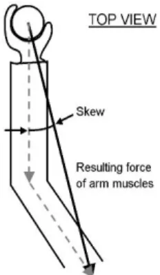
A relationship between the pitch axis movement direction of the side stick and the shoulder to hand force vector was observed through Bombardier internal research (Duchesne (2), BA personal communication September 2009). Since all pilots sit at ERP regardless of their anthropometric measurements, the orientation of the force vector consequently varies from pilot to pilot. The shoulder joint position varies and changes the force vector direction therefore impacting the deflection orientation of the side stick (Figure 1-6). Specialists have found through exploratory testing that pivoting the side stick box outboard laterally decreases the occurrence of inadvertent cross-axis coupling in the pitch axis. This counteracts the anthropometric limitation caused by the shoulder-hand force vector (Duchesne (2), BA personal communication September 2009).
Figure 2-6 Force vector shoulder to hand (left hand)
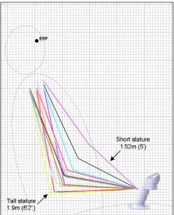
To position the side stick within an optimal location for the aimed population an internal study was conducted at Bombardier with 18 pilots and non-pilots of varying anthropometric sizes ranging from a 1.57m woman to a 1.9m male. Figure 1-7 illustrates the length of the segments of the upper limb of all 18 subjects and depicts the variability in arm position relative to the side stick. The arm was mapped following the assumption that the shoulder is abducted to achieve an elbow position directly aligned with the side stick. The angle of attack of the forearm to the side stick varies widely which in turn impacts the wrist neutral position. Pilots of shorter stature have steeper forearm angle of attack to the side stick, which induces radial deviation of the wrist (BM7013.08 2008).
Among the three impacted joints, the wrist angular position is the most important contributor to grip strength capability (Li 2002). The angle of the arm towards the side stick dictates the wrist position, therefore influencing the range of motion and force capability. According to the study conducted by Li (2002), the optimal position of the wrist for grip force capability was found to be 20deg extension and 5deg of ulnar deviation. Kattel (1996), however, found the neutral wrist position to be optimal for maximal force. This difference may be explained by the size and type of the grip used (Li 2002). Kattel (1996) also found that maximal grip strength was obtained with the elbow joint at 135deg and the shoulder at neutral; i.e. without flexion/extension and abduction/adduction. Substantial loss of strength, however, is observed when the wrist is in max ulnar and/or radial deviation (Li 2002).
Figure 2-7 Arm position variation to side stick (sagittal view) (BM7013.08 2008)
The kinematics of the wrist corresponds to an oblique plane relative to the anatomical plane which helps wrist mobility and agility; i.e. involving radial deviation with wrist extension and ulnar deviation with flexion (Li 2002; Li et al. 2004; Wolfe et al. 2006). This kinematic suggests that wrist movement in the pitch axis naturally involves cross coupling in the other axis. As the wrist is deflected from its neutral position in one direction (i.e. flexion-extension or radial-ulnar deviation) the range of motion (ROM) in the opposite direction becomes limited (Li 2004). Table 1-2 illustrates the maximum wrist deflection amplitudes in all axes. The radial deviation amplitude capability of the wrist is solely 23.5deg compared to the ulnar deviation of 51.4deg. The forward cant angle of the side stick provides greater radial deviation capabilities for a wider population.
Table 2-2 Maximum wrist ROM (degrees) (Li 2002)
Flexion Extension Ulnar Radial
The force required to move the side stick increases as the side stick is deflected. At full pitch deflection the force reaches the highest force, therefore a full grip is required throughout the pitch deflection of the side stick. To maintain an optimal wrist and grip position for force capabilities throughout the side stick deflection, the arm continually adapts to provide biomechanical advantages. This adaptation creates a large arm movement especially for small stature pilots.
Arm movements make side stick manoeuvrability less precise compared to the wrist movements for making and sensing small commands, leading to uncertainty as to the size of the command (Mayer 2003). Muscle groups for the roll are different than for the pitch making the simultaneous pitch and roll movements difficult (Mayer 2003).
Such side stick forces and arm movement during side stick deflection stresses the importance of incorporating an armrest to reduce possible fatigue and provide support for precise side stick inputs (Transport Canada FT-04 2011).
2.6
Armrest functionality/usability
In normal operation under normal flight conditions, the armrest is not only used for side stick handling, but also for resting when the autopilot is active (Figure 1-8). Figure 1-8 depicts a decomposition of the armrest functionality assuming a normal flight scenario, but also considering probable unplanned events where the side stick is deflected beyond the operational envelope. The hardstop is solely reached for exceptional scenarios where an obstacle needs to be avoided or for similar emergency conditions. High force combined with small deflection envelope from the operational limit to the hardstop does not allow for precise and fine movements. The armrest design needs to primarily provide arm support for side stick use throughout the whole side stick deflection envelope. As illustrated, when the autopilot is activated the armrest is used to rest, equating to 89% of the flight. The remaining 11% of the total flight, the armrest is used for side stick handling within the operational envelope. (Long and Duchesne BA personal communication 2009)
Armrest Functionality Scenario based on a 1hr30min flight Resting Side stick handling within normal envelope Maximum side stick deflection Frequency: 89% of total flight
- During flight the autopilot is activated and the armrest is used to rest
Frequency: 11% of total flight Takeoff estimated time: Up to 5 minutes
(Normally the autopilot is engaged between 400 and 1000ft)
Landing estimated time: 1 minute or less before touch down
(The autopilot will be disconnected at decision height approximately 200ft)
Other:
The side stick will seldom be usde during flight unless specific manoeuvers are required.
Frequency: Exceptional scenario Occurs when an obstacle needs to be avoided (terrain or collision avoidance)
Figure 2-8 Armrest functionality
2.7
Armrest benchmarking
According to Mayer & Cox (2003) a moveable armrest does not provide stability to the arm and provides a false sense of movement feedback, therefore requiring pilots to have a tighter hand grip on the side stick.
For comparable aircrafts, small and long armrests are used in the industry. Figure 10 illustrates the Dassault 7X and the Airbus armrest used to handle the side stick. For example, the Dassault 7X has a small armrest to support a portion of the forearm (Figure 1-9 - left) whereas the Airbus aircrafts have a long armrest supporting the entire forearm (Figure 1-9 - right).
Determining the correct design for a side stick armrest is of critical importance to abide by the requirements set by authorities and to provide the pilot with adequate support to ensure precision of flight manoeuvre and to minimize fatigue.
CHAPTER 3
STUDY PREPARATION
As described in previous chapters, the integration of the side stick within the flight deck geometry poses a challenge due to the variability in anthropometry. The side stick position is not optimal for all pilots and creates possibilities of inadvertent cross-axis coupling. Understanding the variables that may contribute to the occurrence of cross-axis coupling provides design opportunities to diminish the impact or influence of these variables. The biomechanics of the pilot arm throughout the side stick deflection was considered to determine the design characteristics to be studied. For confidentiality reasons armrest measurements are not disclosed in the present paper.
3.1 Short versus long armrest
The first design characteristic studied is the size of the armrest. Both short and long armrests exist in the industry. Variation in stature and segment size of the arm results in several different arm movement and displacement throughout the side stick deflection. The high forces combined with the large displacement amplitude of the side stick design forces the hand-wrist position to be near neutral allowing for optimal force capability. Maintaining a near neutral position of the wrist throughout the stick deflection suggests an arm movement rather than a wrist movement. The arm movement is of greater amplitude for pilots of small statures because their arm posture at neutral side stick is straighter than average and tall pilots (Figure 2-1). Pilots of average to tall stature translate their arm aft and abduct their arm outboard during aft deflection of the side stick (Figure 2-2).
The short armrest design provides support for the mid-portion of the forearm allowing the arm to move freely throughout the side stick aft deflection without interference. The long armrest, however, provides support for the whole forearm for pilots ranging from average to tall statures (Figure 2-1). Due to the large arm movement of small pilots and the initial position of the arm, they would be required to use the forward edge of the long armrest for support to allow full side stick deflection without arm interference with the armrest (Figure 2-2).
Figure 3-1 Pilot of small stature; Side stick neutral (left); Deflected side stick to softstop (right)
Figure 3-2 Pilot of tall stature; Side stick neutral (left); Deflected side stick to softstop (right)
3.1.1 Short armrest design
The small armrest was created to support the mid-portion of the forearm during side stick neutral position while allowing full range of motion of the arm throughout the side stick full deflection. Using the CATIA engineering tool (Dassault Systemes, France) the arm movement of a small and tall person were simulated to determine the dimensions of the armrest. First, a minimal distance from the fully aft deflected side stick to the armrest was considered to provide to avoid clash between the side stick and armrest. Thereafter, the length of the armrest was dictated by the elbow position of the shortest pilot when the side stick is in neutral position.
To determine the width of the armrest the medial and lateral rotation of the arm throughout the roll manoeuvres was simulated. Figure 2-3 provides an illustration of the small armrest shape.
3.1.2 Long armrest design
The dimension of the long armrest and the inboard slant was inspired by the existent long armrest in the industry, i.e. Airbus. The armrest shape and dimensions were determined considering the flight deck design and limitations (Figure 2-4).
The inboard cant angle of the side stick at neutral causes a rotation of the forearm. An inboard cant angle of the armrest would naturally support the forearm and provide directionality during pitch axis deflections. An inboard slant was incorporated to the armrest cushion with the
assumption that a small slant angle on the armrest does not negatively impact roll manoeuvers (Figure 2-5).
The forward edge of the armrest was angled to allow a comfortable support for pilots of small stature using the forward edge of the armrest for support (Figure 2-6).
Figure 3-4 Long armrest shape
5deg
Figure 3-5 Long armrest - inboard slant
2in
3.2 Side stick box skew
The second design characteristic studied is the side sticks longitudinal axis rotated 5deg outboard relative to aircraft forward longitudinal axis (outboard skew). As mentioned earlier, observations suggest a correlation between shoulder width and the occurrence of inadvertent roll inputs during pitch inputs (Duchesne (2), BA personal communication September 2009). The variability in shoulder width introduces various force vector orientation towards the side stick, therefore the introduction of the skew must accommodate the majority of the population. Through benchmark of similar aircrafts and through analysis, an outboard skew of the side stick was found to be the midpoint force vector orientation for the aimed population (Figure 2-7).
Figure 3-7 Outboard lateral skew of the side stick unit
3.3 Armrest channel
The third design characteristic studied is a channel of lighter foam density embedded in the armrest. The goal of the channel is to provide a direction cue for pitch axis manoeuvres. The channel of lighter foam density was integrated into an armrest of the same design and dimensions of the long armrest described in the section above (section 1.7.1.2 Long armrest design).
The long armrest design was reused in this study to compare an armrest with and without a channel. The channel orientation was aligned with the pitch axis orientation of the side stick unit, i.e. outboard skew (Figure 2-8).
CHAPTER 4
METHODS
4.1
Subjects
Participating subjects were Bombardier pilots with varying flying experience with and without side stick, flying behaviours and anthropometric measurements. This test, being within the C-Series development, had to be limited to Bombardier pilots who are accustomed to development testing. Seven pilots were available to conduct the test. Six out of seven pilots were males. Pilots were all rated as having low gain flying behaviours. The percentile is based on stature only and is referenced relative to the CEASAR anthropometry database (Harrison & Robinette 2002) (Table 3-1). Table 3-2 contains anthropometric measurements taken for all pilots. Reference points for these measurements are later described.
Table 4-1 Pilot information
Flying experience Anthropometry
Pilot # of flying hours Types of aircrafts flown Side stick
experience Percentile
A >12500hrs
Military fighter, piston turbo, Challenger, Global, RJ200, RJ700 100hrs - Aircraft 3991 (development BA aircraft) 90th percentile male
B 3100hrs Metroliner, Regional Jet No
10th percentile woman
C 7200hrs Airbus 319, Boeing, Global
Express, Military aircrafts 370hrs
50th percentile male D 8500hrs Lear 35, MD80, Fokker, Airbus 310, Boeing 737 No 20th percentile male E 5000hrs DHC-6-7-8, Global express No 20 th percentile male F 3500hrs CRJ, small aircrafts No 80 th percentile male G 14000hrs C130, CT114, Airbus 300, 310, 330 1500hrs 60th percentile male
Table 4-2 Pilot anthropometric measurements (cm)
Pilot Height Shoulder
Breadth Arm length
Eye height to buttock 1 1.85m (6'1'') 45.72 82.55 80.01 2 1.55m (5'1'') 35.56 66.04 68.58 3 1.75m (5'9'') 38.74 77.47 69.85 4 1.7m (5'7'') 40.64 73.66 74.15 5 1.7m (5'7'') 42.55 76.2 71.12 6 1.83m (6') 43.18 81.28 78.74 7 1.78m (5'10'') 43.18 77.47 76.20
4.2
Materials
To complement the recorded side stick inputs, three cameras were positioned to capture the top, side, and back view of the arm used for side stick manoeuvreability (left arm).
The test was conducted in the static re-configurable engineering flight simulator (REFS) dedicated for development and configured with the latest flight control laws and side stick grip design. Due to the unavailability of the passive side stick unit, the latest grip design was installed on the active side stick unit used for testing and was configured to simulate the passive side stick force characteristics. The side console of the simulator was designed to accommodate temporary installation of the armrests with height and angular adjustment capabilities, but was limited in the fore/aft adjustment to avoid any interference with the side stick (Figure 3-1). In addition, adjustment capabilities of the side stick box allowed for the outboard skew position.
A bench, measuring tapes and rulers were used for the recording of anthropometric measurements.
Three different armrests were created with the desired features to be tested, i.e. small armrest, long armrest and long armrest with channel. Materials used for the conception of armrest design, i.e. foam and exterior finish, were chosen to provide comfort and adequate support for the task while enabling the arm to glide on the surface without resistance.
Figure 4-1 Armrest & sidestick setup
4.3
Measurements
The simulator system records real-time side stick input in both pitch and roll axis in degrees at a frequency of 10Hz. The analysis of the videos captured by the three cameras complemented the data measured with the side stick and allowed a better understanding of the arm kinematics throughout the side stick deflection in relation with the armrest. Anthropometric measurements of the upper limb and shoulder width were recorded to complement and/or relate the effects of anthropometry on inadvertent cross-axis coupling occurrences. The CEASAR database for a civil population was used to determine the reference points for each measurement (Table 3-3). After each setup configuration pilots were asked a series of questions pertaining to comfort and support where they had to rank the armrest on a scale ranging from 1 to 4 for each question. The lowest score (1) was defined as inadequate support and/or comfort and the highest score (4) as adequate support and/or comfort.
Table 4-3 Reference points for anthropometric measurements
Measure Reference points
Height Standing feet to top of head Shoulder breadth Biacromial breadth
Arm length Acromion to middle of hand grip (left arm) Eye height Eye to buttock height sitting
4.4
Experimental Procedure
Pilots were individually briefed before the test and were asked to answer a questionnaire related to their flight experience (flying hours, type of aircraft and side stick experience). Every pilot was positioned at ERP in the simulator and the armrest was adjusted in height and angle (up to +/- 5deg) to a comfortable position allowing full deflection of the side stick without interference.
To compare the design features, four different setups were tested and presented to each pilot (Table 3-4). The setups were presented in a different order to each pilot to counterbalance any precedence effects.
Table 4-4 Setup configurations
Study Setup Side stick
skew
Armrest size Channel
A N/A Small N/A
B N/A Long N/A
B N/A Long N/A
C Yes Long N/A
C Yes Long N/A
D Yes Long Yes
1 Short vs long armrest 2 Side stick skew vs no
skew
3 Channel vs no channel
During testing the pilot was guided through the various manoeuvres by a pilot knowledgeable about the side stick. A practice session before recording was conducted to familiarize the subject with the side stick.
Once the takeoff completed and the targeted altitude reached, the pilot was asked to do one axis flight manoeuvres up to the operational envelope of side stick pitch deflection and maximum roll deflection (Table 3-5). Each deflection, either in roll or in pitch, was executed at moderate and maximum speed of movement. Due to unpredictable inputs during takeoff and landing, the computed tasks only include one-axis manoeuvres within the operational envelope. Simple one axis tasks were performed to better quantify desired versus an undesired input, i.e.
unintended cross-axis coupling. The varying speed of deflection accounts for the variability in pilot flying behavior such as high or low gain. The questionnaire related to comfort and support was presented to the pilot following each setup configuration.
In the graphs represented in the following paragraphs, pitch forward manoeuvres are represented in the positive quadrant, whereas pitch aft manoeuvres are represented in the negative quadrant. As for roll manoeuvres, roll inboard, i.e. towards the pilot, is represented in the positive quadrant and roll outboard is represented in the negative quadrant.
Table 4-5 One-axis manoeuvers
Pitch manoeuvres Moderate rate of movement
1. Pitch down to softstop (+) 2. Pitch up to softstop (-)
Maximum rate of movement
3. Pitch down to softstop (+) 4. Pitch up to softstop (-)
Roll manoeuvres Moderate rate of movement
5. Right roll (+) 6. Left roll (-)
Maximum rate of movement
7. Right roll (+) 8. Left roll (-)
4.5
Experimental design
A repeated measure experimental design was used for this research since each pilot performed the pitch and roll manoeuvres for each setup. The four setups, A to D, are described in table 3-4.
To analyze the inadvertent cross-axis coupling occurrences the input in the opposite axis while intending to maintain a linear deflection was measured in terms of time and area. In other words, if the pilot manipulates the side stick in the pitch axis, for example, the roll inputs are quantified. Both time and area of the inadvertent cross-axis coupling occurrence will be a ratio based on the intended and executed manoeuvre (Figure 3-2). The time variable assesses how long
the inadvertent cross-axis coupling was maintained throughout the intended manoeuvre and the area provides information on the total inadvertent input (including the duration and the amplitude) of the inadvertent cross-axis coupling throughout the intended manoeuvre.
For both pitch and roll manoeuvres the dependent variables are time and area ratios of the inadvertent cross-axis coupling occurrences and the independent variables are the four different setup configurations.
The multivariate analysis of variance (MANOVA-Wilk’s Lambda test) was used to study the effect of inter-setup variability in terms of unintended cross-axis coupling occurrences. The ratio of time and area of inadvertent cross-axis coupling for roll and pitch manoeuvres will be used to perform the MANOVA and determine if the difference between the setups is significant. A within-subject design model was used where setup presentation and tasks were counterbalanced to avoid biasing the results by order effects. The Bonferroni test was used for post hoc comparisons of setups based on time and area of inadvertent cross-axis inputs. An alpha of 0.05 was selected as the minimum level of significance. The statistical analysis was completed using excel and the Statistica program.
CHAPTER 5
RESULTS
In this section, results will first be presented to reflect differences between setups relative to roll and pitch manoeuvres through MANOVA and univariate analysis for each variable. The data was then compared by study through a post hoc test conducted for each variable. As mentioned earlier both time and area are ratios of inadvertent cross-axis coupling of the intended input.
5.1 Results per pitch and roll tasks
5.1.1 Roll task
MANOVA results for roll task revealed significant differences between setups (F=4.2, P<0.01) (Table 4-1). The univariate analysis illustrates time variable to be a contributing factor to the significant difference between setups (F=6.06, P<0.01), whereas the area variable does not show significant contribution in differences between setups (F=2.79, P>0.05) (Table 4-2). This means that the unintended cross-axis pitch input held throughout the roll manoeuvre differs between setups. This suggests that some setups allowed better support for corrections of inadvertent cross-axis inputs compared to others.
Table 5-1 Roll task MANOVA (Wilks test)
Multivariate Tests of Significance (Roll)
Effect
Test Value F Effect df Error df p Intercept Setup Wilks 0,090948 94,95555 2 19 0,000000 Wilks 0,361101 4,20612 6 38 0,002437
Table 5-2 Univariate analysis - Roll task
Univariate Results for Each dependant variable (Roll)
Effect Degr. of Freedom Area ratio SS Area ratio MS Area ratio F Area ratio p Time ratio SS Time ratio MS Time ratio F Time ratio p Intercept Setup Error Total 1 1,342194 1,342194 36,59925 0,000006 117,2385 117,2385 199,2337 0,000000 3 0,307714 0,102571 2,79694 0,066578 10,6990 3,5663 6,0606 0,004161 20 0,733454 0,036673 11,7689 0,5884 23 1,041169 22,4679
5.1.2 Pitch task
The MANOVA analysis for pitch show significant differences between setups (F=3.95, P<0.01) (Table 4-3). The univariate analysis reveal that both time (F=9.02, P<0.01) and area (F=5.53, P<0.01) of inadvertent cross-axis coupling show significant differences between setups (Table 4-4). Therefore, the duration of the held inadvertent cross-axis coupling inputs as well as the total area (combining duration and amplitude) differed between setups.
Table 5-3 Pitch Task MANOVA (Wilks Test)
Multivariate Tests of Significance (Pitch) Effect
Test Value F Effect
df Error df p Intercept Setup Wilks 0,166574 107,5714 2 43 0,000000 Wilks 0,614702 3,9483 6 86 0,001556
Table 5-4 Univariate analysis - pitch
Univariate Results for Each dependant variable (Pitch)
Effect Degr. of Freedom Area ratio SS Area ratio MS Area ratio F Area ratio p Time ratio SS Time ratio MS Time ratio F Time ratio p Intercept Setup Error Total 1 0,068922 0,068922 41,17951 0,000000 6,251943 6,251943 185,3325 0,000000 3 0,027785 0,009262 5,53363 0,002597 0,913078 0,304359 9,0224 0,000090 44 0,073643 0,001674 1,484281 0,033734 47 0,101428 2,397359
5.2 Results per study
The Bonferroni post hoc test was conducted for both time and area variables of roll and pitch manoeuvres (Table 4-5 & 4-6). All setups were included within the post hoc test, but the following paragraphs will differentiate and compare the setups per study.
Table 5-5 Roll Bonferroni Post Hoc test – Area (left); Time (right)
Bonferroni test; variable Area ratio - Roll
Probabilities for Post Hoc Tests
Error: Between MS = ,03667, df = 20,000 Setup {1} ,12757 {2} ,42633 {3} ,18870 {4} ,20333 A 0,082283 1,000000 1,000000 B 0,082283 0,264188 0,343980 C 1,000000 0,264188 1,000000 D 1,000000 0,343980 1,000000
Bonferroni test; variable Time ratio - Roll
Probabilities for Post Hoc Tests
Error: Between MS = ,58845, df = 20,000 Setup {1} 1,0641 {2} 2,4703 {3} 2,7223 {4} 2,5841 A 0,028558 0,007676 0,015836 B 0,028558 1,000000 1,000000 C 0,007676 1,000000 1,000000 D 0,015836 1,000000 1,000000
Table 5-6 Pitch Bonferroni Post Hoc test – Area (left); Time (right)
Bonferroni test; variable Area - Pitch SS
Probabilities for Post Hoc Tests
Error: Between MS = ,00167, df = 44,000 Setup {1} ,06822 {2} ,05383 {3} ,00877 {4} ,02075 A 1,000000 0,005440 0,040623 B 1,000000 0,059151 0,323373 C 0,005440 0,059151 1,000000 D 0,040623 0,323373 1,000000
Bonferroni test; variable Time ratio- Pitch SS
Probabilities for Post Hoc Tests
Error: Between MS = ,03373, df = 44,000 Setup {1} ,53301 {2} ,45832 {3} ,20807 {4} ,24420 A 1,000000 0,000503 0,002261 B 1,000000 0,010359 0,039178 C 0,000503 0,010359 1,000000 D 0,002261 0,0391781,000000
5.2.1 Study 1: Short (setup A) vs long armrest (setup B)
The post hoc test revealed a significant difference between setup A and B for roll manoeuvres in terms of the time variable (P<0.05) and marginally significant for the area variable (P=0.08) (Table 4-5). The means reveal that the inadvertent cross-axis coupling induced with setup A is maintained 57.1% less than setup B. Pilots are able to correct their cross-axis coupling during the roll manoeuvre with the shorter armrest (setup A) than the long armrest. The pitch manoeuvres did not show significant differences between the setups (Table 4-6).
Although results show a significant decrease of inadvertent cross-axis coupling with the short armrest, variation between pilots were observed. For some pilots the long armrest yeilded better results as opposed to the short armrest and vice versa for other pilots. Figures 4-1 and 4-2 illustrates the plotted data for roll manoeuvres performed by pilot 3 and pilot 4 respectively. As depicted by the graphs the inadvertant cross-axis pitch input during roll manoeuvre differs for both pilots depending on the setup. Pilot 3 shows a reduction in inadvertent cross-axis input with setup B, whereas pilot 4 shows a reduction with setup A. Pilot anthropometry and segment length as well as the arm movement during side stick roll deflection explain the difference in results between the two pilots.
Table 4-7 depicts the anthropometric measurements of the two pilots. Pilot 3 has a longer arm and a shorter torso than pilot 4. This difference allows pilot 3 to find better support from the longer armrest because the whole armrest can be used for forearm support whereas pilot 4 has a shorter arm length and wider shoulders which allows support from the tip of the long armrest. The dimensions of the small armrest provides more surface area for the forearm support for pilot 4 compared to using the front edge of the long armrest.
Table 5-7 Pilot 3 & 4 anthropometric measurements
Pilot Height Shoulder breadth Arm length Eye height to
buttock
Pilot 3 1.75m (5'9'') 38.74 77.47 69.85
Pilot 4 1.7m (5'7'') 40.64 73.66 74.15
The graphs of Pilot 3 suggest the use of a pivot point at mid-forearm where the small armrest is located to rotate the arm and deflect the sidestick. This creates a circular movement from the pivot point which induces inadvertent cross-axis inputs especially at full side stick deflection. For setup B (pilot 3), the graphs suggest the use of the elbow as a pivot point which provides a longer radius for the circular motion combined with a translation of the arm helping in minimizing the axis inputs. Pilot 4 shows the same behaviour in terms of inadvertent cross-axis coupling for both setup A & B, but setup A reduces the amplitude of the cross-cross-axis input. The method used for the arm movement with the small armrest suggest a rotation of the arm from the mid-forearm combined with a lateral translation of the arm (abduction and adduction). For setup B (pilot 4), the graph suggest that the pilot anchors the arm into the armrest and rotates his
arm from that point. In this case the position of the anchor point to the side stick length dictates the induced inadvertent cross-axis inputs.
Figure 5-1 Roll manoeuvre; Pilot 3 - Setup A – short armrest (left) & Setup B – long armrest (right)
Figure 5-2 Roll manoeuvre; Pilot 4 - Setup A – short armrest (left) & Setup B – long armrest (right)
5.2.2 Study 2: No skew (setup B) vs skew (setup C)
Inadvertent cross-axis coupling in the roll manoeuvre did not show significant differences between setup B & C (Table 4-5). Results reveal setup B and C to be significantly different in pitch manoeuvres for the time variable (P<0.05) and marginally significant for the area variable (P=0.06) (Table 4-6). The means reveal that inadvertent cross-axis coupling is held 54.4% less longer compared to setup B. The amplitude and duration, also defined as area, of the inadvertent cross-axis coupling is also reduced with setup C by 80% compared to setup B. The skew (setup
C) reduces the occurrence of cross-axis coupling in the pitch axis, but does not provide significant benefits in the roll axis. Figure 4-3 illustrates plotted data of pitch manoeuvres for pilot 6. The plotted data supports the post hoc test where the skew (setup C) reduces the occurrence of cross-axis coupling in the pitch axis.
Figure 5-3 Pitch manoeuvre (slow); Pilot 6 - Setup B – no side stick skew (right) & Setup C – side stick skew (left)
5.2.3 Study 3: No channel (setup C) vs channel (setup D)
The channel did not reveal any statistical significance for either roll and/or pitch manoeuvres (Table 4-5 & 4-6).
5.3 Subjective results
5.3.1 Pilot questionnaire
A questionnaire related to the perceived support throughout the task and comfort of the armrest and side stick setups was presented to the pilot after each setups. Pilots were asked to rate both support and comfort separately on a scale ranging from 1 to 4 where 1 is defined as inadequate support and/or uncomfortable. As depicted in figure 4-4 the short armrest (setup A) shows a preference trend for roll manoeuvres in terms of support and comfort. For the pitch task, however, the long armrest depicts a trend of preference in terms of support.
Study 1
short armrest (setup A) vs long armrest (setup B)
0.00 1.00 2.00 3.00 4.00
Setup A Setup B Setup A Setup B
Roll Pitch
Support Comfort
Figure 5-4 Study 1 - support and comfort questionnaire
Figure 4-5 illustrates a trend that a side stick skew (setup C) improved the perception of support and comfort in pitch manoeuvres. Study 3 is represented in figure 4-6 where the armrest without the channel showed a slight preference trend in terms of support and comfort for roll manoeuvres and a slight preference for support in the pitch axis.
Study 2
No side stick skew (setup B) vs 5deg sidestick skew (setup C)
0.00 1.00 2.00 3.00 4.00
Setup B Setup C Setup B Setup C
Roll Pitch
Support Comfort
Study 3
No channel (setup C) vs channel (setup D)
0.00 1.00 2.00 3.00 4.00
Setup C Setup D Setup C Setup D
Roll Pitch
Support Comfort
Figure 5-6 Study 3 - support and comfort questionnaire
5.3.2 Observations
During the test it was observed that pilots did not use the armrest throughout the whole pitch manoeuvre. Depending on the pilots’ upper limb measurements, the arm would lift off the armrest beyond 2-8deg (approx.) in the forward pitch and beyond 4-8deg (approx.) in the aft pitch. Pilots of smaller stature would lift their arm at smaller side stick deflections than pilots of taller statures. This suggests that the armrest is solely used for small pitch inputs, roll manoeuvres and finally, for resting. It was also observed that some pilots would curl their hand around the side stick when reaching deflections beyond 10deg (approx.). The majority of pilots maintained a neutral radial-ulnar deviation wrist position when deflecting the side stick.
For roll manoeuvres, pilots were using the armrest to anchor their arm using it as a pivot point and in some cases would laterally translate their arm throughout the side stick lateral deflection.
Some pilots mentioned having upper back pain after the execution of these tasks. The arm movement required in combination with the stick force and the tasks up to the softstop may be the cause.