HAL Id: hal-02893256
https://hal.telecom-paris.fr/hal-02893256
Submitted on 8 Jul 2020
HAL is a multi-disciplinary open access
archive for the deposit and dissemination of
sci-entific research documents, whether they are
pub-lished or not. The documents may come from
teaching and research institutions in France or
abroad, or from public or private research centers.
L’archive ouverte pluridisciplinaire HAL, est
destinée au dépôt et à la diffusion de documents
scientifiques de niveau recherche, publiés ou non,
émanant des établissements d’enseignement et de
recherche français ou étrangers, des laboratoires
publics ou privés.
Reconfigurable Viterbi Decoder for Mobile Platform
Reconfigurable Viterbi Decoder for Mobile Platform
Rizwan Rasheed, Aawatif Menouni Hayar, Renaud Pacalet
To cite this version:
Rizwan Rasheed, Aawatif Menouni Hayar, Renaud Pacalet. Reconfigurable Viterbi Decoder for Mobile
Platform Reconfigurable Viterbi Decoder for Mobile Platform. 7th IFIP International Conference on
Mobile and Wireless Communications Networks (MWCN), Sep 2005, Marrakech, Morocco.
�hal-02893256�
Reconfigurable Viterbi Decoder for Mobile Platform
Rizwan RASHEED, Mobile Communications Department, Institut Eurecom, Sophia Antipolis, France Aawatif MENOUNI HAYAR, Mobile Communications Department, Institut Eurecom, Sophia Antipolis, France
Renaud PACALET, GET/ENST, CNRS LTCI, Sophia Antipolis, France
{ rizwan.rasheed, aawatif.menouni }@ eurecom.fr, [email protected]
Contact details of the first Author:
Rizwan Rasheed
Mobile Communications Department,
Institut Eurecom,
229 Route des Cretes – BP 193,
06904 Sophia Antipolis,
France
T. + 33 (0) 4 93 00 29 39
F. + 33 (0) 4 93 00 26 27
Email. [email protected]
Abstract
The Software Defined Radio (SDR) is a class of reprogrammable and reconfigurable radios which can
be switched from one air-interface to another. It is generally employed in software, which can be easily
realized on base-station side. On terminal-side, the configurability of the radio has to be maintained in
hybrid architecture, consist of both software as well as hardware, due to computational cost of software
solution and limited terminal capabilities. Keeping in view, the reconfigurability needs for SDR, this
paper presents the design of reconfigurable Viterbi decoder suited for 3GPP, GSM and WLAN
standards.
Keywords
Reconfigurable Viterbi Decoder for Mobile Platform
Rizwan RASHEED, Mobile Communications Department, Institut Eurecom, Sophia Antipolis, France Aawatif MENOUNI HAYAR, Mobile Communications Department, Institut Eurecom, Sophia Antipolis, France
Renaud PACALET, GET/ENST, CNRS LTCI, Sophia Antipolis, France
{ rizwan.rasheed, aawatif.menouni }@ eurecom.fr, [email protected]
Abstract – The Software Defined Radio (SDR) is a class of reprogrammable and reconfigurable radios which can be switched from one air-interface to another. It is generally employed in software, which can be easily realized on base-station side. On terminal-side, the configurability of the radio has to be maintained in hybrid architecture, consist of both software as well as hardware, due to computational cost of software solution and limited terminal capabilities. Keeping in view, the reconfigurability needs for SDR, this paper presents the design of reconfigurable Viterbi decoder suited for 3GPP, GSM and WLAN standards.
Keywords: Viterbi, reconfigurable decoder, 3GPP, GSM, WLAN.
I – Introduction
The wireless communication networks are developing furiously over the last few years, and thus various wireless standards have been introduced in order to improve the wireless communication networks. With the rapid emergence of the wireless communication networks there is a surging demand for the communication devices that can support several wireless standards and have capability to switch from one communication environment to another.
To cater this need, a flexible hardware is under-development at Institut Eurecom. A complete hardware has many functional blocks; like RF front-end, ADC/DAC, FFT, equalizer, correlator, interleaver, source codec etc, but this paper concentrates on the channel decoder.
As the convolutional codes are used mostly for the channel encoding of data to achieve low-error-rate in latest wireless communication standards like 3GPP, GSM and WLAN; the use of optimal decoding algorithm, Viterbi [1], for data reception is adequate.
The paper is organized as follows: Section-II, describes the Viterbi decoding. In Section-III, the reconfigurable Viterbi decoder architecture is illustrated. Results are overviewed in Section-IV. The paper is concluded with Section-V.
II – Viterbi decoding
Viterbi is the most widely used technique for detecting and correcting errors in the communication
systems based on convolutional coding. If convolutional encoder parameters; constraint length (K), code rate (r) and generator polynomials (G) of any communication system are known, then a decoding system can be realized.
The Viterbi decoder finds the optimal path through 2K-1 nodes (states), N-stage Trellis diagram. In the Trellis
diagram, there are two paths entering each node with a branch metric value at any stage n. These branch metrics are accumulated with the survived path metrics of this node of n-1 stage. The two updated path metrics at each node are compared, resulting in one survival; the other is discarded. Thus every trellis node contains single path metric at any time. This practice is repeated for every node of the Trellis diagram until N-stages are processed. The traceback of the N-stages generate N decoded bits.
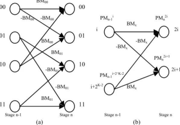
-BM00 BM00 -BM01 BM01 -BM01 BM01 -BM00 BM00 Stage n Stage n-1 00 00 PMn2i+1 PMn-1i+2^K-2 BMx -BMx -BMx BMx i+2K-2 i PMn-1i PMn2i 2i 01 01 10 10 2i+1 11 11 Stage n-1 Stage n (a) (b)
Figure 1 – Trellis diagram and a butterfly Since the computational complexity of the Viterbi decoder increases with the constraint length (K) of convolutional codes, a suitable architecture for the design has to be chosen.
To reduce the computational complexity in our design, the branch metrics are computed using Manhattan distance cost metric calculations [2]. Given Y0 and Y1 the decoder input symbols at stage n, the Manhattan distance cost of branch metrics are;
BM00 = Y0 + Y1; BM01 = Y0 – Y1
BM10 = – Y0 + Y1 = – BM01 ;
BM11 = –Y0 – Y1 = – BM00
Therefore, a single branch metric can be used to compute both the updated path metrics at any trellis node, as shown in figure 1 (a).
Symmetry in the Trellis diagram can be used to reduce the number of path metric calculations. A butterfly structure shown in figure 1 (b) is realized in our design. Each butterfly transforms to trellis nodes 2i and 2i+1 of stage n, from nodes i and i+2K-2 of stage n-1, as
depicted in figure 1 (b). Although there are four trellis paths coming from stage n-1 to stage n (two for each node), only one branch metric is needed to process the whole butterfly.
The minimum of the two incoming paths is selected at each node using following operations;
PMn2i = min { PMn-1i + BMx , PMn-1i+2^K-2 - BMx }
PMn2i+1 = min { PMn-1i – BMx , PMn-1i+2^K-2 + BMx }
Once N-stage computation is done, traceback operation is performed to extract N decoded bits. It is experimentally shown that the processing of 5xK stages (where K is constraint length) should be done to achieve trusted decoded bits before executing the traceback operation [3,4]. Therefore, the N is chosen to be 5xK in our design.
Since traceback is the reverse operation and as a result decoder generates decoded bits in inverse order, bit swapping is achieved by simply passing all the decoded bits through LIFO (Last-in-First-out) in our design.
III – Reconfigurable Viterbi decoder architecture
In our design, Viterbi decoder is composed of four functional blocks: Branch-metric unit (BMU), Add-compare-select unit (ACSU), Best-state unit (BSU) and Survivor-management unit (SMU). The functional block diagram of the reconfigurable Viterbi decoder architecture is shown in figure 2.
ACSU
BSU
Figure 2 – Reconfigurable Viterbi decoder
a) Branch metric Unit (BMU)
The branch metric unit computes Euclidean distance between the received convolutionally coded symbols and the ideally transmitted symbols. The received coded symbols can either be translated as hard bits or soft bits. Since to get the same error performance, soft bits require 2-3 dB less signal-to-noise power ratio than hard bits [4],
soft bits processing is chosen to be employed in our design. Thus the BMU accepts 3-bit symbol for each coded bit. It is known that this level is adequate to achieve practically the same performance as with un-quantized channel values [5, 6]. Moreover 8-level quantization causes a loss of less than 0.25dB in the signal-noise ratio compared to infinitely fine quantization [7], therefore, using more bits to represent a symbol is not very useful and we decided to work with 3-bit symbols.
The selection of the Viterbi decoder for the target wireless standards: 3GPP, GSM and 802.11a, is done using 2-bit input to the BMU. All the possible branch words are stored in the Lookup tables (LUTs). Upon selection of particular wireless standard, the concerned set of branch words are multiplexed out from the LUTs.
The branch metric are represented on 5-bits. The size of the branch metrics has strong relations with the path metrics size. Selection of larger path metrics would need larger memories for path metrics storage. The relationship between branch metrics and path metrics is depicted in the next part.
b) Add-Compare-Select Unit (ACSU)
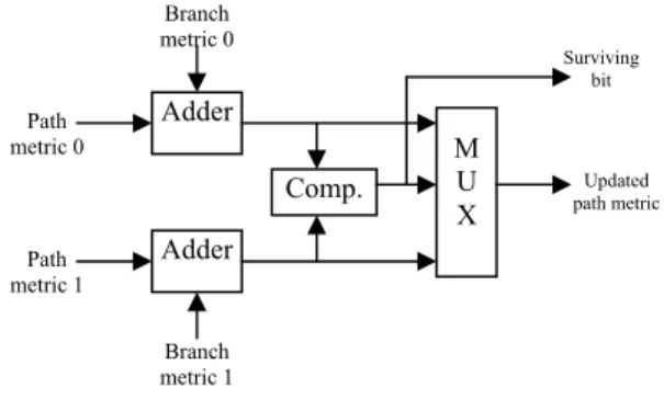
The ACSU takes in the branch metrics from the BMU and computes the path metrics and the survivor (decision) bits at each node in the trellis and stores the new (updated) path metrics in the path metric registers as input for the next stage. Each computed path metric and survivor bit represents an individual node in the trellis. This is done by adding the branch metrics with the node path metrics, comparing the two newly computed path metrics, and selecting the best path metric between the two. The best path also identifies the surviving path bit. The diagram of one ACS unit is shown in figure 3.
Adder Adder Comp. M U X Surviving bit Path metric 1 Path metric 0 Branch metric 1 Branch metric 0 Wireless standard selection Decoded bits Received coded symbols SMU BMU Updated path metric
Figure 3 – one ACS unit
The most demanding and complex part of the ACSU is its memory management for the updated path metrics. Since the updated path metrics are required in the processing of the next stage in the trellis, each and every path metric has to be stored at a particular position (using registers or RAMs) so that when the computation of the next stage starts correct path metrics can be called for the computation of the correct trellis nodes. In order to
achieve this, in-place update path metrics scheduling as proposed in [8] is employed.
The ACSU internal block diagram is shown in figure 4. The basic components of the ACSU are four PEs (containing 8 ACS processors; each PE contains 2 of the ACS units shown in figure 4), a RAM bank (containing 8 dual-port RAMs), a Shuffling Network and a Control unit.
Figure 4 – ACSU block diagram
In the ACSU architecture, processing elements (PEs) are the main processors which compute the updated path metrics. Each PE processes a butterfly in the trellis. The PEs receive branch metrics from the BMU and previous path metrics from the dual-port RAMs (the BMU inputs are not shown in the figure 4). Once updated path metrics by the PEs are computed, they are stored in the dual-port RAMs again after passing through the shuffle network. The choice of the RAMs where the updated path metrics are to be stored after computations is carefully designed, as we need these path metrics again for the processing of the next trellis stage. To keep things simple we always store the path metrics of the same states in the same RAMs. This is achieved by the shuffling network after the PEs that selects the path to the RAMs. For instance, while processing 256 nodes trellis (for K=9), dpram0 and dpram1 provide path metrics of nodes 0 and 128, respectively, to PE0. The PE0 computes updated path metrics for nodes 0 and 1 (in the trellis butterfly; ith and
i+2K-2 trellis nodes become 2i and 2i+1). The updated
path metrics of nodes 0 and 1 should be stored in the same RAMs where they were initially stored, so the shuffling network is switched in such a way that the updated path metric of node 0 goes to dpram0 and of node 1 goes to dpram4. Similarly, for the same trellis, if dpram2 and dpram3 provide path metrics of nodes 64 and 192, respectively, to PE1. The updated path metrics for node 128 and 129 are processed by PE1. The shuffle network directs the updated path metrics of the nodes 128 and 129 to dpram1 and dpram5, respectively.
Due to the fact that the path metrics are saved in a finite-length registers, normalization is required to deal with overflowing, as path metrics tend to grow while
computing trellis stages and get overflow. There are many path metric normalization techniques described in [9]. Modulo-normalization technique is employed in our design. This technique is based on the fact that the difference between all the path metrics at any trellis stage is kept bounded in magnitude by a fixed quantity independent of the number of ACS operations already performed in the trellis. To realize this, one has to follow the relation: A0 A1 SWT 9 9 9x8 dpram7 dpram5 dpram3 dpram1 dpram6 dpram4 dpram2 dpram0
* Branch metric inputs to and survivor bits output from the PEs are not shown.
Control Unit dpram7 dpram6 dpram5 dpram4 dpram3 dpram2 dpram1 dpram0 PE3 PE1 PE2 PE0 2c-1 – 1 > D max [i]
where c is the number of bits used to represent path metric and Dmax is the maximum difference between the
path metrics. Dmax is related to branch metrics as
Dmax = (BMmax – BMmin) (K – 1) [ii]
where BMmax and BMmin are maximum and minimum
branch metrics respectively and K is the constraint length. Using above relations, the path metric width in our design comes out to be 9-bits.
c) Best State Unit (BSU)
Since the traceback operation is started from the best state of the trellis, this unit compares all the path metrics of the trellis of 2K-1 nodes and identifies the best state. In
our design, the best state of the trellis is hunted while the ACSU is processing the final trellis stage, just before the beginning of the traceback operation. The traceback operation is initiated after the processing of 5xK trellis stages. For instance, with K=9, the traceback is initialized when ACSU processed 45 (=9x5) trellis stages. And the BSU operates while the 45th stage is
processed by the ACSU.
d) Survivor Management Unit (SMU)
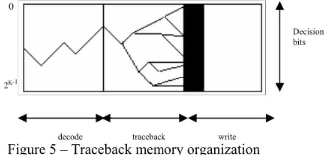
The SMU is responsible for finding the decoded data by using survivor bits computed by ACSU. Generally, there are two hardware approaches for survivor management, namely register exchange and traceback. We choose the traceback scheme over the register exchange because traceback is more suitable for reconfiguration purposes and because of the hardware cost of exchange registers for large trellis. In general, the survivor management unit organization of the traceback algorithm is shown in figure 5.
2K-1 0
Decision bits
Figure 5 – Traceback memory organization decode traceback write We use single dual-port RAM of size 3k x 8-bits. Dual-port RAM is selected in the design, to read and write the RAM in the same cycle. Thus the reading and
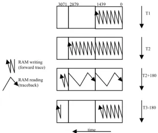
writing of the survivor bits is done simultaneously. In order to depict the operation of the traceback; let’s consider a trellis of 256 nodes (K=9). The operation of the RAM is illustrated in figure 6.
Figure 6 – The structure and operation of the traceback memory
First writing phase of the survivor bits into the RAM takes time T1. Second writing phase is completed in time T2 (T1 and T2 are equal). Once two writing phases are achieved, the traceback is triggered and takes 180 cycles to generate 45 decoded bits.
Since the decoded bits are obtained in reverse order, they are fed into the LIFO to swap their order.
IV – Results
The presented reconfigurable Viterbi decoder architecture is modeled in VHDL and simulated in ModelSim SE 5.8d.
It has been verified that after the initialization and early writing phases of the decoder, sequences of decoded bits are yielded. Each sequence contains 45 bits for K=9 and 35 bits for K=7. At the average one decoded bit is obtained after every 32 cycles for K=9 and after every 8 cycles for K=7. Hence, at a clock frequency of 100MHz a throughput of 3.125Mbps and 12.5Mbps is achieved for K=9 and K=7 respectively. Of course, depending on the target technology, higher frequencies could be reached, thus providing higher throughputs.
The fully validated Viterbi decoder is synthesized for Altera’s Stratix family (FPGA) device EP1S40F780C speed grade 5. The decoder core uses 1314 logic elements (3.2% of the total FPGA resources) and 35072 memory bits (1.04% of the total resources). Hence, as many as 31 Viterbi decoders could fit in the FPGA used.
Several reconfigurable Viterbi decoder implementations have been reported. In [10], a decoder for constraint lengths 3 to 7 and code rates 1/2 & 1/3 is presented. The throughput of 20Mbps is achieved with
this implementation. Unlike our design, this design realizes fully parallel scheme, where every trellis node is computed with a dedicated ACS unit. This approach results in large area and high power consumption. Utilization of over 89k logic gates is reported. Moreover, our design is targeted to the practical constraint length values and therefore, we choose to work around 7 and 9. No wireless standard is reported to choose constraint length 6 or other even number K values. Designing architecture for even number constraint lengths would probably be a waste of resources.
T3-180
T2+180 T2 T1 RAM reading (traceback) RAM writing (forward trace) 3071 2879 1439 0 time
Similarly, in [11] a Viterbi decoder design for K vales 3 to 9 and code rate 1/2 & 1/3 is reported. Throughput rates up to 60.5Mbps for Viterbi decoding and 3.54Mbps for Turbo decoding is shown. Fully parallel scheme is adopted and thus resulting in larger area and high power consumption. However, this design uses a power control unit to reduce the power consumption. The design requires over 190k logic gates and about 327k bits of memory. Compared with our architecture this cost is very high.
Another reconfigurable Viterbi decoder design is reported in [12], where an adaptive Viterbi decoding algorithm is used. Using this adaptive algorithm, instead of computing and retaining all the 2K-1 possible trellis
paths, only those paths which satisfy certain cost conditions are retained for each received symbol at each trellis node. Two implementations for K=4 to 9 and K=10 to 14 are reported in [12]. Both the implementations are based on fully parallel scheme, that is, large resource utilization and high power consumption. Moreover, very low throughput rates of the order of few hundred kbps are reported.
V – Conclusions
In this paper a reconfigurable Viterbi decoder architecture for Eurecom mobile platform is presented. The decoder can be reconfigured online for wireless standards 3GPP, GSM and WLAN 802.11a. The decoder is capable of to decode code rates 1/2 and 1/3. The generator polynomials for the target wireless standards; 3GPP, GSM and WLAN 802.11a; are fed into the decoder. In-place addressing scheme for updated path metrics as shown in [8] is adopted in the design. To make no effect on the processing speed of the decoder modulo normalization technique is implemented for path metric normalization. The best state unit (BSU) is introduced separately in the proposed architecture that features to find the best trellis state from all the computed states in all times. A single dual-port RAM is used for the trace-forward and traceback operations simultaneously. This choice leads to reduce significant amount of extra memory requirements. The presented reconfigurable Viterbi decoder has been successfully verified in simulations using ModelSim SE 5.8d and synthesized for Altera’s Stratix family (FPGA) device EP1S40F780C speed grade 5.
References
[1] G. D. Forney, Jr. “The Viterbi Algorithm”, Proceedings of The IEEE, vol. 61, pp. 268-278, Mar. 1978.
[2] Lou, H., “Viterbi decoder design for the IS-95 CDMA forward link”, Vehicular Technology Conference, 1996, “Mobile Technology for Human Race”, IEEE 46th, Vol. 2, Iss., 28 Apr-I May 1996,
1346-1350.
[3] B. Sklar. “Digital Communications-Fundamentals and Applications”, Prentice Hall, 2nd edition, 1988.
[4] Robert H. Morelos-Zaragoza, “The Art of Error Correcting Coding”, John Wiley & Sons Ltd.
[5] J. L. Massey, “Coding and Modulation in Digital Communications”, Proc. Int. Zurich Seminar on Dig. Comm., pp. E2(1)-E2(4), Zurich Switzerland, 1974.
[6] I. M. Onyszchuk, K.-M. Cheung and O. Collins, “Quantization Loss in Convolutional Decoding”, IEEE Trans. Comm., vol. 441, no. 2, pp. 261-265, Feb. 1993.
[7] I. Bogdan, M. Munteanu, P.A. Ivey, N.L. Seed, N. Powell, “Power Reduction Techniques for a Viterbi Decoder Implementation”, ESPLD 2000, Third
International Workshop July 25-28 2000 - Rapallo, Italy, ISBN 90-5326-036-6, pp 28-48.
[8] M. Biver, H. Kaeslin and C. Tommasini, “In-place updating of path metrics in Viterbi decoders ”IEEE Journal of Solid-State Circuits, vol. 24, no. 4, pp. 1158-1159, Aug 1989.
[9] C. Bernard Shung, Paul H. Siegel, Gottfried Ungerboeck, Hemant K. Thapar “VLSI Architectures for Metric Normalization in Viterbi Algorithm” IEEE 1990 1723-1728.
[10] K. Chadha, J. Cavallaro, “A Reconfigurable Viterbi Decoder Architecture”, Conference Record of the Asilomar Conference on Signals, Systems and Computers 1 , 66-71.
[11] J. Cavallaro, M. Vaya, “VITURBO: A Reconfigurable Architecture for Viterbi and Turbo Decoding”, ICASSP, IEEE International Conference on Acoustics, Speech and Signal Processing - Proceedings 2, 497-500.
[12] S. Swaminathan, R. Tessier, D. Goeckel, W. Burlesson, “A Dynamically Reconfigurable Adaptive Viterbi Decoder”, ACM/SIGDA International Symposium on Field Programmable Gate Arrays - FPGA, 227-236