HAL Id: hal-01622231
https://hal.archives-ouvertes.fr/hal-01622231
Submitted on 18 Apr 2018
HAL is a multi-disciplinary open access
archive for the deposit and dissemination of
sci-entific research documents, whether they are
pub-lished or not. The documents may come from
teaching and research institutions in France or
abroad, or from public or private research centers.
L’archive ouverte pluridisciplinaire HAL, est
destinée au dépôt et à la diffusion de documents
scientifiques de niveau recherche, publiés ou non,
émanant des établissements d’enseignement et de
recherche français ou étrangers, des laboratoires
publics ou privés.
Numerical and experimental investigations of Ti-6Al-4V
chip generation and thermo-mechanical couplings in
orthogonal cutting
Mahmoud Harzallah, Thomas Pottier, Johanna Senatore, Michel Mousseigne,
Guénaël Germain, Yann Landon
To cite this version:
Mahmoud Harzallah, Thomas Pottier, Johanna Senatore, Michel Mousseigne, Guénaël Germain, et
al.. Numerical and experimental investigations of Ti-6Al-4V chip generation and thermo-mechanical
couplings in orthogonal cutting. International Journal of Mechanical Sciences, Elsevier, 2017, 134,
p.189-202. �10.1016/j.ijmecsci.2017.10.017�. �hal-01622231�
Numerical
and
experimental
investigations
of
Ti-6Al-4V
chip
generation
and
thermo-mechanical
couplings
in
orthogonal
cutting
Mahmoud
Harzallah
a,∗,
Thomas
Pottier
a,
Johanna
Senatore
a,
Michel
Mousseigne
a,
Guénaël
Germain
b,
Yann
Landon
aa Université de Toulouse, CNRS, Mines Albi, INSA, UPS, ISAE-SUPAERO; ICA (Institut Clément Ader), Campus Jarlard, F-81013 Albi, France b Arts et Métiers ParisTech, LAMPA, 2 bd du Ronceray, 49035 Angers Cedex, France
a
b
s
t
r
a
c
t
ThechipformationmechanismoftheTi-6Al-4Vremainsachallengingprobleminthemachiningprocessas wellasitsmodelingandsimulation.StartingfromexperimentalobservationonthetitaniumalloysTi-6Al-4V machiningshowsthattheductilefractureinthechipformationisdominatedbytheshearphenomenonunder highstrainrateandtemperature,thepresentworkdevelopsanewcoupledbehavioranddamagemodelfor betterrepresentationandunderstandingofthechipformationprocess.ThebehavioranddamageofTi-6Al-4V havebeenstudiedviahat-shapedspecimenundertemperatureupto900°Candstrainrateupto1000s−1.An inverseidentificationmethodbasedonFiniteElement(FE)isestablishedinordertodeterminetheconstitutive law’sparameters.Thepredictionofthesegmentedchipwasanalyzedthrough3Dfiniteelementorthogonal cuttingmodelwhichwasvalidatedbyanin-situandpost-mortemorthogonalcuttingmachiningobservations. Finally,aparticularattentionisfocusedonthechipformationgenesiswhichisdescribedbythreesteps:Growth, GerminationandExtraction.
1. Introduction
Machiningisacommonprocessthatis widelyusedinthe manu-facturingofindustrialparts.Duringthecuttingprocess,thematerialis subjectedtolargestrainsathighstrainrateswhichinducetemperature increase(localheating)andachipremovalincomplexconditions.The predictionoftheprocessoutputs(machinedsurfaceintegrity,chip mor-phologyandcuttingforces)isanindustriallyandscientifically challeng-ingtask.Indeedthecouplednatureofthephenomenarequiressetting upvariousmodelsandofteninacoupledmanner.Moreover,the ex-tremevelocityandtemperatureresultinanadditionaldifficultyrelated tomodelsidentificationandvalidation.
Nowadays,thankstosignificantadvancesinsimulationtechniques, variousmethodsareusedtoenhancethequalityofsimulation predic-tions.Threemaintechniquesweresuccessfullyusedinpreviousstudies: FiniteElement (FE),SmoothedParticle Hydrodynamics,andDiscrete ElementMethods [1,2].Among thesetechniques, theFiniteElement Methodistheoldestandwassuccessfullyimplementedinvariousmetals formingprocesses.Itreliesonaspatialdiscretizationoftheconstitutive equationswhichmayinteractinacoupledmanner.
Thechipformationmechanismofmanyhardmetalsandespecially Ti-6Al-4V,resultsinthegenerationofserratedchips.Insuchcases,the
∗ Corresponding author at: Ecole des mines d’Albi-Carmaux, Allée des sciences, Campus Jarlard, 81013 Albi CT Cédex 09, France.
E-mail address: mahmoud.harzallah@mines-albi.fr (M. Harzallah).
nature ofthe thermomechanicalconditionsdrastically interlinksand thereforechallengestheexistingmodels.Manyresearchersaddressed comprehensiveandexhaustivestudiesonthephysicalphenomena in-volvedincuttingsuchmaterials(adiabaticshearband,crack propaga-tion)[3,4].
Inordertodescribethechipformationprocess,variouspublished papersaddressedconstitutivebehavioranddamagelawswhichprovide gooddescriptionsforawiderangeofmaterialsconcerningfinitestrain, strainrateandtemperature-dependentvisco-plasticity[5,6].The John-sonCookbehaviormodel[7]isamongtheselawsandisstillthemost popularphenomenologicalconstitutivelawadoptedtomodelthe mate-rialbehaviorduringthecuttingprocess[5,8,9].Calamaz[10]hasshown thatwithinatightrangeofstrainrateandtemperaturetheJohnson– Cookmodelisabletofitproperlymanymetalformingprocesses. Un-fortunately,outside ofthisrange,theflow stressisknownaspoorly extrapolated.
BasedonJohnsonCookapproach[7],variousresearchersmodified and/orextendedthemodeltodescribemoreaccuratelytheflow behav-ior.Thesepaperscanbesortedintofourgroups.
Thefirstgroupintended tomodify theviscosityeffectterm. This termwasthefirsttobe changedbyHolmquistandJohnson[11]to
improveitsimpactathighstrainratesbysubstitutingitwithasimple powerlaw.RuleandJones[12]modifiedthistermtobetterdescribe therapidincreaseofthestressaround103s−1inthecaseofcopperand
aluminumsamples.Finally,aquadraticformulationwasaddedtothis termbyWooJongKang[13]toenhancethestrainratesensitivityeffect forvarioussheetsteels.
ModificationsofthehardeningtermwereaddressedbyTanetal. [14]for7050-T7451alloyinuniaxialisothermaltensiletests.The au-thorsproposedarevisedJohnson–Cookmodelbyintroducinga cou-plingbetweenhardeningandstrainratethroughhardeningcoefficients. Basedonexperimentalobservations,Khanetal.[15]proposedan alter-nateformulationofthesamecouplingtodescribethequasi-staticand dynamicbehaviorinthecaseoftitaniumalloyTi-6Al-4V.By consider-ingastrongeffectofthethermalsofteningonthestrainhardening,a re-visedJohnson–CookmodelwasproposedbyVuralandCaro[16]which providedagoodcorrelationwiththeexperimentaldata.
Thethirdgroupfocusedonthethermalterm.InspiredfromJohnson– Cookmodel,severalformulationswereproposedbyLinetal.[17] con-sideringthecouplingeffectsbetween thestrain,strainrateand tem-peratureontheflowstress.Lietal.[18]proposedanewformulation whichconsidersthecouplingbetweenstrainandtemperatureathigh strainrateontheflowbehaviorinthecaseofahotcompressionofT24 steel.Formachiningprocess,Bäker [19]modifiedtheJohnson–Cook modelbyconsideringastrongcouplingbetweenthehardeningandthe thermalsofteningphenomenainordertodescribethedominanceofthis latterathightemperatures.Alossofductilitywasobservedby Sartkul-vanichetal.[20]inthecaseoftheAISI1045inatemperaturerange between200°C and400°C.TheauthorsmodifiedtheJohnson–Cook thermaltermbyaddinganexponentialformulationtoreproducethis effect.
Finally,many extensions of the Johnson–Cookflow stress model were proposed by the fourth group. The first extension was added throughamultiplicativetermbyAndradeetal.[21]todescribethe de-creaseofthestresscausedbythedynamicrecrystallizationinthecaseof coppercompressiontestsatastrainrateof10−3s−1.Toimprove
phys-icalunderstandingofthechipformationduringthecuttingprocess,an extensionknownasTanhtermwasproposedbyCalamazetal.[10]and usedbySimaandÖzel[22]inorder todescribethestrainsoftening phenomenoneffectsathightemperatureintitaniumalloys.
Inthepresentstudy,thefocusonserratedchipshasledtopaya spe-cialattentiontothedamagemodel.Indeed,materialseparationinsuch thermomechanicalconditionsinvolvescomplexphysicalmechanisms.
Becauseofthewidespread applicationsinvolvinglargeplastic de-formationsaccompaniedbyrapidincreaseoftemperatureanddamage evolution,manyworksweredevotedtoductilefracture.
McClintock [23]andalso Rice andTracey [24]proposed a the-orybasedonthegrowthofcylindricalandsphericalvoidsthemodel fracture.PorositybasedfracturetheoriessuchasdevelopedbyGurson [25]isanothermicrostructurebasedmodel.Ontheotherhand, phe-nomenologicalapproacheshavealsobeenproposedbyCockcroftand Latham[26]andmanyotherssincethen.
Mostofthesemodelsexhibitedahighdependencytothestress tri-axiality.Infact,basedonexperimentalobservations,manyresearchers showedthemajorimpactofthehydrostaticpressure.Usingroundbar specimens,Bridgman[27]wasthefirsttoanalyzethestrainfailure sen-sibilitytothehydrostaticpressureintheneckofspecimen.Under hy-drostaticloading,RiceandTracey[24]describedthegrowthofvoids andcavitiesbya simpleexponentialexpressionasafunctionof the stresstriaxiality𝜂.Especially,RiceandTracey’sexpressionbecamevery popularinthefractureapplicationandvariousresearchersextendedor modifiedthemodeltostudythedamageevolution.JohnsonandCook [28]extendedthisexpressionbyconsideringseparatelythestrainrate sensitivityandtemperaturedependency,whichallowedabroad applica-tionofthismodelinawidearrayofthermomechanicalprocesses[5,8]. However,theworkofWierzbickietal.[29]provedthatthe approxi-mationofthefailurestrainwithamonotonicallydecreasingfunctionof
stresstriaxialityispoor,whileastrongdependencytothethirdstress invariantistobepreferred.Wilkinsetal.[30]werethefirstto intro-duceseparatelythedeviatoricstressandtheLodeangleeffectsintheir damagemodel.AsanextensionofWilkins’modelandJohnson–Cook’s model,WierzbickiandXue[31]postulatedanewformulationby intro-ducingthedependencytothesetwovariables.
Itcanbementionedthatthedependencyintemperatureandstrain rateisnotexplicitlyaddressedinthemajorityofdamagemodels.By con-trast,itisimplicitlypresentedthroughtheirbehaviorlawasa thermo-visco-plasticevaluationofstress.
Thepresentpaperfirstly,proposedanddetailsanewformulation ofJohnsonCookmodelthroughitsLudwickhardeningterm.Its exper-imentalidentificationthroughhat-shapedcompressiontestsatvarious temperatureandstrainrateisthenpresented.Validationisperformed throughacomparisonwiththeJohnsonCookmodel.Secondly,a modi-fiedMaxsheardamagemodelanditscalibrationaredetailed.Then,by meansof3DFEorthogonalcuttingmodel,thechipformationprocess isinvestigatedandcomparedtoexperimentalobservations.Theselatter areperformedin-situ,duringthecuttingprocessandeitherathigh mag-nificationandhighframerate.Thechiplength,height,anglesand fre-quenciesareusedforcomparisonpurpose.Thecomparisontorecorded cuttingforcesisalsopresented.Finallyacomprehensivediscussionon thechipgenerationphenomenonisaddressed.
2. Flowruleandparameteridentification
2.1. Modeldescription
Themaingoaloftheproposedmodelingistopreventfromanalways controversialmodelselectionprocessbyassumingthesimplestmodel forhardeningnamelytheLudwik’slaw[32]whichisarestrictionof theJohnsonCookmodel.Thecouplinginstrain-rateandtemperature isthenpermittedthroughmaterialparameters.Theflowstressthus be-comes:
𝜎 =𝐴(̇𝜀,𝑇)+𝐵(̇𝜀,𝑇).𝜀𝑝𝑛(̇𝜀,𝑇) (1)
where𝐴(̇𝜀,𝑇), 𝐵(̇𝜀,𝑇)and𝑛(̇𝜀,𝑇)arerespectivelytheyield strength, thehardeningmodulusandthehardeningcoefficient.Theseparameters exhibitadependencyonboththestrainrateandtemperature.
2.2. Mechanicaltests
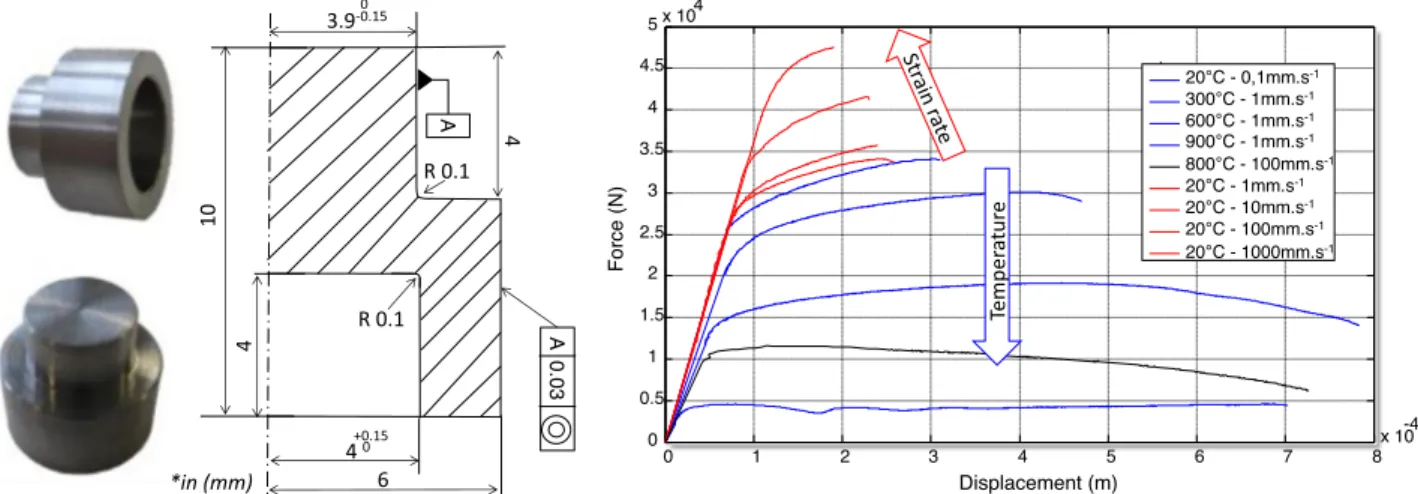
The parameter identificationis performed through nine dynamic tests using hat-shapedspecimenloaded in compressionbyaGleeble 3500testingmachine.Variousspeedandtemperatureareinvestigated, rangingfrom10−1mms−1to103mms−1andfrom20°Cto900°C
re-spectively. These tests wereperformedby Germain etal.[33]. Raw force/displacementcurvesareplottedinFig.1.
AsshowninFig.1,theforceisaffectedbybothtemperatureand strainrate(sincetheproportionalitybetweenthecrossheadspeedand strainrateisassumed).Asexpected,theforcedecreaseswith tempera-tureandincreaseswiththestrainrate.Particularly,asmalleffectofthe strainrateatambienttemperatureisobservedbetween10−1mms−1
and102mms−1.
2.3. Modelcalibrationprocedure
ThemainadvantageoftheformalismproposedinEq.(1)isthatit doesnotpresumeanyshapeforthecouplings,anduserscanfittheir experimentalpointsbyanysuitedanalyticalfunction.Thougha mini-mumofthreetestsarerequiredtofullycalibratetheproposedmodel, theexplicitnatureofthecouplingleadstoadirect relationbetween theidentificationqualityandtheamountofcalibrationtests,whereas itisnotnecessarilytrueiftheinterpolantshapeissetapriori(e.g.the Johnson–Cookmodel).
Fig. 1. (a) Hat-shaped specimen geometry (mm); (b) Experimental force–displacement curves of titanium alloy Ti-6Al-4V. First Set of parameters A0, B0,n0 Cost fonction Minimum ? New set of Parameters An, Bn, nn Simplex algorithm Final set of parameters A,B,n Boundaries
conditions Stress Field
RB Uy y x Rp Axis of Symmetry Ux = Urz =0 Ux=Uy = Urz =0
Heat transfert not allowed Imposed displacement Reference point Rigid Body RB Rp
Experimental Database
Yes No Fo rc e (N ) Experimental force Numerical force .inp Least-squares Method Numerical force Experimental force F(N) U (m)Cost function evaluation
Fig. 2. Iterative solving flowchart of the inverse problem. Moreover,theunivocalaspectofthecalibrationprocedureensures
thatasetoftestsleadstoaoneandonlyparameterset.Onthecontrary, inthecaseoftheJohnson–Cookmodel(anditsby-product)several pa-rametersetscanbeobtainedfromthesamemeasureddatadepending onwhichorderischosenfortheidentification(strain-ratetermfirstor temperaturetermfirst).
Thehat-shapedtestshavealreadybeenusedforanalytical identifica-tion[34].However,suchprocedurereliesonseveralcoarseassumptions suchas:(i)rectangularregionofinterest(ROI),(ii)rigidbodybehaviors outsideoftheROI,(iii)homogeneityofthestrainrateoverthematerial and(iv)stressuniaxiality.Thestrictnessofsuchhypothesisled vari-ousauthorslikeGermainetal.[33]toconsiderinverseidentificationin suchcasesandthesestudiesprovedthischoiceworthy.Inthepresent paper,finiteelementsupdate(FEU)isusedtoretrievematerial param-etersfromforce meansquarecomparisonandasimplexoptimization algorithm.MoredetailsontheFEUapproachcanbefoundinHarzallah
etal.[35].Thedifferentstepsofnumericalimplementationare summa-rizedinFig.2.
Anaxisymmetricfiniteelementhat-shapedmodelisdevelopedon ABAQUSExplicitplatform.Thesampleismeshedbyquadrilateral ax-isymmetricelements,coupledintemperature–displacementinreduced integrationcalculation(CAX4RT).Boththemovingandfixed compres-sionplatesaremodeledasanalyticalrigidbodieswhicharetiedtothe sample.
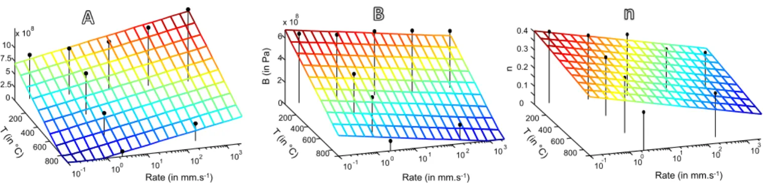
Theiterativesolvingprocedureleadstoasimultaneouslyoptimized parameterset(A,B,n)foreachoftheninetestsatvariousstrain-rates andtemperature.OnFig.3,theseidentifiedparametersareplottedas blackdots.
Theobtainedparametersetsallowtointroducethesuited analyt-ical description of the thermo-visco-plastic coupling. It can be seen from Fig.3that planefitting of theallthree parameters withinthe temperature-strain-ratespaceproperlyapproximatestheexperimental data.
200 400 600 800 10 -1 10 0 10 1 10 2 10 3 0 2.5 5 7.5 10 x 10 8 Rate (in mm.s-1) A (in Pa ) 200 400 600 800 10 -1 10 0 10 1 10 2 10 3 0 2 4 6 x 10 8 Rate (in mm.s-1) B (in Pa) 200 400 600 800 10 -1 10 0 10 1 10 2 10 3 0 0.1 0.2 0.3 0.4 Rate (in mm.s-1) n
Fig. 3. Modeling of the coupling for A, B and n. The best fit of each experimental response are plotted as black dots. Table 1
Identified flow rule parameters for Ti-6Al-4V.
A (Pa) B (Pa) n
a 9.36e + 005 5.57e + 05 9.46e − 05
b − 1.45e + 08 4.66e + 07 4.23e − 02
c − 8.65e + 08 − 6.39e + 08 − 0.365
Table 2
The identified Johnson–Cook parameters.
A (MPa) B (MPa) C n m 880 582 0.041 0.353 0.6337
Basedonthese observations,theevolutionoftheparametersasa functionoftemperatureandstrainrateisdescribedbyplanes.Foreach parameter,theplaneequationisexpressedas(Eq.2):
𝐴,𝐵,𝑛=−𝒂.𝑇−𝒃.log(̇𝜀)−𝒄 (2)
wherea,bandcaretheconstitutiveparametersofthelaw.Thesevalues arereportedinTable1.
2.4. ComparisonwiththeJohnson–Cookmodel
Inordertoassesstheimprovementbroughtbytheproposedmodel, acomparisonwiththeJohnson–Cookconstitutivelawisperformed.In fact,thislattermodeldescribestheflowstressofmaterialsasa multipli-cationofthreeterms:hardeningtermofLudwick[32],viscosity(strain rate)andthermaldependency(Eq.3).
𝜎 =[𝐴+𝐵(𝜀𝑝)𝑛][1+𝐶Log ( ̇𝜀 𝑝 ̇𝜀𝑝0 )][ 1−(𝑇−𝑇𝑟 𝑇𝑚−𝑇𝑟 )𝑚] (3) where𝜀𝑝,̇𝜀𝑝,̇𝜀𝑝0 arerespectivelytheplasticstrain,thestrainrateand
referenceplasticstrainrateandT,Tr,Tmarethetemperature,theroom
temperature,themeltingtemperatureoftheworkpiecematerial.A,B,C, m,narematerialparameterstobecalibrated.Forthistask,thesameFEU identificationprocedureappliedearlierfor𝐴(̇𝜀,𝑇),𝐵(̇𝜀,𝑇)and𝑛(̇𝜀,𝑇) andpresentedinFig.2,isusedagaintoidentifythe5parametersof theJohnsonCookatonce.ALevenberg–Marquardtalgorithm[36]was usedforasimultaneousidentificationofthesetofparameters(A,B,C, m,n) overthewholeexperimentaldatabaseatonce(i.e.the9tests). Thislatteralgorithmisprovenworthywhenthenumberofparameters becameconsequent[37].Inaddition,thequalityoptimalsolutionwas verifiedbycheckingthatthesameoptimumsetisreachedfromvarious initialsetofparameters.TheidentifiedJohnson–Cookparametersare mentionedinTable2.
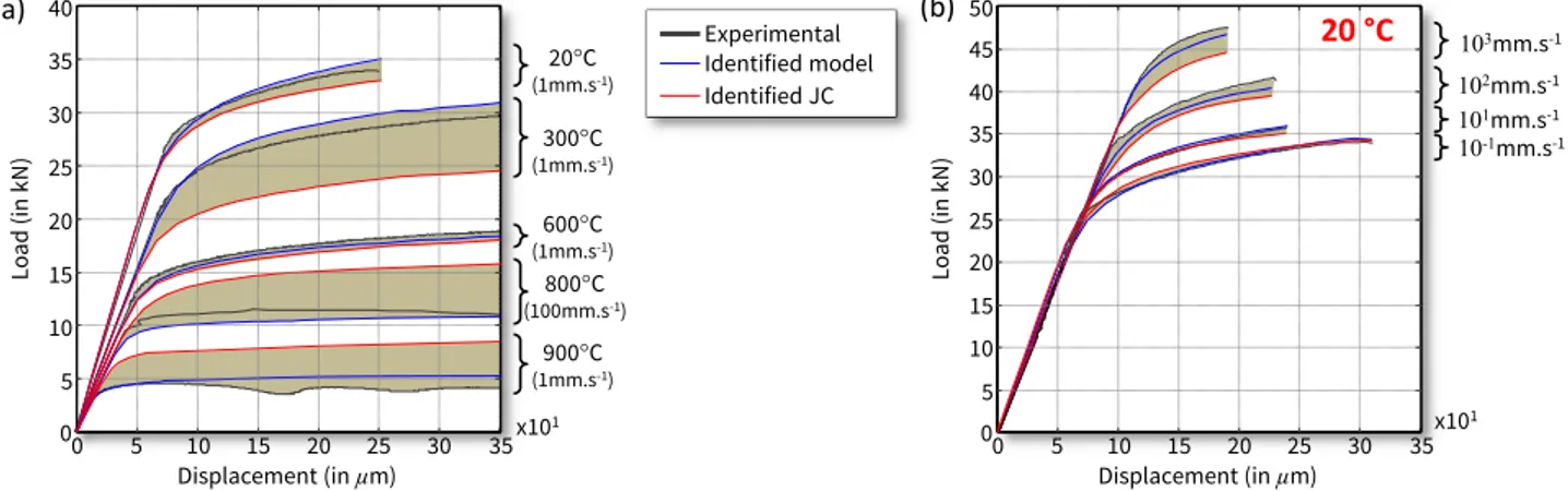
Theoptimumsetofparametersforthetwomodels(theproposed oneandJ-C)areusedinafiniteelementsimulationofeveryhat-shaped compressiontests.Thisallowsobtainingnumericalloadingforcesalong withthecorrespondingdisplacements.Bothmodelsarecomparedto experimentaldataforvarioustemperatureandstrainrate(Fig.4).
Itcanbeseenthatdespitetheplaneapproximation,theproposed modelproperlypredictstheexperimentaldataandgivesbetterresults thantheJohnson–Cookmodelunderallconditions.Becauseofthe con-stantparametersofthehardeningtermintheJohnson–Cooklaw,the shapeofthehardeningcurvesremainthesameoverallconditionsand suchhypothesisishereprovenquiteerroneous.
Atambienttemperature(20°C),theproposedmodelproperlyfits theexperimentalbehaviorwhiletheJohnson–Cookmodelshowsan ac-ceptableerror.Butwithinthewiderangeoftemperatureandstrainrate covered inthisapplication,theerrorincreasesasafunctionof these phenomenaforbothmodels.Neverthelessthemagnitudeofthiserror remainssmallerfortheproposedmodelthanfortheJCmodel.
3. Damagemodelimplementation
Aftercalibrationandvalidationoftheproposedbehaviorlaw,a par-ticularattentionispaidtothedamagemodelthroughthecoupling be-tweenphenomenainthechipformationprocess.
The experimental observations performed by Pottier et al. [38]provedthataductilefractureoccursduringthemachiningprocess thatis causedbyextensive plasticdeformationinducedbytheshear phenomenainthematerial.Fromamicromechanicalstandpoint,itis relatedtonucleation,growthandcoalescenceofvoidprovokedbythe increaseofthedensityofdislocationsunderhightemperatureandstrain rate.Fromaphenomenologicalstandpoint,theductilefractureis de-scribedasanaccumulationofplasticshearstraininducedbytheprocess. Thedamagemodelingclassicallyreliesonacumulativeformulationof thedamageinternalvariableD,ofwhichtheevolutionthroughout plas-ticityisdefinedby(Eq.4)
̇𝐷 =𝑑𝜀𝑝
̄𝜀𝑓 (4)
Suchformalismrequirestheassessmentofthestrainatfailure: ̄𝜀𝑓.
Variousrelationstothemechanicalfieldsweredevelopedforthis pur-pose.However,theshearnatureoftheloadingandthenarrowrange orstresstriaxialityinvolveincuttinghaveledtoconsidermaxshear failurecriterionassuitedforthisstudy.Thestrainrateandtemperature dependencyisthusbeingaddressedthroughthematerialparametersas proposedintheaboveforthehardeninglaw.
3.1. Themaximumshear(MS)damagecriterioninthespherical
coordinatesystem(̄𝜀𝑓,𝜂,𝜃)
Themaximumshear(orTresca)damagecriterioncanbeexpressed intermsofprincipalstressesbyEq.(5).
𝜎1−𝜎3=2𝜏𝑓 (5)
where𝜏f,istheonlyparametertocalibrateandstandsforthemaximum
Fig. 4. Comparison between experimental data, proposed model and Johnson–Cook model curves under: (a) Temperature (b) Strain rate. Fromgeometricalconsiderationthemaximumsheardamage
crite-rioncanbetransposedwithinthe(̄𝜀𝑓,𝜂,𝜃)spacefromEq.(6).
⎧ ⎪ ⎪ ⎨ ⎪ ⎪ ⎩ 𝑆1= 23̄𝜎 cos𝜃 𝑆2=23̄𝜎 cos( 2π3 −𝜃 ) 𝑆3=23̄𝜎 cos( 4π3 −𝜃 ) (6) wherē𝜎 isthesecondstressinvariant,𝜃 isthelodeangleandtheSiare
theprincipalcomponentofthestressdeviatortensor.Moredetailson thesetransformationscanbefoundinreferences[39,40].
Throughequations(6),anexpressionofthethreeprincipalstresses canstraight-forwardlybeobtainedasafunctionof ̄𝜎,𝜃 and𝜎mthefirst
invariantasfollows: ⎧ ⎪ ⎪ ⎨ ⎪ ⎪ ⎩ 𝜎1=𝜎𝑚+𝑆1=𝜎𝑚+23̄𝜎 cos𝜃 𝜎2=𝜎𝑚+𝑆2=𝜎𝑚+23̄𝜎 cos (2π 3 −𝜃 ) 𝜎3=𝜎𝑚+𝑆3=𝜎𝑚+23̄𝜎 cos (4π 3 −𝜃 ) (7)
Byintroducing theseexpressionsof 𝜎1and𝜎3 intothemaximum
shearcriterion(Eq.5),themodelcanbeexpressedasafunctionofthe normalizedlodeangleby(Eq.8):
̄𝜎 =𝜏𝑓 [ 1 √ 3𝑐𝑜𝑠 ( π 6−̄𝜃 )]−1 (8) With̄𝜃 =1−6𝜃∕𝜋.However,damagecriteriaareusuallydescribed andimplemented thoughtheequivalent strainatfailure𝜀𝑓.Forthat
purpose,Eq.(8)isusedtomodifythecoupledLudwick’sflowlaw pre-sentedintheabove.ThecoupledparametersA,B,andnidentified pre-viouslyarereusedtoenrichthedamagedescriptionanddependencyto bothtemperatureandstrain-rate.Themaximumsheardamagecriterion thereforeprovidesanexpressionoftheequivalentstrainatfailureasa functionofnotonly𝜃 and𝜏fbut alsoasfunctionofTand ̇𝜀suchas
(Eq.9): 𝜀𝑓= ⎡ ⎢ ⎢ ⎢ ⎣ √ 3𝜏𝑓 𝐵(̇𝜀,𝑇).cos(𝜋 ̄𝜃 6 ) −𝐴(̇𝜀,𝑇) 𝐵(̇𝜀,𝑇) ⎤ ⎥ ⎥ ⎥ ⎦ 1 𝑛(̇𝜀,𝑇) (9) However,BaiandWierzbicki[40]shownthatonlytheplanestress condition enable to relate between triaxiality and the Lode angle (Eq.10).
𝑐𝑜𝑠(3𝜃)=cos[𝜋2(1−̄𝜃)]=−272𝜂[𝜂2−13] (10)
Itcanbementionedthatonlyoneadditionalparameterneedstobe calibrated,namelythemaximumshearstressatfailure𝜏f.Itcanbe
iden-tifiedfromanykindoftestsofknownloadangle,throughtheprincipal
100 300 500 700 900 10-1 100 10 1 102 10 3 0 2 4 6 8 x 10⁸ Rate (in mm.s-1) (in P a)
Fig. 5. The 𝝉𝒇 ( ̇𝜺 , 𝑻 ) parameter identified evolution (black dots) and its least square plane
fit in the temperature/strain-rate space.
Table 3
The identified parameters of 𝜏f .
a b c
𝜏f 7.17.10 5 − 9.3.10 7 − 6.96.10 8
stressesatthepointoffractureandshouldalsodependonstrainrate andtemperature𝜏𝑓=𝜏𝑓(̇𝜀,𝑇)seereference[29].
3.2. MSdamagecriterioncalibration
AsrecommendedbyWierzbickietal.[29],thechoiceofsheartests with̄𝜃 =0easetheidentificationprocess.Forthatreason,experimental valuesoftheshearstressatfailureareobtainedfromthehat-shaped testspresentedabove.Inverseidentificationisperformedtoobtainthe stressfieldscorrespondingtotheglobaldisplacementobservedat fail-ure.Thestressfieldsareobtainedfromtheidentifiedflowmodel.
Theobtainedvaluesof𝜏𝑓(̇𝜀,𝑇)areshowninFig.5andthe
param-etersofthefittingleast-squareplanearesummarized inTable3. Ac-cordingly,thisparameterisdescribedasafunctionoftemperatureand strainratethroughEq.(2).
Theshapeof thefracturelocusispresentedinFig.6aforagiven temperatureandstrainrate.Thestrainatfailurevalue,whichusedfor calibration,isdeterminedfromtheoptimizedhat-shapednumerical sim-ulationunderthecorrespondingloadingconditions.Itcanbeseenthat directdependencytothestresstriaxialityratio𝜂 isnotshown,however thiscouplingisderivedfromthecouplednatureoftheloadangleand 𝜂.BymeansofEq.(10),thispointishighlightedinFig.6binthecase
Fig. 6. (a) Shape of the identified fracture locus in the ( ̄𝜺 𝒇 , 𝜼, 𝜽) space at T = 20 °C and a rate of 1 mm s −1 . (b) Restriction to the plane stress case. The calibration point is depicted as a
red star ( ɛ f = 0.213 ). (For interpretation of the references to color in this figure legend, the reader is referred to the web version of this article.).
ofplanestresshypothesis,wherethefracturelocusclearlydependson 𝜂.
Inaddition,asmentionedbyBaoandWierzbicki[41],forlow tri-axiality,the nature of metallurgicalphenomenon relatedtodamage changes,sothatcrackscannolongerpropagatesduetohigh compres-sivestressstate,whichleadstoexperimentalobservationswhere ma-terialisclearlyaffectedbut exhibitsnofailure.Forthispurpose,the valueof thestrainatfailureissetto10whentheloadingtriaxiality ratiodecreasesbelow𝜂sat=−1/3.
4. Chipformationsimulation
BythemeansofABAQUS/Explicitandusermaterialsubroutine VU-MAT,the damageandbehaviormodelsareimplemented intoa 3D-orthogonalcuttingFEmodel.
Inadditiontothesetwoconstitutivelaws,thesimulationofthechip formationprocessalsorequiresagoodcontrolanddescriptionofmany parameters:(i)partsgeometries,(ii)boundaryconditions,(iii)friction evolution.
4.1. Initialgeometry,meshesandboundaryconditions,andmaterial
properties
Thermomechanicalfieldsarecalculatedfromtheuseof3D contin-uumelementsunderreducedintegration(C3D8RT).Meshisrefinedin theregionofinterestinordertoenhancetheaccuracyatthetooltip. Thelowestmeshsizeinthemodelisabout25µmwhilethecoarsestis (200–500µm).
Thetungstencarbidetoolisconsideredasdeformableandmodeled byathermo-elasticlaw.Ithasanedgeradiusof20µm,aclearanceangle of11° andtworakeanglesaretestednamely−5°,15°.
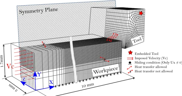
Thedimensionsoftheworkpieceare10mm inlength,1.5mmin width(w=3butaplaneofsymmetryisdefined)and1.7mminheight. Itismodeledbyasinglepartitiontoavoidmanymodelinghypotheses. Thatfavorsthechipseparationandhelpstobemorerealistic.
AssummarizedinFig.7,nodesonthebacksurfaceofthetoolare lockedover6dof.Thebottomsurfaceoftheworkpieceisonlyfreeto translatealongtheXaxis.Thedisplacementofthenodesontheback surfaceoftheworkpieceisimposedwithaconstantvelocitythatequals thedesiredcuttingspeed.
The3Dfinite elementmodelis setup undersymmetric condition (Fig.7)inordertoinvestigatetheevolutionofdamagemechanism ei-therunderplanestrainassumption(centerofthechipy=w/2)andplane stressassumption(sidefreesurfacey=0).
4.2. Contactandfrictionmodeling
Anotherimportantfeatureoffiniteelementbasedcomputationin cuttingsimulationisthefrictionlaw.Itisinfluencedbymanyfactors
suchasslidingvelocity,localcontactpressure,temperature,tooland workpiecematerialsasprovenbyBenAbdelalietal.[42].Duetoits simplicityanditsavailabilityinallFEcodessuchasAbaqus[43],the Coulombfrictionmodeliscommonlyusedforthisapplicationasdoneby Bäker[19].Extensivestudieswerecarriedoutatthetool/chipinterface byPulsetal.[44]whichareshownastrongmaterialadhesionatthe tooltipvicinity.Whenmovingalongtherakeface,aslidingmotionof thechipwasobserved.
Accordingly,astick-slipfrictionmodelwasdevelopedbyZorev[45]. Itadvocatestheexistenceoftwodistinctcontactregions(Fig.8): stick-ingcontactsaroundthetooltipwheretheshearstress𝜏f isassumedto
beequaltotheyieldshearstressofthematerial,𝜏y,whereas,inthe
slid-ingregion,thefrictionalstressislowerthantheyieldshearstress.Based intheseassumptions,aCoulomb–Trescamodelisadoptedtodefinethe tool–chipinterfacecontactwhichisdescribedasfollows(Eq.11): {
𝐼𝑓𝜏𝑓 <𝜏𝑦 𝑡ℎ𝑒𝑛𝜏𝑓 =𝜇.𝜎𝑛(Slidingregion)
𝐼𝑓𝜇.𝜎𝑛= 𝜏𝑦 𝑡ℎ𝑒𝑛𝜏𝑓 =𝜏𝑦 (Stickregion) (11)
where𝜎nisthenormalstressand𝜇 theCoulomb’sfrictioncoefficientis
heresetto0.2asproposedbyZhangetal.[46].
4.3. Materials,machiningparametersandcontactconditions
Thephysicalpropertiesofthetoolandtheworkpiece,aswellasthe contactconditionsarereportedinTable4,whereastheconstitutiveand damagemodelparametersarementionedaboveinTable1.
5. Resultsanddiscussion
Thepresentsectiondealswiththenumericalandexperimental re-sultsobtainedfromorthogonalcuttingoftitaniumalloyTi-6Al-4V.In ordertovalidatetheorthogonalcuttingmodeldevelopedinthepresent work, thenumericalresults arecomparedtoexperimental data.The evolutionsofthechipsizeandcuttingforcesarethusmonitoredand compared.Moreover,aparticularattentionispaidtothechip morphol-ogyintermsofsegmentationandthephysicalmechanismgoverningthe particularchipshapegeneration.
5.1. Finiteelementchipmorphologyresults
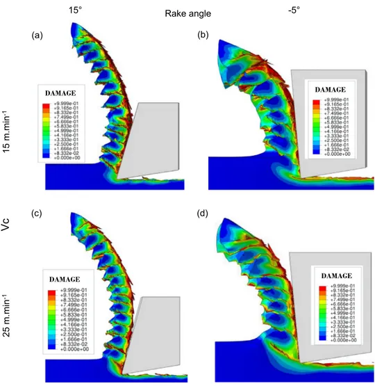
ThesimulationscarriedoutarepresentedinFig.9.Thedamage dis-tributioncorrespondingtomaterialdegradationduringthechip forma-tionprocessispresentedforfourmachiningconditionsintermsof cut-tingspeed(15and25mmin−1)andrakeangle(−5° and+15°).
Underallmachiningconditions, segmentedchipmorphologyand quasi-periodiccracksareobserved.Thematerialseparationinitiatesat thesidefreesurface,closetothetooltipandpropagateswithinthe mate-rial.Itcanbenoticedthatmostofthedamagephenomenonislocalized atthetool–chipinterface(secondaryshearzone)andintheshearband
Fig. 7. Orthogonal cutting model: geometries and boundaries conditions. Table 4
Material properties and contact condition. Material properties and contact conditions [5]
Materials properties Property Workpiece Tool Density 𝜌 (kg m −3 ) 4430 15,700
Elastic modulus E (GPa) 110 705 Poisson’s ratio ϑ 0.33 0.23 Specific heat C p (J kg −1 °C) 670 178 Thermal conductivity 𝜆 (W m −1 °C) 6.6 24
Expansion coefficient 𝛼expansion (µm m −1 °C) 9 5 Room temperature T room (°C) 20
Inelastic heat fraction 𝛽TQ 0.9 –
Contact Friction coefficient µ 0.2 Friction energy transformed to heat 99%
Fig. 8. Stick-slip contact Model.
(primaryshearzone).Thesegmentsmorphologyisgreatlyaffectedby therakeanglewhilethecuttingspeedseemsofleastinfluence.These observationsaretobeconfirmedbyexperimentalcomparisonandthis isthepointofthenextsection.
5.2. Experimentalsetup
Oneofmainimprovementofthisworkistheuseofhighspeed cam-eraequippedbyahighmagnificationopticsallowingtoaccessthe re-gionof cutandthereforetoobserveandanalyze thechipformation mechanisms.
Theorthogonalcuttingconfigurationisobtainedthroughaspecific testdevise(DEXTER)developedforthisapplication.Therelativespeed betweenthetoolandtheworkpieceisobtainedusingalinearaxiswhich allowsvaryingthecuttingvelocityupto120mmin−1.Theuncoated
carbidetools(rakeangles𝛾 =−5°;+15°)arefixedona6-components dynamometer(Kistler9257A)inordertomeasuretheforcecomponents foreachcuttingconfiguration.
Theworkpieceispolishedandetchedfor10sbykroll’sreagentto revealTi-6Al-4Vmicrostructure,thuspermittingabetteraccuracyinthe imageanalysis.Adepthofcutof0.25mmisselectedandtwocutting speedswereinvestigated(15and25mmin−1).
Theopticaldevice(Fig.10)consistsofaPhotronSA3camerawith CMOSsensor,coupledtoareflectiveSchwarzschildobjective (magnifi-cationX15).A120Whalogenlightguideisusedtoilluminatethescene. Theuseofhighspeedcamerarequiresacompromisebetweenframe rate,frameresolutionandthecuttingvelocityinordertoobtain accept-ableimages(unblurred).Consequently,theseparametersaremodified forthetestsashighlightedinTable5.Thesesettingsensureapixelsize of1.133µm/pixel.
5.3. Chipsmorphology
Alltheperformedcuttingtestsledtoserratedchips,generatedfrom periodiccrackspropagation(Fig.11).Itisalsofoundthatthechip mor-phologydifferswhetherpositiveornegativerakeanglesareused.
Itmustbementionedthatasignificanttransversal(outofplane) de-formationofthechipsurfaceisobservedforallcuttingconditions.As
Fig. 9. Numerical results under all machining parameters.
Fig. 10. Experimental setup.
Table 5
Machining and recording parameters.
Rake angle (°) Cutting velocity (m min −1 ) Frame rate (fps) Spatial resolution (pixels) Exposure time (µs)
Test 1 15 15 6000 512 × 512 5
Test 2 25 10,000 384 × 352 2.5
Test 3 − 5 15 6000 512 × 512 4
Table 6
Number of frames and segments for each test.
Test number Number of frames Number of measured segments Metric frequency of segmentation (segment/mm)
1 2113 306 2.49
2 1166 362 3.26
3 1761 161 2.15
4 2049 251 2.89
Fig. 11. Images captured at four cutting conditions and geometrical parametrization of
the chip morphology.
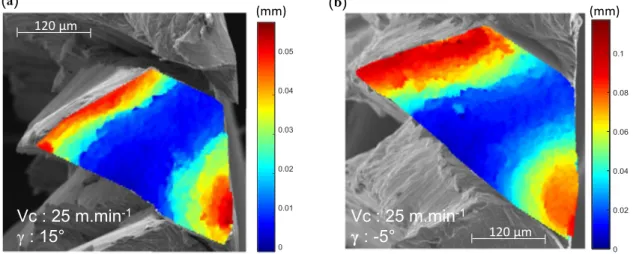
depictedinFig.12,furtheraltimetryinvestigationsbyextendedfield confocalmicroscopy(EFCM)showedthatthemagnitudeofthis defor-mationincreaseswithnegativerakeangles.Asignificantswellis ob-servedinthesecondaryshearzoneandmorespecificallyinthestick region(seeSection4.2).Anotherbulgeisobservedatopthesegment. Thiscorrespondstothetertiaryshearzoneofthepreviouscut.The mag-nitudeofthisdeformationdoubleswhentherakeanglerangesfrom15° to−5°.Thislatterfindingleadstoconsiderthatsuchanglesaffectmore deeplyandmoresignificantlythegeneratedsurface.Howeverfurther investigationsneedtobeconductedtobeconclusiveonthismatter.
Thankstofastimagingtechnique,theserratedchipmorphologycan beanalyzedmoreindetailsandcharacterizedbytheirlength(L)andthe shearangle(𝜑)asdefinedinFig.11.Theseparametersweremeasured foreachsegmentofeachtestinordertoinvestigatetheevolutionofthe chipshaperegardingtherakeangleandthecuttingvelocity.
Thewholecapturedsequenceforeachtestisdescribedbyitsnumber offramesandthecorrespondingnumberofsegments,assummarizedin Table6.
Toanalyzethechipsegmentationphenomenon,manyparameters aredefinedintheliterature,suchasthechipsegmentationfrequency (Hz)andthesegmentationintensity[47,48].However,theselatterare notabletoensurecomparisonwithothertestsunderdifferent machin-ingconditions.Consequently,inthepresentwork,thecharacterization ofthemetricfrequencyofsegmentation(insegmentpermillimeter)is preferred.
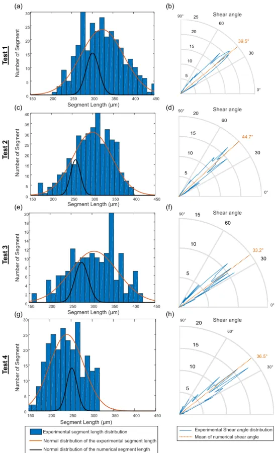
Asit can be seenin Table 6, themetricsegmentation frequency stronglydependsoncuttingconditions.Itincreaseswithboththe cut-tingspeedandtherakeangle.Thisparameterisdirectlylinkedtothe segmentlength,butmayalsobeinfluencedbytheshearangle.Fig.13 depictsthedistributionsandevolutionsofthesegmentslengthsandthe shearangles.
ItcanbeseenfromFig.13a,c,eandgthattheexperimentalsegment lengthdistributionsseemtobenormallydistributedandexhibitastrong dispersionforalltests.Bycomparingwithnumericalresults,the aver-agevalueofthesegmentlengthisrelativelywellsimulated.Withthe increaseofthecuttingspeed(tests2and4),thesegmentlengthbecomes slightlysmallerandconsequently,themetricfrequencyofsegmentation becomesmoreimportant(Table6).Moreover,withtheuseofanegative angle,thesegmentlengthisstronglyreduced.Moreprecisely,the stiff-nessdegradationintheprimaryshearzoneensuresthechipdeformation inadifferentwayastheshearplaneshapechanges.Withapositiverake angle(tests1and2),theshearsurfacecanbedescribedproperlybya simpleplaneinwhichangleismainlycomprisedbetween39° and45° (Fig.13bandd).Bycontrast,theuseofanegativerakeanglegivesbirth toanadditionalcompressioncomponentinthechipduringtheprocess whichinducedeformationintheshearplaneandconsequentlywiden
150 200 250 300 350 400 450 0 5 10 15 20 25 30 Shear angle
Te
st
1
Segment Length (µm)(a)
Number of S egment(b)
0° 90° 39.5° 150 200 250 300 350 400 450 0 5 10 15 20 25 30 35 40 Segment Length (µm)Te
st
2
Number of Segment Shear angle 90° 0° 150 200 250 300 350 400 450 0 2 4 6 8 10 12 14 16 18 20 Segment Length (µm)Te
st
3
Number of Segment 44.7° Shear angle 90° 0° 33.2° 150 200 250 300 350 400 450 0 5 10 15 20 25 30 Segment Length (µm)Te
st
4
Number of S egment 36.5° 90° 0° 30° 60°(c)
(d)
(e)
(f)
(g)
(h)
Shear angleExperimental segment length distribution
Normal distribution of the experimental segment length Normal distribution of the numerical segment length
Experimental Shear angle distribution Mean of numerical shear angle
Fig. 13. Segment length and shear angle distributions for each segment. thedispersionoftheshearanglemostlycomprisedbetween30° and45°
(Fig.13fandh).Theseexperimentalfindingsshowthedifferentnatures ofthemechanicalloadingsresponsibleforthematerialfailure inthe primaryshearzone.
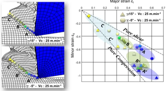
Fig.14showsthelastcomputedstateofstrainbeforematerialfailure formanypointsalongtheprimaryshearplane.
Itcanbeseenthattheloadingsthatleadtofailurediffersfromthe rakeanglechanges.Forapositive rakeangle,itisclearlyfoundthat shearisleadingmodeoffailure.However,acompressive/shear
defor-Fig. 14. State of strain at failure in the shear plane for − 5° and 15° rake angles.
Fig. 15. Experimental and numerical cutting forces comparison for all cutting condition. mationisobservedinthecaseofthenegativerakeangle.Nearbythetool
tip,thestateofthestrainisalmoststrictlycompressivewhilebymoving awayfromthetooltiptheshearphenomenonbecamemoreandmore significant.Multipleconclusionscanbedrawnfromtheseobservations andcomputations:first,theprimaryshearzonedoesnotonlywithstand shear.Second,thenatureofthemechanicalloadingishighlyrelatedto thecuttinggeometry(rakeangle)andthirdthestochasticnatureofthe observedsegmentshapesishardlypredictedbycomputationand fur-thermodelsexhibitingamoreprobabilisticnatureshouldbeaddedat somepoint.
Basedontheseobservations,itappearsthattheshearplaneismore hardlyaffectedbytherakeanglethanbythecuttingvelocity. Conse-quently,ittendstoprovethattheshearanglestaysmostlyageometric parameterandthusbringstolightseveralchallengesaboutthe influ-enceofthehydrostaticpressureontheshapeandgeometryoftheshear band.
Nevertheless,agreatdispersionisobservedinthechipparameters (shearangle,length)andinthechipshapethroughouttestswitha
nega-tiverakeangle.Thishighlightsthestochasticaspectofthecutting mech-anismsandindicatesthatthisaspectseemsmoreimportantfora nega-tiverakeangles.
Foralltests,itcan beseen thatthesimulatedresults presentthe sameorderofmagnitudethantheexperimentalvalues.Howeveritis verynoticeablethattheshapedistributionofthecomputedsegments doesnotexhibitthesamevariationthantheobservations.Thisissuemay havetwopossibleorigins:(i)thegeometricrestrictionintheLagrangian finiteelementmodel,(ii) thedeterministic natureof FiniteElements thoughnumericalinstabilitymayleadtosomekindofrandomness. 5.4. Cuttingforces
Simulatedcuttingforcesunderdifferentmachiningconditionsare presentedandcomparedtoexperimentaldata(Fig.15).Itcanbenoted thattheforceisaffectedbytherakeangleandthecuttingvelocity.It increasesbyvaryingtherakeangletoward negativevaluesorby de-creasingthecuttingvelocity.
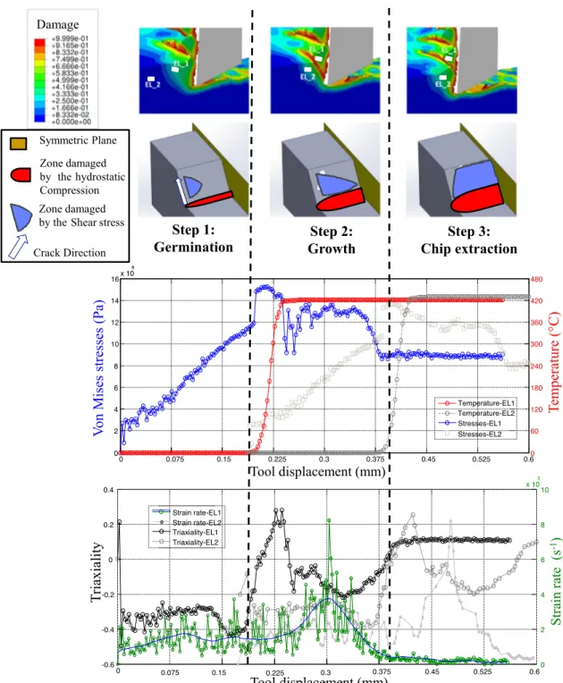
Fig. 16. Steps of the chip formation genesis (Vc: 25 m min −1 , rake angle: 15°).
Animportantvariation(upto500N)isobservedforthenumerical forces.Itcanbeexplainedbymanyreasonssuchastheelement dele-tionmethod,theassumptionof aconstantcuttingvelocity,themesh size.
Withapositiverakeangle,themeasuredcuttingforcesarecorrectly fittedbythenumericalones.Nerveless,theyareslightlyunderestimated forthenegativerakeangle.Itcanberelatedtothefrictioncoefficient whichisconstantoverallsimulations.
Insummary,itcanbesaidthatsimulationresultsshowagood agree-mentwithexperiments.Itpermitstopredictthechipformation mor-phologyandthecuttingforcesunderanacceptableerror.
5.5. Chipformationmechanisms
Theuse of areliable FiniteElement modelallowsimprovingthe understandingofserratedchipgenerationprocess.Moreespecially,a specificattentionisherepaidtothechipformationmechanisms.The numericalresultspresentedinFig.16leadtosplitthechipgeneration processintothreesuccessivesteps.This descriptionisbackedbythe experimental observationpresentedbyPottieretal.[38]whichalso proposedtoconsiderthreedifferentsub-processesthatleadtoserrated chips.Indeed,Fig.16promptstheevolutionofequivalentvonMises stresses,temperature,strainrateandtriaxialityratioduringthe forma-tionofasinglesegment.Thethreesuccessivesub-processesbeingthen:
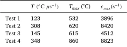
Table 7
The numerical evolution of the temperature and strain rate over tests.
̇𝑇 ( ◦C 𝜇s −1 ) T max (°C) ̇𝜀 𝑚𝑎𝑥 ( s −1 ) Test 1 123 532 3896 Test 2 308 620 8420 Test 3 145 615 4512 Test 4 348 860 8823
• Germination:duringthisphase,alinearevolutionofthevonMises
stressesisobservedduetoaconstantcompressiveloading(𝜂 ∼ −1∕3) fromthetooltip.Elasticenergyisstoredwithinthesegment(no ther-maldissipationisobserved)whileplasticitydevelopsintheprimary shearzone.Thisloadinginduces(i)anoutofplanedeformationof thechip(bulge)alsoclearlyvisibleonthevideos(seeSection4.3) and(ii)astronghydrostaticcompressivezoneatthetooltip.Theend ofthisstageisdefinedbytheuprisingofamicrocrackatthetool tip,i.e.thedamageparameterreachestheunityinthefirstelement whichisthusdeleted.
• Growth: it describes thecrack evolutionalong the primaryshear
plane. Itischaracterizedbyarapidincreaseofbothtemperature (300°C.µs−1)andstrainrate(upto700s−1).Becauseofhardening,
thevonMisesstrainremainsapproximatelyconstantwhilethermal dissipationismassive(Taylor–Quinneycoefficientsetto0.9).The triaxiality ratiopasseswithintherangeof [−0.1, 0.1]clearly in-dicatingthatshearisthedrivingmechanismsofthisphase.These coupledphenomenaactivate,firstlythestrainaccumulationinthe shear band(thatpushesthesegmentbackward)andsecondlythe crackpropagationalongthesamedirection.Thiscrackstartsatthe tooltipandevolveinsidetheshearzonetowardthefreechip sur-faceasdepictedinFig.16.Theendofthisstageissetasthecracks reachesthetopsurfaceandnofurtherstraincanbesummedupinto theshearband.
• Extraction: the von Mises stress decreases as thesegment moves
upward alongtherakeface andleaves theloadedzone. Temper-ature stabilizes as natural convective–radiative coolingstarts (in Fig.16temperatureremainsconstantinsteadofdecreasingbecause adiabaticboundaryconditionsareprescribed).Thedamage param-eter keepsincreasingatthetool/chipinterfaceleadingtoaslight increaseofthehydrostaticcompressivezone.Thefrictionuponthe nextsegmentleadstoaslightlypositivetriaxialityratiothatremains constantasthestrainratetendstowardzero.Thesegmentisthen fullyformed.
Foreachnumericaltest,anelementinthechip’ssegmentationzone waschosenandthen,theevolutionoftemperature ̇𝑇(◦Cμs−1),the
max-imaltemperatureTmax(°C)andthestrainrate ̇𝜀𝑚𝑎𝑥(s−1)arereported
inTable7.Despitetheevolutionofthemachiningconditions(cutting speedandrakeangle), itcan be underlined thatthechipformation mechanismsremainthesame.Themagnitudeofstrainrateand temper-aturesinvolvechangesbutthethreesamesub-processesareobserved.
Toimprovethephysicalcomprehensionofthechipformation, com-plementarychipSEMobservationswerecarriedout.AsshowninFig.17, amaterialcrackisobservedinthefreesideofthechipbutisnot ob-servedinthestresstriaxialityzone.FromtheobservationofFig.17bit canbeseenthataclassicalductilefractureisinvolve.Withanother mag-nificationfactor,itisobservedonthefracturesurfacethattheflow ma-terialtendstoconvergefromthesidetothecenterofthecut(Fig.17c). Theseobservationsareconsistentwiththenumericalresultspresented intheaboveandconfirmtheabilityoftheproposedmodeltopredict thespecifickindoffractureinvolveinsegmentedchipgeneration. Nev-ertheless,these evidencesof aductilefracturedonotallowtoclaim thepresenceorabsenceofso-calledadiabaticshearbandssuchas de-scribedbyRittelandWang[49].Itratherseemsthatbothphenomena areconsecutivetooneanother.
Fig. 17. SEM view of the chip (Vc: 25 m min −1 , rake angle 15°), B: detail view of crack,
C: detail of crack orientation. 6. Conclusions
ThisworkbringstolighttheTi-6Al-4Vchipformationproblem.The principalaimofthiscontributionisthecomprehensionandmodeling ofthephysicalphenomenainducingthesegmentedchipduringthe ma-chiningoftheTi-6Al-4Valloy.
BasedonJohnson–Cookmodel,anewbehaviormodelisproposedto ensureagooddescriptionofthetightcouplingbetweenthetemperature andthestrainrate.Thismodeliscalibratedbyaninverseidentification method throughdynamichat-shapedtests performedunderdifferent temperaturesupto900°Candstrainrates upto1000s−1.Thenew
behaviormodelproperlypredictstheexperimentaldataandgivesbetter resultsthantheJohnson–Cookmodelunderallmachiningconditions.
Sincethechipformationresultsfromplasticdeformationinduced bytheshearphenomena,themaxsheardamagecriterionwaschosen inthisstudytodescribetheductilefractureduringthechipformation. ItsLodeangledependencyanditscoupledstructuretobehaviormodel leadtobetterdescriptionofthedamagephenomenon.Inaddition,it requiresonlyonetestforcalibration.
A3Dorthogonalcuttingmodelissetupundersymmetric hypothe-sisinordertoexhibitthecapabilityofthemodelinrestitutingthechip formationmechanisms.Inaddition,tovalidatethisnumericalapproach, experimentalmachiningtestsusingaspecifictestbenchwereperformed andobservedbythemeanofahigh-speedcamera.Agoodagreement isobservedbetweenthenumericalandexperimentalresultsintermsof cuttingforcesandchipgeometries.Nevertheless,thepresented exper-imentalobservationleadstoconsiderthechipgenerationproblemas waymorestochasticthanpreviouslyconsideredintheliterature.This verymattershouldbeaddressedinfutureworks.
Basedonorthogonalcuttingsimulationresultsandexperimental in-vestigations,itappearsthatthechipformationprocessresultsfroma coupleddevelopmentofbothadiabaticshearbandandcrack propaga-tionwhichstartatthetooltipandevolveinsidetheshearzonetoward thefreesurface.Itcanbedescribedbythreesteps:Germination,Growth andExtraction.
Futureworkswillbefocusedonin-situthermalandstrainfield ob-servationthroughtheuseofhighspeedimagingandinfrared thermog-raphy,inordertoreinforcenumericalandtheexperimentalfindings.To improvetheabilityoftheproposedmodeltosimulatemoreaccurately thecuttingmechanisms,furtherworkhasalsotobedoneonthe devel-opmentofafrictionlawthatrepresentsmorefaithfullythephenomena thatoccursinthetool–chipinterfaceandthattakesintoaccountthe machiningparameters.
References
[1] Calamaz M, Limido J, Nouari M, Espinosa C, Coupard D, Salaün M, et al. Toward a better understanding of tool wear effect through a comparison between experiments and SPH numerical modelling of machining hard materials. Int J Refract Met Hard Mater 2009;27:595–604. doi: 10.1016/j.ijrmhm.2008.09.005 .
[2] Iliescu D, Gehin D, Iordanoff I, Girot F, Gutiérrez ME. A discrete element method for the simulation of CFRP cutting. Compos Sci Technol 2010;70:73–80. doi: 10.1016/j.compscitech.2009.09.007 .
[3] Komanduri R. Some clarifications on the mechanics of chip formation when machin- ing titanium alloys. Wear 1982;76:15–34. doi: 10.1016/0043-1648(82)90113-2 .
[4] Nakayama K , Arai M , Kanda T . Machining characteristics of hard materials. CIRP Ann - Manuf Technol 1988;37:89–92 doi:http://dx.doi.org/10.1016/S0007-8506(07)61592-3 .
[5] Ayed Y, Germain G, Ben Salem W, Hamdi H. Experimental and numerical study of laser-assisted machining of Ti6Al4V titanium alloy. Finite Elem Anal Des 2014;92:72–9. doi: 10.1016/j.finel.2014.08.006 .
[6] Liu J, Bai Y, Xu C. Evaluation of ductile fracture models in finite ele- ment simulation of metal cutting processes. J Manuf Sci Eng 2013;136:11010. doi: 10.1115/1.4025625 .
[7] Johnson GR , Cook WH . A constitutive model and data for metals subjected to large strains, high strain rates and high temperatures. In: Proceedings of the 7th Interna- tional Symposium on Ballistics, vol. 21; 1983. p. 541–7 .
[8] Mabrouki T, Courbon C, Zhang Y, Rech J, Nélias D, Asad M, et al. Some insights on the modelling of chip formation and its morphology during metal cutting operations. Comptes Rendus Mécanique 2016;344:335–54. doi: 10.1016/j.crme.2016.02.003 .
[9] Mabrouki T, Rigal J-F. A contribution to a qualitative understanding of thermo- mechanical effects during chip formation in hard turning. J Mater Process Technol 2006;176:214–21. doi: 10.1016/j.jmatprotec.2006.03.159 .
[10] Calamaz M, Coupard D, Girot F. A new material model for 2D numerical simulation of serrated chip formation when machining titanium alloy Ti–6Al–4V. Int J Mach Tools Manuf 2008;48:275–88. doi: 10.1016/j.ijmachtools.2007.10.014 .
[11] Holmquist T, Johnson R. Determination of constants and comparison for various constitutive models. J Phys 1991;4:853–60. doi: 10.1051/jp4:19913119 .
[12] RULE WK, Jones SE. A revised form for the Johnson–Cook strength model. Int J Impact Eng 1998;21:609–24. doi: 10.1016/S0734-743X(97)00081-X .
[13] Woo Jong Kang HH. Crash analysis of auto-body structures considering the strain- rate hardening effect. Seoul: 2000.
[14] Tan JQ, Zhan M, Liu S, Huang T, Guo J, Yang H. A modified Johnson–Cook model for tensile flow behaviors of 7050-T7451 aluminum alloy at high strain rates. Mater Sci Eng A 2015;631:214–19. doi: 10.1016/j.msea.2015.02.010 .
[15] Khan AS, Sung Suh Y, Kazmi R. Quasi-static and dynamic loading responses and constitutive modeling of titanium alloys. Int J Plast 2004;20:2233–48. doi: 10.1016/j.ijplas.2003.06.005 .
[16] Vural M, Caro J. Experimental analysis and constitutive modeling for the newly developed 2139-T8 alloy. Mater Sci Eng A 2009;520:56–65. doi: 10.1016/j.msea.2009.05.026 .
[17] Lin YC, Chen X-M, Liu G. A modified Johnson–Cook model for tensile be- haviors of typical high-strength alloy steel. Mater Sci Eng A 2010;527:6980–6. doi: 10.1016/j.msea.2010.07.061 .
[18] Li H, Wang X, Duan J, Liu J. A modified Johnson Cook model for elevated temperature flow behavior of T24 steel. Mater Sci Eng A 2013;577:138–46. doi: 10.1016/j.msea.2013.04.041 .
[19] Bäker M. Finite element simulation of high-speed cutting forces. J Mater Process Technol 2006;176:117–26. doi: 10.1016/j.jmatprotec.2006.02.019 .
[20] Sartkulvanich P, Koppka F, Altan T. Determination of flow stress for metal cut- ting simulation —a progress report. J Mater Process Technol 2004;146:61–71. doi: 10.1016/S0924-0136(03)00845-8 .
[21] Andrade UR, Meyers MA, Chokshi AH. Constitutive description of work- and shock-hardened copper. Scr Metall Mater 1994;30:933–8. doi: 10.1016/0956-716X(94)90418-9 .
[22] Sima M, Özel T. Modified material constitutive models for serrated chip formation simulations and experimental validation in machining of titanium alloy Ti–6Al–4V. Int J Mach Tools Manuf 2010;50:943–60. doi: 10.1016/j.ijmachtools.2010.08.004 .
[23] McClintock FA. A criterion for ductile fracture by the growth of holes. J Appl Mech 1968;35:363. doi: 10.1115/1.3601204 .
[24] Rice JR, Tracey DM. On the ductile enlargement of voids in triaxial stress fields ∗ . J Mech Phys Solids 1969;17:201–17. doi: 10.1016/0022-5096(69)90033-7 .
[25] Gurson AL. Continuum theory of ductile rupture by void nucleation and growth: part I —Yield criteria and flow rules for porous ductile media. J Eng Mater Technol 1977;99:2–15. doi: 10.1115/1.3443401 .
[26] Cockcroft MG , Latham DJ . Ductility and the workability of metals. J Inst Met 1968;96:33–9 .
[27] Bridgman PW. Studies in large plastic flow and fracture: with special emphasis on the effects of hydrostatic pressure. In: P.W. Bridgman (Ed.). New York-London: McGraw-Hill, 1952. 362 pp. $8.00. Science (80-) 1952;115:424. doi: 10.1126/sci- ence.115.2990.424 .
[28] Johnson GR, Cook WH. Fracture characteristics of three metals subjected to various strains, strain rates, temperatures and pressures. Eng Fract Mech 1985;21:31–48. doi: 10.1016/0013-7944(85)90052-9 .
[29] Wierzbicki T, Bao Y, Lee Y-W, Bai Y. Calibration and evaluation of seven fracture models. Int J Mech Sci 2005;47:719–43. doi: 10.1016/j.ijmecsci.2005.03.003 .
[30] Wilkins ML, Streit RD, Reaugh JE. Cumulative-strain-damage model of ductile frac- ture: simulation and prediction of engineering fracture tests. Lawrence Livermore Natl Lab CA (USA), Sci Appl Inc, San Leandro, CA, Tech Report, UCRL-53058 1980. [31] Wierzbicki T , Xue L . On the effect of the third invariant of the stress deviator on
ductile fracture; Impact Crashworthiness Lab Tech Rep; 2005 .
[32] Ludwik P. Elemente Der Technologischen Mechanik. Wien, Deutschland: 1909. doi: 10.1007/978-3-662-40293-1 .
[33] Germain G , Morel A , Braham-Bouchnak T . Identification of material constitutive laws representative of machining conditions for two titanium alloys: Ti6Al4V and Ti555-3. J Eng Mater Technol 2013;135:31002–11 .
[34] Hor A, Morel F, Lebrun J-L, Germain G. Modelling, identification and application of phenomenological constitutive laws over a large strain rate and temperature range. Mech Mater 2013;64:91–110. doi: 10.1016/j.mechmat.2013.05.002 .
[35] Harzallah M, Pottier T, Senatore J, Mousseigne M, Germain G, Landon Y. A new behavior model for better understanding of titanium alloys Ti-6Al-4V chip formation in orthogonal cutting. AIP Conf Proc, 1769; 2016. doi: 10.1063/1.4963490 .
[36] Marquardt DW. An algorithm for least-squares estimation of nonlinear parameters. J Soc Ind Appl Math 1963;11:431–41. doi: 10.1137/0111030 .
[37] Ponthot JP, Kleinermann JP. A cascade optimization methodology for au- tomatic parameter identification and shape/process optimization in metal forming simulation. Comput Methods Appl Mech Eng 2006;195:5472–508. doi: 10.1016/j.cma.2005.11.012 .
[38] Pottier T, Germain G, Calamaz M, Morel A, Coupard D. Sub-millimeter measure- ment of finite strains at cutting tool tip vicinity. Exp Mech 2014;54:1031–42. doi: 10.1007/s11340-014-9868-0 .
[39] Malvern LE. Introduction to the mechanics of a continuous medium. 1969. [40] Bai Y, Wierzbicki T. Application of extended Mohr-Coulomb criterion to ductile frac-
ture. Int J Fract 2010;161:1–20. doi: 10.1007/s10704-009-9422-8 .
[41] Bao Y, Wierzbicki T. On the cut-off value of negative triaxiality for fracture. Eng Fract Mech 2005;72:1049–69. doi: 10.1016/j.engfracmech.2004.07.011 .
[42] Ben Abdelali H, Claudin C, Rech J, Ben Salem W, Kapsa P, Dogui A. Exper- imental characterization of friction coefficient at the tool-chip-workpiece interface during dry cutting of AISI 1045. Wear 2012;286–287:108–15. doi: 10.1016/j.wear.2011.05.030 .
[43] Abaqus Abaqus Documentation 6.13, ; 2013 . http://129.97.46.200:2080/v6.13/
[44] Puls H, Klocke F, Lung D. Experimental investigation on friction under metal cutting conditions. Wear 2014;310:63–71. doi: 10.1016/j.wear.2013.12.020 .
[45] Zorev N . Interrelationship between shear processes occurring along tool face and on shear plane in metal cutting. In: ASME Proc Int Res Prod Eng. New York; 1963. p. 42–9 .
[46] Zhang Y, Outeiro JC, Mabrouki T. On the selection of Johnson–Cook constitutive model parameters for Ti-6Al-4V using three types of numerical models of orthogonal cutting. Proc CIRP 2015;31:112–17. doi: 10.1016/j.procir.2015.03.052 .
[47] Atlati S, Haddag B, Nouari M, Zenasni M. Analysis of a new segmen- tation intensity ratio “SIR ” to characterize the chip segmentation process in machining ductile metals. Int J Mach Tools Manuf 2011;51:687–700. doi: 10.1016/j.ijmachtools.2011.05.007 .
[48] Ducobu F, Rivière-Lorphèvre E, Filippi E. Numerical contribution to the comprehen- sion of saw-toothed Ti6Al4V chip formation in orthogonal cutting. Int J Mech Sci 2014;81:77–87. doi: 10.1016/j.ijmecsci.2014.02.017 .
[49] Rittel D, Wang ZG. Thermo-mechanical aspects of adiabatic shear failure of AM50 and Ti6Al4V alloys. Mech Mater 2008;40:629–35. doi: 10.1016/j.mechmat.2008.03.002 .