Publisher’s version / Version de l'éditeur:
Vous avez des questions? Nous pouvons vous aider. Pour communiquer directement avec un auteur, consultez la
première page de la revue dans laquelle son article a été publié afin de trouver ses coordonnées. Si vous n’arrivez
Questions? Contact the NRC Publications Archive team at
[email protected]. If you wish to email the authors directly, please see the first page of the publication for their contact information.
https://publications-cnrc.canada.ca/fra/droits
L’accès à ce site Web et l’utilisation de son contenu sont assujettis aux conditions présentées dans le site
LISEZ CES CONDITIONS ATTENTIVEMENT AVANT D’UTILISER CE SITE WEB.
Student Report (National Research Council of Canada. Institute for Ocean Technology); no. SR-2005-05, 2005
READ THESE TERMS AND CONDITIONS CAREFULLY BEFORE USING THIS WEBSITE. https://nrc-publications.canada.ca/eng/copyright
NRC Publications Archive Record / Notice des Archives des publications du CNRC :
https://nrc-publications.canada.ca/eng/view/object/?id=1a178439-6149-425f-815a-0a4bc86eeacd https://publications-cnrc.canada.ca/fra/voir/objet/?id=1a178439-6149-425f-815a-0a4bc86eeacd
NRC Publications Archive
Archives des publications du CNRC
For the publisher’s version, please access the DOI link below./ Pour consulter la version de l’éditeur, utilisez le lien DOI ci-dessous.
https://doi.org/10.4224/8895841
Access and use of this website and the material on it are subject to the Terms and Conditions set forth at PMM refurbishment plan
DOCUMENTATION PAGE
REPORT NUMBER
SR-2005-05
NRC REPORT NUMBER DATE
April 2005
REPORT SECURITY CLASSIFICATION
Unclassified DISTRIBUTION Unlimited TITLE PMM REFURBISHMENT PLAN AUTHOR(S) Mark Dawe
CORPORATE AUTHOR(S)/PERFORMING AGENCY(S)
Institute for Ocean Technology
PUBLICATION
SPONSORING AGENCY(S)
IOT PROJECT NUMBER
42_2079_10
NRC FILE NUMBER KEY WORDS
PMM, Planar Motion Mechanism
PAGES 29 FIGS. 14 TABLES 2 SUMMARY
This report describes the development of a 3-stage plan for refurbishment of the planar motion mechanism (PMM). The purpose behind refurbishing the PMM is to make improvements that will translate into more accurate test results. This report looks at increasing the PMM structural stiffness by replacing the yaw
mechanism, designing and building a new modular dynamometer for use on the PMM, and the issues associated with the current software for the PMM as well as possible improvements to be made in replacement software. Stage 1 of the refurbishment involves the design of the dynamometer. A cruciform structure was used as it showed greater stiffness then the present trapezoidal structure in finite element analysis. Other improvements made to the dynamometer include the use of button load cells as opposed to cantilever for increased stiffness. Stage 2 involves incorporating two tapered roller bearings into the yaw mechanism of the PMM. One bearing has a particularly large diameter that sits between the dynamometer and the PMM frame. This increases the stiffness of the PMM by allowing the dynamometer to be held closer to the PMM frame and through a wider contact surface. In stage 3 of the refurbishment issue with the current control software are addressed. The most important of these issues is the lack of documentation for the software. It is felt that rewriting the software would be the best solution. Stage 3 also lists some possible improvements that can be made to rewritten software such as the separation of the software into two entirely separate programs instead of having one program with two parts, as is the present case. Also, the future expansion of the PMM is considered in the software improvements by having excess control channels programmed into the software that would allow additional hardware controllers to be used.
ADDRESS National Research Council
Institute for Ocean Technology Arctic Avenue, P. O. Box 12093 St. John's, NL A1B 3T5
National Research Council Conseil national de recherches Canada Canada Institute for Ocean Institut des technologies Technology océaniques
PMM REFURBISHMENT PLAN
SR-2005-05Mark Dawe
TABLE OF CONTENTS Page List of Tables iv List of Figure v Summary vi 1.0 INTRODUCTION 1
2.0 STAGE 1: NEW DYNAMOMETER 2 2.1 New Dynamometer Development 2 2.2 New Dynamometer Details 8 2.3 Comparison of Old and New Dynamometers 11 3.0 STAGE 2: YAW MECHANISM MODIFICATIONS 12 3.1 Present Yaw Mechanism 13 3.2 Yaw System Refurbishment 14 4.0 STAGE 3: PMM SOFTWARE 21 4.1 Required Tests 21
4.2 Current Software Concerns 23 4.3 PMM Software Operation 24 4.4 Possible Software Improvements 26 5.0 CONCLUSION AND RECOMMENDATIONS 27
LIST OF TABLES
Page Results of Cruciform Live Frame vs Present Live Frame 7 New vs Present Full Dynamometer Comparison 12
LIST OF FIGURES
Page Figure 1: Original Dynamometer Live Frame Wire Model 3 Figure 2: Original Dynamometer Wire Model 4 Figure 3: New Dynamometer Live Frame Wire Model 6 Figure 4: New Dynamometer Wire Model 6 Figure 5: New Dynamometer Vertical Flexible Link Mount 8 Figure 6: New Dynamometer Horizontal Flexible Link Mount 10 Figure 7: New Dynamometer 11 Figure 8: PMM Inner Frame 13 Figure 9:PMM Inner Frame with Main Yaw Gear and Shaft 14 Figure 10: PMM Sway Frame 15 Figure 11: PMM w/ New Yaw System 16 Figure 12: Dynamometer Frame and Yaw Shaft 17 Figure 13: Refurbished Inner Frame 18 Figure 14: Exploded View of Dynamometer to Shaft Connection 19
SUMMARY
This report describes the development of a 3-stage plan for refurbishment of the planar motion mechanism (PMM). The purpose behind refurbishing the PMM is to make improvements that will translate into more accurate test results. This report looks at increasing the PMM structural stiffness by replacing the yaw mechanism, designing and building a new modular dynamometer for use on the PMM, and the issues associated with the current software for the PMM as well as possible improvements to be made in replacement software.
The first stage of PMM refurbishment looked at building a new dynamometer for use on the refurbished PMM. Finite element analysis was used to create a cruciform structure that was shown to be significantly stiffer under the six standard loadings (heave force, sway force, drag force, yaw moment, pitch moment, and roll moment). The new cruciform dynamometer is to be constructed using 4.5” schedule 40 aluminum pipe for the live frame and 3.5” schedule 40 steel pipe for the ground frame. Button load cells were also used to increase the stiffness of the dynamometer.
Stage two of the PMM refurbishment would involve stiffening the structure of the PMM itself by replacing the yaw mechanism. A 6” hollow shaft with threaded top will replace the current 4” hollow shaft requiring that the inner PMM frame be widened. A large nut will be screwed onto the shaft to hold it in place. Two tapered roller bearings will also be used to increase stiffness. One bearing will be approximately 27” in diameter and will sit between the dynamometer and the PMM frame. The second bearing will be around 8” in
diameter. It will sit between the top of the PMM frame and the large nut. This will allow the PMM frame to be compressed between the dynamometer and the nut.
The final stage of PMM refurbishment involves replacing the current PMM software. In general there is not a lot of confidence associated with the PMM software as a result of a lack of detailed documentation and a lack of understanding as to how the program functions. There are several options to improve the software. First of all the software could be separated into two separate programs, one for motion control and one for motion generation. The motion control software could include extra channels to allow for future expansion of the PMM and the motion control software could be used as a basis for other projects requiring motion control.
As a result of these modifications, the PMM will become a more reliable piece of testing equipment. In addition, allowing for the potential expansion of the PMM would be a benefit to IOT. Overall, increasing the structural stiffness of the PMM and dynamometer will allow for more accurate test results and ensure future use for the PMM.
1.0 INTRODUCTION
The planar motion mechanism, or PMM as referred to in this report, is a piece of testing equipment at IOT, which enables the simulation of real-world maneuvers in the testing tanks. The PMM adds two additional axes to testing. The standard test carriages provide forward motion along the x-axis. The PMM adds the ability to move the attached model perpendicular to the test carriage motion along the y-axis (sway), and allows the model to be rotated about the z-axis (yaw).
A refurbishment plan for the PMM would involve three separate stages. Stage 1 of the refurbishment would look at the dynamometer frame of the PMM. Through finite element analysis a new dynamometer would be designed and built for the PMM. This new dynamometer would be structurally stiffer then the present and would be modular to allow for changes in its setup.
The next stage of the refurbishment involves stiffening the sway carriage of the PMM by replacing the current yaw system. Increasing the stiffness of the yaw system would be beneficial to testing by providing a stiff background for the load cells to work against. This new yaw system will fit into the present device with as little modifications as
possible in addition to reusing some of the components of the present system to minimize costs.
The final stage of the refurbishment would look at the software of the PMM. The main concern with present software for the PMM is the lack of documentation present on the subject. The second phase of refurbishment would involve the design and creation of
new motion generation and motion control software. These new programs with sufficient documentation would make the PMM a more reliable piece of equipment.
2.0 STAGE 1: NEW DYNAMOMETER
Stage 1 of the PMM refurbishment would focus on the construction of a new
dynamometer. The main reason for building a new dynamometer is to improve testing accuracy by increasing the structural stiffness of the dynamometer. This third stage of refurbishment could also be expanded to include the development of specialized dynamometers. For example, dynamometers could be designed specifically for a particular model or category of models and easily installed or removed from the PMM.
2.1 New Dynamometer Development
From previous finite element analysis done on the PMM, one problem with the present dynamometer frame is that it is weak in torsion. This weakness mainly applies to the lower aluminum frame, but is inherent in the design of both the upper and lower frames. As a result the frame can be deflected out of the measuring plane and thus lead to less accurate results
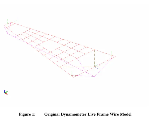
In order to get a basic idea of how the present dynamometer behaves under various loading conditions, two separate wire models were drawn in CadKey for use in Algor. The first model is of the lower / live frame of the present dynamometer. The frame is constructed from aluminum channel and the model was used mainly to determine a new shape for a dynamometer that offered better performance then the present. Figure 1,
below, shows the wire model of the live frame of the present PMM dynamometer. In this figure, the red lines are used to represent the structure of the live frame. The long purple line is representative of a vessel model and the other purple lines are the connections used between the vessel model and live dynamometer frame. The small green lines represent flexible links. Other lines would be used to model load cells and other components of the frame.
Figure 1: Original Dynamometer Live Frame Wire Model
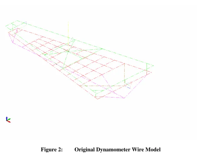
The second model (Figure 2) was a full wire model of the present dynamometer. This model was used to get an idea about the overall behavior of the structure under the same loading conditions as the previous model. The structure represented in Figure 1 can be seen in Figure 2 as well. The green lines in this case also represent the upper
dynamometer frame and the yellow line in the center represents the mounting tube of the dynamometer.
Figure 2: Original Dynamometer Wire Model
For the purpose of finite element analysis, all of the models were subjected to the same loadings so that all results could be compared. All loadings were applied to the long purple line in the models (vessel model representation). There were 6 separate loading cases that were applied to the models: 1) Drag Force, 2) Sway Force, 3) Heave Force, 4) Pitch Moment, 5) Yaw Moment, and 6) Roll Moment. The first three loadings were all applied forces. The magnitude of each was 100 lbf. These loads were applied in two different ways. For the drag load, a nodal force of 100 lbf was applied to the forward
node of the vessel (forward node of the long purple line) in the negative x-direction. For the sway and heave loadings, a distributed load was applied to the vessel with a
magnitude of 1.25 lbf/in in the positive y and z-directions respectively. Since the model is approximately 80 inches in length, this gives an applied load of 100 lbf. The last three cases were applied moments. All three were applied on both the forward and aft nodes of the vessel and all three had a magnitude of 1000 ft-lb (500 ft-lb per node). The pitch moment was applied about the y-axis, the yaw moment was applied about the z-axis, and the roll moment was applied about the x-axis.
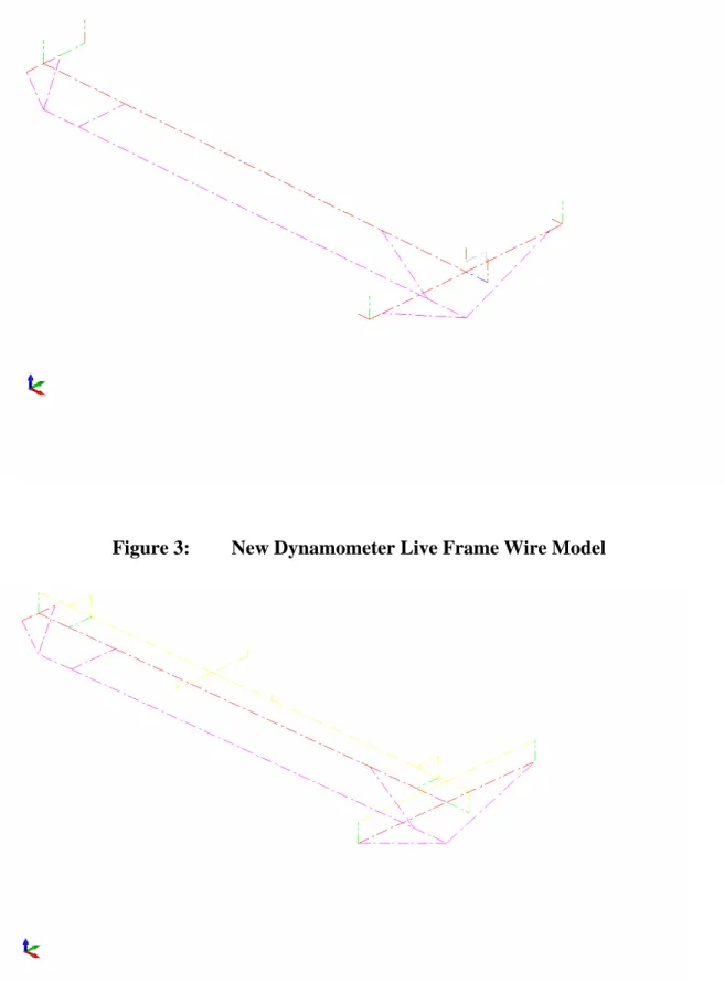
A new dynamometer was designed on the basis of improving the finite element analysis results of the present dynamometer. The new dynamometer has a double cruciform shape with the live frame constructed from 4.5” schedule 40 aluminum pipe and the upper frame constructed from 3.5” schedule 40 steel pipe. See Figure 3 for the live frame wire model and Figure 4 for the full wire model of the new dynamometer. The colour scheme for the lines in the wire models is the same as in Figures 1 and 2 above, with the
Figure 3: New Dynamometer Live Frame Wire Model
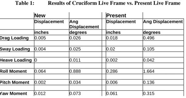
It was initially decided that the cruciform structure would be suitable for use in the new dynamometer by comparing the linear and angular deflections in the live frames of both designs. Table 1, below, shows the results of this initial analysis:
Table 1: Results of Cruciform Live Frame vs. Present Live Frame
New Present
Displacement Ang
Displacement
Displacement Ang Displacement
inches degrees inches degrees
Drag Loading 0.005 0.026 0.018 0.496 Sway Loading 0.004 0.025 0.02 0.105 Heave Loading 0 0.011 0.002 0.042 Roll Moment 0.064 0.888 0.286 1.664 Pitch Moment 0.002 0.034 0.006 0.136 Yaw Moment 0.012 0.073 0.061 0.315
It can be seen from the above table that the cruciform design results in a much stiffer structure. This is evident by the fact that both linear and angular deflections for the new live frame are much less then those of the present live frame.
In looking at these results and the analysis that produced them it is possible to make a prediction about the results for the full dynamometer. The deflections seen by the full dynamometer should be larger then the deflections seen by the live frame only. Part of this prediction goes back to the analysis where the upper ends of the flexible links were held fixed. When analyzing the full dynamometer, the upper end of the flexible links will no longer act against a fixed or infinitely rigid background, but will now act against a flexible background in the form of the ground frame. Since the ground frame is not
infinitely rigid, it will also deflect under the applied load, resulting in larger deflections. The new dynamometer, however, should experience lower overall total deflections when compared to the present. As a result the design of the new dynamometer proceeded on the grounds of the above results.
2.2 New Dynamometer Details
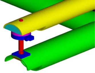
Using the cruciform shape, the new dynamometer was designed using button load cells as opposed to the cantilever load cells used on the present PMM. Button load cells have the advantage of increased stiffness over the cantilever style, which is what is needed to improve the stiffness of the dynamometer. Figure 5, below, shows the parts involved in mounting a flexible link. The button load cell is the circular dark blue part in the figure. The manufacturer of the load cell, Interface, provided the dimensional data for the Model 2400 Stainless Series Universal load cell used in the design.
Mounting the vertical flexible links on the live frame (green in Figure 5) requires two pads to be welded onto the frame. These pads are shown in dark blue and brown in Figure 5. The purpose of the pads is to provide a solid flat surface to mount the flexible link on. A 3/8” hole would be drilled through the two pads and the pipe wall once assembled so the flexible link could be bolted into place.
The backing for the load cell on the ground frame (yellow in Figure 5) consists of two parts. The first is a half cylinder section welded to the ground frame. Below the half cylinder is the base for the load cell. A 3/8” hole would be drilled through the pipe wall of the ground frame and the half cylinder section in order to attach the base / load cell. The base can be purchased from the maker of the button load cell and is recommended for use with it. The half cylinder section and load cell base can be seen in Figure 5 as the light blue and pink parts respectively. Sections are cut out of the live and ground frames to allow room for welding the pads into place and to provide space for mounting the parts.
This design, as described, will also provide modularity to the new dynamometer if desired. The Interface Model 2400 Stainless Series load cells are available in a range of capacities from 50 lbf to 5000 lbf. Specifically, the 2420 model load cells were used in the design. The 2420 model is available from 50 lbf to 1000 lbf. Therefore, the load cells could be interchanged for any capacity load cell in the 2420 model since this all load cells of this type have the same dimensions. The flexible links would also need to change to accommodate the desire load range, which is also possible.
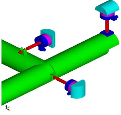
In the horizontal direction, the load cells are connected to the ground frame in the same manner as in the vertical direction. The connection between the flexible links and the live frame involves simple slots. The end of the flexible link fits into a slot and is then tightened into position. Figure 6, below, shows ¾ of the flexible link and load cell combinations on the forward live frame. Some parts described in Figure 5 can be seen here also. Of note in Figure 6 are the slots for the horizontal flexible links. In order to fit a slot into the live frame for the drag flexible link (center link in Figure 6), a section is removed from the frame and slot is welded in place.
Figure 6: New Dynamometer Horizontal Flexible Link Mount
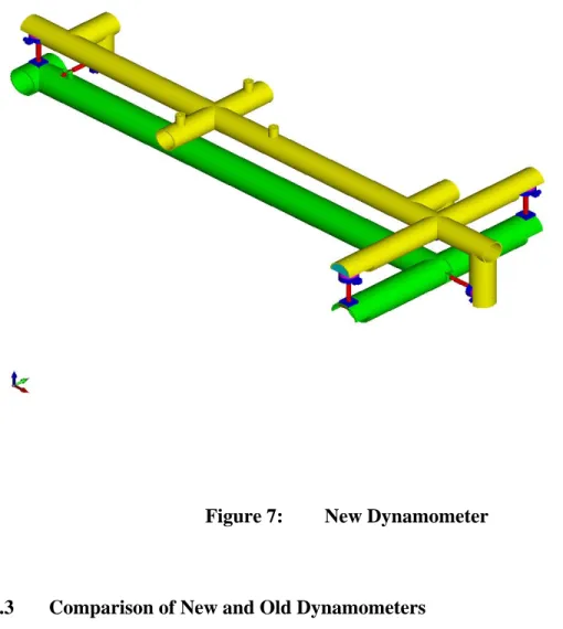
Figure 7 shows a full view of the new dynamometer. All of the details discussed can be seen in this figure. Also, in Figure 7, it is possible to see the three pegs in the center that are used to mount the dynamometer onto the new yaw system.
Figure 7: New Dynamometer
2.3 Comparison of New and Old Dynamometers
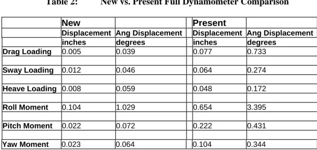
After the three-dimensional model of the new dynamometer was created using CadKey, it was then necessary to create a wire model representation so that the model could be analyzed in Algor. This wire model can be seen in Figure 4. It was compared using Algor to the wire model of the original PMM dynamometer seen in Figure 2. The loadings used for the full dynamometer comparison are described in section 2.1 on page 4. Table 2 presents the results of the analysis:
Table 2: New vs. Present Full Dynamometer Comparison
New Present
Displacement Ang Displacement Displacement Ang Displacement
inches degrees inches degrees
Drag Loading 0.005 0.039 0.077 0.733 Sway Loading 0.012 0.046 0.064 0.274 Heave Loading 0.008 0.059 0.048 0.172 Roll Moment 0.104 1.029 0.654 3.395 Pitch Moment 0.022 0.072 0.222 0.431 Yaw Moment 0.023 0.064 0.104 0.344
From the above results it is clear that the new dynamometer design outperforms the original design in almost every aspect. In some of the load situations there are drastic improvements in the new dynamometer design. This can be seen, for example, in the deflections caused by the applied roll moment. The new linear deflection of the new dynamometer was approximately 1/6 that of the old, and the angular displacement was reduced by almost 2.5 degrees.
3.0 STAGE 2: YAW MECHANISM MODIFICATIONS
Stage 2 of the PMM refurbishment would focus on the modifications to the yaw
mechanism of the present device. The goal is to stiffen the yaw mechanism by replacing the main yaw shaft with a stiffer version. There is an attempt in this stage to leave as much of the PMM unchanged to keep the cost of the refurbishment low. As a result, as many of the parts are reused where possible.
3.1 Present Yaw Mechanism
The PMM frame itself is made up of two main parts. The first is a square frame that allows the PMM frame to move in sway. This is called the sway carriage. The second is an inner frame that fits inside of the sway carriage. This inner frame is what actually supports the dynamometer and effectively grounds it by attaching to the sway carriage, which is itself connected to the test carriage by a set of rails.
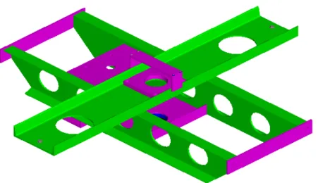
The following figure (Figure 8) is a representation of the inner frame of the PMM. This figure does not show any of the yaw mechanism.
Figure 8: PMM Inner Frame
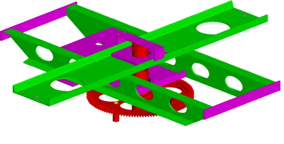
In Figure 9 (below), the inner frame is now shown with part of the yaw mechanism consisting of a pipe / shaft and the main yaw gear.
Figure 9: PMM Inner Frame with Main Yaw Gear and Shaft
3.2 Yaw System Refurbishment
The new yaw setup will replace the existing setup but would also keep as much of the frame untouched so as to remain compatible with the existing structure. The square sway carriage (Figure 10) sits on two rails that extend across the width of the testing tanks. A new yaw setup for the existing PMM would only require modifications to the inner frame and therefore would be easily replaced in the sway frame.
Figure 10: PMM Sway Frame
The main yaw gear shaft was made from a 4” steel pipe with approximately a ¾” wall thickness. In a finite element analysis with the full PMM sway carriage in isolation (i.e. the rails that the sway carriage sits on were not included), this setup is adequate for current testing needs. However, when an analysis of the entire system is performed (including rails), the 4” shaft is considered to be a weak point creating a relatively low natural frequency of 6.7 Hz and 7.2 Hz respectively in yaw and pitch. This result is greatly improved when the analysis used a 6” schedule 40 pipe instead of the 4” pipe. The natural frequency in yaw and pitch increased to 10.4 Hz and 11.2 Hz respectively
(Bell 2002). As a result, in the new yaw setup a 6” shaft will be used. Figure 11 below shows what the refitted PMM will look like with the present dynamometer.
Figure 11: PMM w/ New Yaw System
A big improvement to the structure of the yaw system is the addition of two tapered roller bearings. The lower tapered roller bearing measures 27” in diameter. This large
diameter bearing provides a contact surface between the dynamometer frame and the inner frame that will greatly help increase the stiffness of the setup. The profile of the PMM was also reduced by approximately 6.5” using this setup with the current
dynamometer. This is also a benefit, as it will help increase the stiffness of the structure by reducing the lengths of the moment arms that are acting on the carriage.
The connection method itself between the dynamometer frame and the inner frame of the PMM will also lend to an increase in stiffness. The shaft is attached via a connecting plate to the dynamometer frame. See figure 12 below for a view of the dynamometer frame with the shaft connected. The 27” tapered roller bearing rests against a plate on top of the dynamometer frame. This is held against the dynamometer frame by the connecting plate to which the large gear and shaft are also attached. All components shown in figure 5 are bolted together so that no one component can rotate by itself.
Figure 12: Dynamometer Frame and Yaw Shaft
The shaft then fits into the inner frame and is held there by a large nut which screws onto the shaft. In between the nut and the top of the inner frame is a second tapered roller bearing (9.75” diameter, 6.625” bore). When the shaft is inserted into the frame, there is
a steel ring that sits between the lower tapered roller bearing (23.5” bore) and the inner frame. This steel ring is the large blue ring that can be seen in Figure 13.
Figure 13: Refurbished Inner Frame
The new setup allows the dynamometer to be held into place using some level of
pretension that could vary depending on test conditions. The use of the two tapered roller bearings allow for the dynamometer frame to be rotated independently of the inner frame, as is presently the case while allowing the structure to be pretensioned. The
pretensioning will stiffen the structure by requiring any applied external moment to be great enough to first overcome the clamping force in the joint before causing any deflection of dynamometer frame with respect to the inner frame.
Another advantage to this new yaw system is it allows for easy detachment of the
Figure 14 shows an exploded view of the dynamometer frame and its connection with the shaft that will further illustrate this point.
Figure 14: Exploded View of Dynamometer to Shaft Connection
As seen in Figure 14, the plate that rests on top of the dynamometer frame is the light blue plate in the figure. On top of that rests the tapered roller bearing. The light purple connection plate sits in the middle and is bolted directly to the dynamometer frame. On top of the connection plate the main yaw gear bolts in place followed by the shaft.
This new yaw setup will require some changes to the inner frame of the PMM while keeping it similar to the original. First of all, the two green horizontal members shown in Figure 9 on page 14 must be widened by 8”. This is mainly to allow the large yaw gear to be brought further up into the frame to reduce the profile while allowing the gear to have sufficient space in which to operate. As a result of this, some of the pieces
connecting these two members must be replaced with ones 8” longer. The rest of these connecting pieces are removed from the structure because they are no longer needed. For example, both of the steel channels that held bearings to support the lower ends of both the large gear shaft and the drive shaft are no longer needed since both the shafts have been shortened significantly and the large diameter tapered roller bearing eliminates the need for support on the main shaft. The missing members can be seen in a comparison of Figures 9 and 13 (pages 14 and 18 respectively).
To provide a clamping surface for the large tapered roller bearing, a 32” diameter plate must be welded to the bottom of the inner frame. This plate will have a 25.5” hole cut out from its center. The hole will allow the large yaw gear to pass through the plate for the purpose of maintenance, etc. In addition, a shallow groove will be machined into the plate from the inside edge extending in about 1.5”. The outside edge of this groove will be 27” in diameter and its purpose is to provide a seat for the cup of the tapered roller bearing. A similar setup will be required for the smaller tapered roller bearing at the top of the shaft.
4.0 STAGE 3: PMM SOFTWARE
The third stage in the refurbishment would involve looking at the software aspect of the PMM. At present, there are several concerns about the software that need to be
addressed. One of the main concerns is over the lack of thorough documentation of the software that would allow IOT staff to work with the basic code software and make changes or repairs as required.
4.1 Required Tests
The PMM and its software are used to provide five basic test types:
1) Static Drift - Model is rotated or yawed at an angle to the direction of the test carriage motion.
2) Pure Sway - Model is facing parallel to the tank walls and PMM moves the model across the tank in a direction perpendicular to the test carriage motion. This test follows a sinusoidal motion in the tank.
3) Pure Yaw - This test is similar to the pure sway test in that the PMM moves the model across the tank in a direction perpendicular to test carriage motion so that a sinusoidal path is created. In the pure yaw test, however, the model is yawed so that it is facing along the tangent of the curve and does not remain parallel to the tank walls as with the pure sway test.
4) Pure Yaw with Drift - Exactly the same as the pure yaw test with the exception that the model is given a yaw offset throughout the entire test.
5) Turning Circle - This is used to test the performance of a vessel while it is turning through 360 degrees. Usually with this test, however, only a portion of the
turning circle is simulated. The path traveled is an arc that represents a segment of the turning circle. The main reason for the turning circle being simulated with an arc is due to the width of the test tanks restricting the size of a full circle. The arc, however, does provide an adequate representation of this maneuver.
These above tests seem to be the only required tests for the PMM to perform. As a result the basic PMM and software would only require 3-axis control. Two axis are required the yaw and sway motions, while a third axis is required for control over the test carriage speed. Control over the test carriage speed is important because during sinusoidal maneuvers, for example, the forward speed of the model should change depending on its yaw angle. If carriage speed control is not implemented then any time the model is not parallel to the tank walls it is being drifted down the tank because the test carriage is moving faster then the forward model speed should ideally be.
One expansion that could be included to the PMM is the ability to test yachts, which would require additional channels to provide the required motion, but the main PMM test types should not change. For example, the PMM could be required to perform a standard pure yaw with the addition of the ability to control the roll angle of the model. This would require a specific dynamometer configured for that type of motion and it would require an additional controller / software channel to control roll motion. This would also be true of any other motion added to the test (i.e. rudder control, roll motion, etc.)
4.2 Current Software Concerns
There seems to be some concern about the current software for the PMM. Many of the concerns come from the software being similar to a “black box.” In other words, the software does what it is required to but the details of how this happens are not entirely known. There seems to be multiple versions of the software is use that were specifically tweaked or tuned to perform certain tests and sometimes this modified software seems to be used when it should not be. Consequently, test results are sometimes flawed because the wrong software was used.
These concerns about the software are unnecessary. This is one of the most important factors for considering a new software package for the PMM. The software itself should not need to be modified to perform a certain test. However, if a modification was
necessary the documentation on the software should be thorough enough that anyone knowledgeable in programming and PMM operation could make the modifications or see what modifications were made and remove or improve them if necessary. This implies that one of the biggest concerns with the software is not whether it performs the required task, but that it is not sufficiently understood and documented so as to make it future-proof.
Another point about the present software is that is seems to have been written from a general template that was supplied in the Visual Basic program. As a result, the code itself may not be written in an efficient way. All of these concerns about the present
software warrant looking into new PMM software and its development to make working with this software more straightforward and user friendly.
4.3 PMM Software Operation
Once the operating system and all programs for the PMM are successfully loaded and initialized, the basic software operates as follows:
1) First a setup file is sent to the controller that contains the hard limits of the PMM operation (Spencer 2005).
2) The PMM is brought to a home position that is defined by a limit switch. There are also limit switches on the extreme positions of the PMM motion so that when searching for its home position the PMM does not go beyond what it is capable of (Spencer 2005).
3) A model particular file is created for the model being tested on the PMM. The particulars file contains information about the mass and moment of inertia of the model. Other information included in this file is a model name and description, as well as scale, length, and draft (both fore and aft) (Spencer 2005).
4) The type of test is now selected and information concerning test parameters are enter into the motion generation part of the software. The parameters entered depend on the type of test:
a. Static Drift: Requires only the drift angle to be entered.
b. Pure Sway: Requires the carriage speed, sway amplitude, and period of oscillations to be entered.
c. Pure Yaw: Requires the carriage speed, sway amplitude, and period of oscillations to be entered.
d. Dynamic Drift: Requires the carriage speed, sway amplitude, period of oscillations, and drift angle to be entered.
e. Pure Surge: Requires the carriage speed, sway amplitude, and period of oscillations to be entered.
f. Turning Circle
5) As the above parameters are entered, the software calculates and checks certain values to ensure they are not outside of the capabilities of the PMM. These entered test values are used in conjunction with some global user parameters to make the calculations and checks. These global parameters include the run length, surge variation, and yaw jerk and may be changed be the user. For example, when required to enter the sway amplitude, if a value greater then 4 meters is used the software will warn the user that the amplitude is greater then 4 meters. Other checks made by the software include:
a. Calculation of the minimum and maximum period of the motion based on carriage speed and sway amplitude input and then checking that the inputted period is within that range.
b. Calculation of the maximum yaw rate, yaw amplitude, and maximum sway velocity based on the inputted period of oscillation
(Note: All information in items 4) and 5) above was obtained by loading and using the PMM software onto a PC. No motor controllers or any PMM hardware was present. The actual details of how various parameters are calculated and / or checked were unknown.)
4.4 Possible Software Improvements
The current software is separated into two separate parts. The first part is for motion generation and the second is for motion control. Once parameters are entered into the motion generation part, a control file is output into the motion control part. One improvement that could be made with the software is instead of having one piece of software that is broken into two parts; two separate pieces of software are used to perform these functions. There are several advantages to this approach:
1) The motion generation software could be issued to anyone who will be using the PMM for test purposes. With advance access to the motion generation software component, the individual could have all control files for their tests already generated before running the motions in the tank. This could save some time in the tanks by allowing any problems that are encountered with the motions to be found and resolved before the model is in the tank.
2) Motion generation software could be test specialized. In other words, the software could be specifically written for ice tests or for open water tests,
including all necessary parameters for each. The only drawback to this approach would be that multiple different versions of the software would be needed; however, each version could be made simpler since it does not need to do everything.
3) The motion generation software would be more open to future upgrades or uses. If a future use for the PMM is discovered, then software could be written for this new application without interfering with the motion control software. As long as the new software outputted a file that was usable by the control software then the two would be compatible.
4) The motion control software could be applied to new or existing projects other than the PMM. If the control software has provisions within it to handle more channels then the PMM needs, this same software would have more flexibility to be used in other equipment. The advantage to this would be having a common control platform for multiple pieces of equipment. This would help with
diagnosing software problems, as the individual would be working with the same program regardless of which piece of equipment was experiencing problems. The only requirement would be that the input file to the control software is of the proper useable format.
5) The ideas in 4) could also be applied to the motion generation software. Although the software would be slightly different from application to application, if the underlying basics of the software were the same it would make troubleshooting much easier.
5.0 CONCLUSION AND RECOMMENDATIONS
In conclusion, the improvements to be made on the PMM will be a benefit to testing. The PMM will also become more versatile. With the ability to change dynamometers the PMM will be capable of supporting far more tests then in the past. Overall, the
refurbishment of the PMM could allow this piece of equipment to take on a more vital role at IOT.
There are some recommendations that could be made for future work on the PMM. First of all, an analysis of the full PMM must be performed. Presently, the largest component that has been analyzed is the dynamometers. A full PMM model including the sway carriage and rails as well as the dynamometer may point out other areas of the PMM that require stiffening. It is essential this be completed before the refurbishment was to take place. This is due to the fact that while the dynamometer and yaw mechanism may be of a stiffer design, there may be another part of the PMM’s structure that negates these improvements due to its flexibility.
Secondly, further analysis must be done on the electronics of the PMM. It may be beneficial to replace the existing motors and controllers used for PMM yaw and sway. Future requirements for the PMM may include being able to manipulate larger / heavier models then presently is the norm. Upgrading to larger and more powerful motors may increase the PMM’s usefulness in the future. Also, if usage of the PMM could increase after its refurbishment then larger and more powerful motors may be one way to reduce motor wear due to occasional overloading.
6.0 REFERENCES
Bell, John. July 24, 2002. PMM Dynamometer and Frame Finite Element Analysis. Marineering Limited. 1997. Planar Motion Mechanism: The Development and
Commissionning of a Large Amplitude Planar Motion Mechanism for
Maneuvering of Ships in Ice and Open Water. St. John’s. Marineering Limited. CR-1997-05 (Vol. 1 of 3).
Spence, Donald. 1996. Planar Motion Mechanism Control Software User Guide,
Control Software Documentation, Control Software Listings, Compumotor Z600 Series Software Reference. St. John’s, Oceanic Consulting Corporation. INT099- 02. Commercial in Confidence. Revised Feb 15, 2005.
APPENDIX A PMM Specifications
PMM Specifications
PMM specifications are based on maximum loadings that the balance itself is capable of handling. Thus, suitable load cells and larger flexible links could allow a higher loading range for the PMM.
Maximum PMM Motion Amplitudes Maximum Sway Amplitude of +/- 4.0 m Maximum Yaw Amplitude of +/- 175 degrees
Maximum PMM Rates of Motion
Maximum Sway Rate of +/- 0.50 m/s (+/- 1.5 m/s required for yacht tests) Maximum Yaw Rate of +/- 60 degrees/sec
Maximum PMM Loadings
Maximum Drag Force of 300 lbs (1335 N) Maximum Sway Force of 500 lbs (2224 N) Maximum Heave Force of 857 lbs (3813 N)
Maximum PMM Moments
Maximum Yaw Moment of 2400 ft-lbs (3254 N-m) Maximum Roll Moment of 1300 ft-lbs (1763 N-m) Maximum Pitch Moment of 3000 ft-lbs (4068 N-m)