ﻲﻤﻠﻌﻟا ﺚﺤﺒﻟاو ﻲﻟﺎﻌﻟا ﻢﯿﻠﻌﺘﻟا ةرازو
MINISTERE DE L'ENSEIGNEMENT SUPERIEUR ET DE LA RECHERCHE SCIENTIFIQUE ﻒﯿﻄﺳ سﺎﺒﻋ تﺎﺣﺮﻓ ﺔﻌﻣﺎﺟ
1
UNIVERSITE FERHAT ABBAS SETIF-1 FACULTE DE TECHNOLOGIE
THESE
Présentée au Département d’Electronique Pour l’Obtention du Diplôme de
DOCTORAT EN SCIENCES
Filière : Electronique Option : Electronique Par
Mr. BELAOUT Abdesslam
THEME
Application des Techniques d’Intelligence Artificielle dans les
Systèmes Photovoltaïques en vue de Diagnostic des Défauts
Soutenue le : 16 / 10 /2018 devant le jury composé de :
Zegadi Ameur Professeur Univ. Sétif-1 Président
KRIM Fateh Professeur Univ. Sétif-1 Directeur de thèse
Mellit Adel Professeur Univ. Jijel Co-directeur de thèse
Talha Abdelaziz
Professeur Univ. USTHB Examinateur
Chemali Hamimi Professeur Univ. Sétif-1 Examinateur
Application of Artificial Intelligence Techniques
for Faults Diagnosis in Photovoltaic Systems
by
BELAOUT Abdesslam
A thesis
Presented to the University of Sétif-1
In fulfillment of the
Thesis requirement for the degree of
Doctor in Sciences
In
Electronics
To my mother
To my father
To my wife, to my children Firas and Hind
To my sisters and brothers
To the memory of my brothers Hafidh and Fateh, and my
uncle Mounir
Acknowledgement
In the name of ALLAH, the Most Gracious and the Most Merciful. Thanks to ALLAH who is the source of all the knowledge in this world, for the strengths and guidance in completing this thesis.
I express my deep sense of gratitude and heart-felt thanks to my supervisor, Prof. KRIM Fateh, for his invaluable guidance, patience, kindness and consistent encouragement throughout the course of this work. I am very glad that I have pursued my doctoral studies under his excellent supervision. Also, I would like to express my thanks to my co-supervisor, Prof. Mellit Adel, for his invaluable guidance, patience, kindness and consistent encouragement throughout the course of this work.
I would like to express my appreciation to my thesis committee members: And Dr. Mustapha Hatti.
Prof. Zegadi Ameur, Prof. CHEMALI Hamimi, And Prof. Talha Abdelaziz,
For their discussions, suggestions, and feedbacks to improve the present dissertation.
Without forgetting to thank all LEPCI members, Mr. ARABI Abderrazak, Mr. TALBI Billel, Mr. LAIB Abdelbaset, Mr. SAHLI Abdeslem, Mr. FEROURA Hamza, and Mr. BOUYAHIA Semcheddine for their great friendship, and also for their positive advices and suggestions.
This thesis deals with application of artificial intelligence techniques for the diagnosis, detection and classification of defects in photovoltaic systems. These latter like all electrical and electronic systems, can break down and degrade during the operating period. This requires a diagnostic whose main objective is to provide an automatic tool that can early detect defects to protect the persons and installations, and in addition can classify these defects. At the end of 2016, 303 GW of photovoltaic energy was installed around the world. About 75 GW installed only in the year of 2016, and this comes from the fact that new solutions have encouraged government to rely more and more on this kind of energy. For the development of fault classification algorithms in photovoltaic systems, at the beginning, a database is collected using real time emulator. Then, classifiers based on artificial intelligence were built, such as the fuzzy classifier, neuronal and the neuro-fuzzy classifier. Finally, the diagnostic task was sophisticated with the introduction of a new classifier "multi-class neuro-fuzzy classifier (MC-NFC)". This latter has been implemented on a DSPACE platform "DS1104" to demonstrate its ability to detect and classify faults in real time.
Keywords: Artificial Intelligence; neuro-fuzzy classifier; diagnostic; faults classification; photovoltaic systems; real time simulation.
List of Figures………...……….
ixList of Tables……….
xiiList of Acronyms……….………..
xiiiList of Symbols……….………...…………..
xviChapter1: Introduction …….……….…….…….…….
11.1. Background and Motivation
…….…….……….……….…..
11.2. Problem statement
…….……….………….……….……
31.3. Thisis Organization
…….……….………….……….
41.4 Contributions
…….……….………….……….…………
6REFERENCES
…….……….………….……….………….
7Chapter 2: State of the Art of FDC methods in PV
Array……….……..….……
82.1 Introduction
…….……….…….……….…….…………
82.2. Types of faults in PVA
…….……….…….………
92.2.1 Bypass Diode fault and Blocking Diode fault (DF)
…….………….
92.2.2 Junction box fault (JBF)
…….……….…….…….…….….
92.2.3 PV module fault (PVMF)
…….…….…….……….…….…
102.2.4 Hot spot (HS) fault
…….……….…….…….…….……..
102.2.5 Arc faults (AF)
…….…….…….……….…….………...
112.2.6 Line-to-Line fault (LLF)
…….……….….……….…….…
122.2.7 Ground fault (GF)
.……..…..……..……..……..………..
122. 3.2 Methods based on the I-V characteristic analysis (I-VCA)
…….……..
162. 3.3 Methods based on the power losses analysis (PLA)
…….………….
162. 3.4 Method based on voltage and current measurements (VCM)
…….……
172. 3.5 Methods based on artificial intelligence techniques (AIT)
…….……..
182.4 Existing Fault Protection Solutions
…….………….…………
192.5 Conclusion
…….………….………….………….………
20REFERENCES
…….………….………….………….……..
21Chapter 3: Real Time Emulator Development. ……...
293.1 Introduction
…….………….………….………….…….
293.1.1 Reasons Behind Real Time Solution
…….………….…………
293.1.2 Review of Real Time Emulators
…….………….………….…
303.2 PV array Implementation in DS1104 Platform
…….………….
323.2.1 Typical PVA Emulator
…….………….………….……….
323.2.2 PV Array Parameters
…….………….………….………...
333.2.3 Model Implementation in DS1104 Platform
…….………….……
353.2.4 PV Characteristic Plotter
…….………….………….………
353.2.5 Programmable AC/DC Power Source (APS-1102A)
…….…………
353.2.6 Fault Diagnosis using I-V Characteristics
…….………….……...
363.3 PVA Emulator Validation
…….………….………….……
363.3.1 Control Algorithms Testing
……….……….……..
373.3.1.1 MPPT with Changing Irradiance
……….………
373.3.1.2 MPPT with Changing Temperature
……….……….
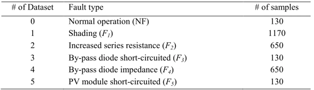
383.4.1 PVA without fault (NF)
…….……….……….
423.4.2 Partial shading fault (F1)
……….……….……
423.4.3 Increased series resistance (F2)
………….………….……….
433.4.4 By-pass diode short-circuited (F3)
………….………….……..
433.4.5 By-pass diode impedance (F4)
………….………….………..
433.4.6 PV module short-circuited (F5)
………….………….……….
443.5 Conclusion
…….………….………….………….……..
45REFERENCES
…….………….………….………….……..
46Chapter 4: Construction and Reduction of
Classifier’s Features (Inputs) ………...
494.1 Introduction
…….………….………….………….……..
494.1.1 Reasons behind Features Reductions Techniques
……….……
494.1.2 Review of Feature selection techniques
…….………..…
504.1.3 Research Contribution Obtained in this Chapter
…….……….
514.2 Features construction
…….………….………….…………
514.2.1 Feature 1: I-V curve area (S1)
.
…….………….………..
514.2.2 Feature 2: short-circuit current (S2).
…….……….……
524.2.3 Feature 3: open-circuit voltage (S3)
.
…….……….……
524.2.4 Feature 4: maximum power point (S4).
…….……….….…
524.2.5 Feature 5: voltage at the maximum power point (S5)
.
……….…
524.2.6 Feature 6: current at the maximum power point (S6)
……….…
534.2.7 Feature 7: I-V curve slope at the vicinity of Voc (S7).
………
534.2.8 Feature 8: I-V curve slope at the midpoint between MPP and --- open---circuit voltage point (S8)
.
…….………...…
534.2.10 Feature 10: I-V curve slope at short-circuit current Isc (S10)
……….
53 4.2.11 Feature 11: I-V curve slope at the midpoint between short circuit current---point and MPP(S11)
…….……….……..………..………..…
534.2.12 Feature 12: filling factor (S12)
………….………….……….
543.3 Feature Reduction for MC-NFC Building
…….………….……
563.3.1 Feature selection for each neuro-fuzzy classifier
…….………...…..
563.4 Conclusion
…….………….………….………….………
59REFERENCES
…….………….………….………….……..
61Chapter 5: Fault Classification Using Artificial
Intelligence Algorithms ………..…
645.1 Introduction
…….………….………….………….…….
645.1.1 Existing Detection and Classification Methods and their Limitations
…….
64 5.1.2 Research Contributions Obtained in this Chapter……….……
665.2 Basics of Artificial Intelligence Based Classifiers
…….…………
67 5.2.1 Steps Toward Multiclass Neuro-Fuzzy Classifier Development…………...
67 5.2.2 Basics of Artificial Intelligence Techniques…….………..…
67 5.2.3 Artificial Intelligence Techniques in PV Arrays…….…………...
695.3 Multi-Class neuro-fuzzy Classifier (MC-NFC) Development
….….
70 5.3.1 The Building blocks for MC-NFC Classifier…….………….….
705.3.1.1 Fuzzy Classifier
…….………….………..……..
705.3.1.2 Artificial Neural Network (ANN) Classifier
…….………..….
725.3.2 Detailed MC-NFC for FDC
…….………….…………..…..
735.3.2.1 Threshold Detection
…….………….………..….
735.3.2.4 Classifier performance evaluation criterions
…….………
775.4 FDC Experiments in PV Systems
…….………….………….
785.4.1 Experimental Setup
…….………….………….………….
785.4.2 Experimental Results
…….………….………….…………
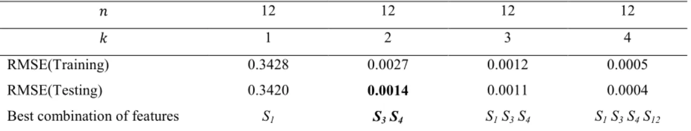
795.4.2.1 Experiment 1: Feature selection for each neuro-fuzzy classifier
…….
79 5.4.2.2 Experiment 2: MC-NFC building with reduced feature space……...
80 5.4.2.3 Experiment 3: Classification with artificial neural (ANN) classifier….
885.4.3 Discussion
…….………….………….……..……….…
885.5 Conclusion
…….………….………….………….……..
89REFERENCES
…….………….………….………….…….
90Chapter 6: Conclusions and Future Work …………..
936.1 Conclusions
…….………….………….………….…….
936.2 Future Work
…….………….………….………….……
96List of Publications……….…………...
98Figure 1.1: Fire hazards in a 1,208kW PV array,
in Mount Holly, North Carolina, in 2011
….….……….…….………….
2Figure 1.2: Fire hazards in a 383kW PV array, in Bakersfield, California, in 2009
.…
3 Figure 1.3: Schematic diagram of a grid-connected PV system, together with different types of faults in the PV array….……….………..
4Figure 2.1: Figure 2.1: (a) good bypass diode and blocking diode, (b) damaged diode. 9 Figure 2.2: (a) good junction box; (b) damaged junction box.
………..
10Figure 2.3: Hot Spot fault: causes (a) Shading, (b) Hot Spot phenomena in PVM, (c) Soiling and dust accumulation, (d) Hot Spot damage in PVM
……….
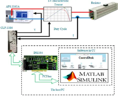
11Figure 2.4: The first undetected ground fault between a grounded current-carrying conductor (i.e., the negative conductor) and the equipment-grounding conductor. 13 Figure 2.5: The second ground fault between an ungrounded current-carrying conductor (i.e., the positive conductor) and the equipment-grounding conductor. 13 Figure 3.1: Schematic of the photovoltaic emulator with an APS61102A Programmable Power Source.
………
31Figure 3.2: Photograph of the emulator used for data collection
………
33Figure 3.3: single diode model.
………..…
34Figure 3.4: Bishop model.
………...…
34Figure 3.5: DC/DC buck converter used as current-voltage characteristics plotter.
.…
35 Figure 3.6: I-V curves of different PV array faults.……….……
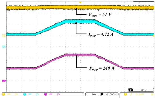
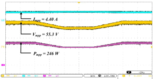
36Figure 3.7: Voltage, Current, and Power curves measured by changing irradiance, where configuration-1 is used.
………
37 Figure 3.8: Voltage, Current, and Power curves measured by changing temperature,Figure 3.9: Flowchart of the diagnostic algorithm
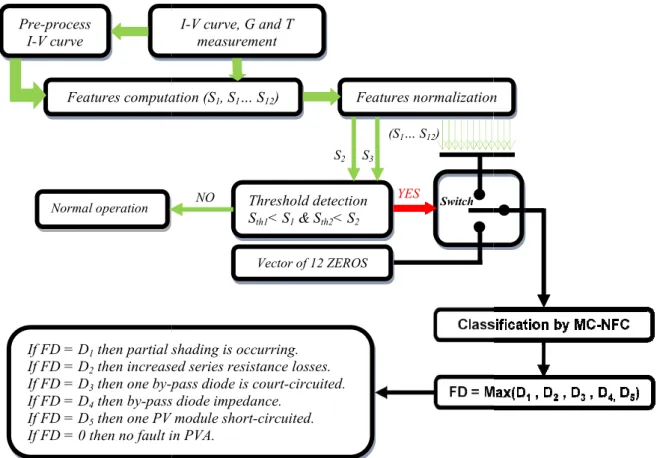
………...
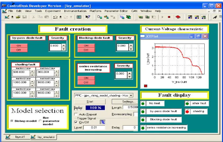
39 Figure 3.10: ControlDesk interface showing Shading fault condition, where configuration-2 isused.
………...………
40Figure 3.11: ControlDesk interface showing Increased Series Resistance condition, where
configuration-2 is used.
………...
40Figure 4.1: Overview of the proposed method for real-time fault detection and
classification phase of unknown samples.
………
55Figure 4.2: The structure of the fault detection and classification algorithm based on
classifiers decision outputs fusion.
………….……….……
55 Figure .4.3: Overview of the proposed method used for inputs (features) classifier
reduction.
………….……….……….…
57 Figure .5.1: Process of classifier building for fault detection and classification in a
PVA
………….……….……….………
67Figure .5.2: simplified flowchart of Artificial Intelligence techniques: Artificial Intelligence (AI), Machine learning (ML), Representation learning and deep learning
..
68
Figure .5.3: Types of machine learning
………….……….…
68Figure .5.4: Schematic of the proposed FDC model for PVA.
………….……
69 Figure .5.5: Fault Fuzzy classifier implementation concept.………….……..
71 Figure .5.6: Multi-layer neural network concept.………….………..
72 Figure .5.7: Scheme used for precision and recall computation in the detection phase...
73 Figure .5.8: ANFIS architecture with two inputs, two membership functions and oneoutput
………….……….……….……
75Figure .5.9: Diagram block of the MC-NFC concept.
………….…………
77 Figure .5.10: The structure of the fault detection and classification algorithm based onFigure .5.11: FIS Membership functions for initial and trained classifier (classifier’s 1
Inputs).
………….……….……….……
84Figure .5.12: FIS Membership functions for initial and trained classifier (classifier’s 2
Inputs).
………….……….……….……
85Figure .5.13: FIS Membership functions for initial and trained classifier (classifier’s 3
Inputs).
………….……….……….……
86Figure .5.14: FIS Membership functions for initial and trained classifier (classifier’s 4
Inputs).
………….……….……….……
86Figure .5.15: FIS Membership functions for initial and trained classifier (classifier’s 5
Inputs).
………….……….……….……
87Figure 6.1: Schematic diagram of a typical grid-connected PV system, including
TABLE 3.1: PV module’s electrical characteristics and temperature coefficients
(JW-50P)
………….……….……….….
33TABLE 3.2: Datasets for normal and faulty cases of the investigated PVA
……...
44 TABLE 4.1: Features (inputs) selection for F1 classifier………….………..
58TABLE 4.2: Features (inputs) selection for F2 classifier
………….………..
58TABLE 4.3: Features (inputs) selection for F3 classifier
………….………..
58TABLE 4.4: Features (inputs) selection for F4 classifier
………….………..
59TABLE 4.5: Features (inputs) selection for F5 classifier
………….………..
59TABLE 5.1: Errors of F1 classifier membership functions types during the
optimization process
………….……….………..
81TABLE 5.2: Errors of F2classifier membership functions types during the
optimization process
………….……….………..
81TABLE 5.3: Errors of F3classifier membership functions types during the
optimization process
………….……….………..
82TABLE 5.4: Errors of F4classifier membership functions types during the
optimization process
………….……….………..
82TABLE 5.5: Errors of F5classifier membership functions types during the
optimization process
………….……….………..
82TABLE 5.6: Errors of all classifiers membership functions number during the
optimization process
………….……….………..
83TABLE 5.7: Summary of the ANFIS models structures andoptimal parameters. 87 TABLE 5.8: Comparison between MC-NFC and ANN-classifier
………….…
88AC Alternative Current
AF Arc Fault
AFCI Arc Fault Circuit Interrupter AFD Arc Fault Detector
AI Artificial Intelligence
AIT Artificial Intelligence Techniques
ANFIS Adaptive Neuro-Fuzzy Inference System ANN Artificial Neural Network
BkD Blocking Diode
BpD Bypass Diode
DC Direct Current
DF Diode Fault
ECM Earth Capacitance Measurement ENN Extension Neural Network
EWMA Exponentially Weighted Moving Average
F Fault
FC Fault Classification
FC Fuzzy Classifier
FD Fault Detection
FDC Fault Detection and Classification FDM Fault Detection Method
FF Fill factor
FFT Fast Fourier Transformer
Fi Fault number i
FIS Fuzzy Inference System
FPGA Field-Programmable Gate Array GBSS Graph-Based Semi-Supervised GCPV grid-connected PV
GCPVS grid-connected PV system
GF Ground Fault
GFDI Ground Fault Detection Interrupter
I-V Current-Voltage
I-VCA I-V Characteristics Analysis
JB Junction Box
JSC Joint Research Centre
LL Line-to-Line
LLF Line-to-Line Fault
LM Levenberg-Marquardt
MC-NFC Multiclass Neuro-Fuzzy Classifier MDL Multi Level Decomposition
MF Membership Function
ML Machine Learning
MLP Multilayer Perceptron
MPPT Maximum Power Point Tracking MPRE Mean percent relative error
MS Monitoring System
MSC Multi-resolution Signal Decomposition NEC National Electrical Code
NFC Neuro-Fuzzy classifier
NO Normal Operation
OC Over Current
OCPD Over Current Protection Devices PCS Power Conditioning System PID Potential-Induced Degradation PLA Power Losses Analysis
PR Power Ratio
PV photovoltaic
PVA photovoltaic array
PVE PV Emulator
PVM Photovoltaic Module
PVMF PVM Fault
PVP PV Plant
PVS PV System
RBF Radial Basis Function RMSE Root Mean Square Error
SC Short Circuit
Si Feature number i
SSE Sum squared error
SSPA Statistical and Signal Processing Approaches SS-PVA Small-Scale PV Array
SS-PVP Small-Scale PV Plant SS-PVS Small-Scale PV system
STD Standard deviation
T-S Takagi-Sugeno
TDR Time-Domain Reflectometery VCM Voltage and Current Measurement VCM Voltage and Current Measurement Voc Open –Circuit Voltage
VR Voltage Ratio
Vth Threshold Voltage
WSN Wireless Sensor Network
K Degree Kelvin
a Bishop tuning parameter
A diode ideality factor
a-Si amorphous –Silicon
° C Degree Celsius D Duty Cycle G Irradiance GW Giga Watt I Current I sc Short-Circuit Current I0 dark saturation current
Im Maximum Current
Iph photo-current
k Boltzmann constant
KVA Kilo Volt Ampere
KW Kilo Watt
kWp Kilo Watt Peak
m Bishop tuning parameter
MW Mega Watt Pm Maximum Power q electron charge RS Series Resistance Rsh shunt resistance T Temperature Tstc (K) temperature in STC V Voltage Vbr Breakdown Voltage Vm Maximum Voltage
Voc Open-Circuit Voltage
Vrms Root Mean Square of Voltage
CHAPTER 1
Introduction
1.1. Background and Motivation
Photovoltaic systems’ reliability is defined in terms of maximizing the electricity production, and minimizing the factors that cause the power losses of the photovoltaic array (PVA), which is related to the implemented strategies for Maximum Power Point Tracking (MPPT) algorithms [1.1-1.3] and protection devices avoiding both energy and material losses [1.4]. At the end of 2016, 303 GW of photovoltaic energy was installed around the world. About 75 GW installed only in the year of 2016 [1.5], and this is comes from the fact that new solutions have encouraged government to rely more and more on this kind of energy. PVS like all electrical and electronic systems can break down and degrade during the operating period. This requires a diagnostic whose main objective is to provide an automatic tool that can early detect defects to protect peoples and installations, and in addition classifying these defects.
To stop unexpected events in solar photovoltaic (PV) systems, fault detection and protection are essential. Solar PV systems are subject to various faults along the PV arrays, power conditioning units, battery banc, cabling, and utility interconnections [1.1, 1.2]. It is difficult to shut down PV array completely during faults, since they are energized by sunlight. In a large PV array, it may become difficult to properly detect or identify a fault, which can remain hidden in the PV system until the whole system breaks down. In addition, conventional series-parallel PV configurations increase voltage and current ratings, leading to higher risk of large fault currents or dc arcs.
Due to faults occurring within PV arrays, several fires have been reported in PV systems [1.6-1.9]. Figure 1.1 shows a fire case in a 383 kW PV array in Bakersfield, California in 2009 [1.6, 1.7]. Another fire is illustrated in Figure 1.2, which occurred in a 1 MW PV power plant in Mount Holly, North Carolina, in 2011 [1.9]. In these cases, the fault remained undetected in the PV installation until the catastrophic fire is initiated. These fire cases not only show the failing in conventional fault detection and protection designs in PV arrays, but also disclose the urgent need of a better way to stop such issues.
Figure 1.1: Fire hazards in a 1,208kW PV array, in Mount Holly, North Carolina, in 2011 [1.9].
Due to the large usage of real time simulators in PV systems, there has been a possibility of PVA faults creation, repeating and changing easily. As a result, excessive PV data can be collected (both for faulty and healthy PVA). For example, as shown in Figure 1.3 a typical grid-connected PV system, various PV data can be collected. These PV data are mainly used to train and test classifiers and thus evaluate the PV system performance and calculate the energy losses. Hence, it is possible to develop more responsive fault-detection classifiers that can make better use of these readily available PV data.
Figure 1.2: Fire hazards in a 383kW PV array, in Bakersfield, California, in 2009 [1.6]. The existing fault detection and classification algorithms are built using fixed classifier’s inputs and fault scenarios that do not cover all possible real cases. Constructed features (classifier’s inputs) are applied without prior information on their effect on the classifier performance. Moreover, what it is known certainly, is that the constructed features have not the same effect on the classifier decision (output), some of them have the same effect, and some others have no effect on the classifier output at all. These reasons conduct us to reduce the classifiers’ inputs space. This leads, to avoid redundant information, in the case where some collinear features exist, and also eliminating features that have no effect on output of the decision function. Thus, optimized architectures are designed.
1.2. Problem statement
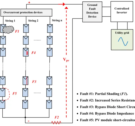
Figure 1.3 shows a typical grid-connected PV system including a PV array, a PV inverter, protection devices (OCPD, GFDI). Many fault types could occur within PV arrays, such as increased series resistance, ground faults, open-circuit faults, and bypass diode fault. Conventional fault detection and protection methods usually use OCPD (e.g., fuses) and GFDI with PV components [1.10] to protect PV components from large fault current.
However, certain faults in PV arrays may not be cleared by OCPD or GFDI due to non-linear output characteristics of PV arrays, PV current-limiting nature, high fault impedances, low irradiance conditions, PV grounding schemes, or MPPT of PV inverters [1.11]. These drawbacks fetch what is known under the name of “blind spots” in the readily protection solutions, leading to more power losses in PV system, accelerates system aging. DC arcs and similar fire hazards are reported in [1.9, 1.11].
Figure 1.3: Schematic diagram of a grid-connected PV system, together with different types of faults in the PV array.
1.3. Thisis Organization
Motivated by the previously discussed research problems, this thesis aims to analyze and elucidate the restrictions of existing methods and to recommend new fault detection and classification method. Thus, fault detection gap in solar PV arrays are limited. Specifically, the thesis is organized as follows:
Fault #1: Partial Shading (F1).
Fault #2: Increased Series Resistance (F2). Fault #3: Bypass Diode Short Circuited (F3). Fault #4: Bypass Diode Impedance (F4). Fault #5: PV module short-circuited (F5).
Utility grid
+
-
Overcurrent protection devices
String 1 String 2 String n
Ground Fault Detection Device Centralized Inverter Vpv F1 F2 F4 F5 F3
The state of the art is presented in Chapter 2. Chapter 3 explains how to collect data from PVA emulator for detection and classification algorithms development purpose. Chapter 4 focuses on classifier inputs (features) reduction techniques. Chapter 5 develops the multiclass neuro-fuzzy classifiers that detect and also classify faults in PVA. In Chapter 6, a brief summary of the research results is presented and future research works are addressed.
In chapter 2: State of the Art of fault detection and classification methods in Photovoltaic
Array will be presented.
Faults that can occur in PVA will be presented.
The existing fault detection and classification methodologies will be presented.
In chapter 3: A Real Time Emulator will be development and Data sets for classifiers training
and testing will be collected.
A real time emulator for PVA is developed for data collection. Thus, detection and classification algorithms development.
The model of PVA is implemented in a DS1104 platform, where is able to create faults and record data for faulty and healthy cases.
Control algorithms for MPPT are tested successfully with changing irradiance and then with changing temperature. Diagnosis algorithms was also tested and implemented.
An interface human/machine was created in ControlDesk software of ds1104 platform for facility of manipulation.
A sufficient number of data was recorded in Matlab workspace for further processing. In fact, a total of 2860 couples of current-voltage characteristics combined with its corresponding values of irradiance and temperature.
In chapter 4: classifier’s features will be constructed and reduced.
Features are constructed using mathematics formulas, new features are introduced.
A Matlab program is developed in order to reduce the classifier input dimensionality. Features are selected for each classifier.
A standard algorithm was implemented in Matlab to choose the best set of features for each classifier.
In chapter 5: Fault Classification Using Artificial Intelligence Algorithms
The limitations of existing methods for PV fault detection and classification are explained.
The building blocks for Multiclass Neuro-Fuzzy Classifier (MC-NFC) classifier are presented (fuzzy classifier and neural network classifier).
A Multi-Class Neuro-Fuzzy Classifier is developed for fault detection and classification in PVA. The developed classifier is compared to the artificial neural network (ANN) classifier.
The proposed classifier is implemented and tested with experimental PVA data.
In chapter 6: Conclusions and Future Research
The conclusions and future research are presented.
1.4 Contributions
This thesis shows some key research contributions and scientific improvements over the existing solutions.
1- First, new features have been introduced into the classifier input. Namely, I-V curve area and slopes at different points of the I-V curve.
2- A new way for classifier inputs’ is presented, starting by using many features and then reducing their number by using features dimensionality reduction techniques. This alternative solution saves a lot of time for classifiers development.
3- Third, in the proposed method some patterns of faults are used, but it can detect all possible real patterns for the concerned fault.
4- Finally, a MC-NFC is developed to discriminate between five different types of faults in a PVA.
REFERENCES
[1.1] Mellit, A., Rezzouk, H., Messai, A., & Medjahed, B. (2011). FPGA-based real time implementation of MPPT-controller for photovoltaic systems. Renewable
Energy, 36(5), 1652-1661.
[1.2] Mellit, A., & Kalogirou, S. A. (2014). MPPT-based artificial intelligence techniques for photovoltaic systems and its implementation into field programmable gate array chips: Review of current status and future perspectives. Energy, 70, 1-21.
[1.3] Dhimish, M., Holmes, V., & Dales, M. (2017). Parallel fault detection algorithm for grid-connected photovoltaic plants. Renewable Energy, 113, 94-111.
[1.4] Article 690 - Solar Photovoltaic Systems, NFPA70, National Electrical Code, 2016. [1.5] IEA, Snapshot of global photovoltaic markets, IEA PVPS T1-31:2017.
[1.6] Brooks, B. (2011). The Bakersfield fire-A lesson in ground-fault protection. SolarPro
Mag , 62-70.
[1.7] Jackson, P. (2009). Target roof PV fire of 4-5-09, 9100 rosedalehwy Bakersfield, California, City of Bakersfield, CA Development Services. Building Department
Memorandum, 4-29.
[1.8] Ladd, C., Taylor, J., Whitley, J. R., Cowperthwaite, C., & Leegard, R. (2011). Improving the safety and reliability of commercial solar electric systems. Southern
Energy Menagment.
[1.9] NC PV DG program SEPA presentation. Duke Energy, (2011): 1-14.
[1.10] Yuventi, J. (2014). DC electric arc-flash hazard-risk evaluations for photovoltaic systems. IEEE Transactions on Power Delivery, 29(1), 161-167.
CHAPTER 2
State of the Art
2.1 Introduction
Photovoltaic Arrays are subject to many failures, mainly due to the external operating conditions. Faults in photovoltaic system (PVS) are caused by: shading effects, module soiling, inverter failure, and mismatch due to variation in manufacturing or aging of PV modules (PVM). The main catastrophic failures in PV arrays (PVA) are: the line-to-line fault (LLF), ground fault (GF) and arc fault (AF) [2.1].
Fault detection and classification (FDC) for PVA, is an essential task to protect this latter from damage and fire risks [2.2, 2.3]. The main task of fault detection (FD), in PVA, consists of comparing the difference between the measured and calculated parameters with reference values, in order to verify the occurrence of any fault, while the fault classification (FC) identifies the type of faults [2.4]. Fault localization remains a big challenge, particularly in large scale PV plants [2.5]. A review on the application of non-electrical methods (e.g. infrared, thermal imagining) for FDC of PVA is presented in [2.6, 2.7]. The most common techniques on image analysis can detect and localize faults, but they have been applied and verified only for SS-PVP. A brief review on fault detection and monitoring systems was published recently in [2.8], in which the authors addressed the major PVS failures.
This chapter presents the state of the art of fault detection and classification (FDC) techniques for PVA. Different fault types are reported in this chapter.
2.2. Types of faults in PVA
Any fault occurring in PVA causes efficiency reduction, output power reduction, and safety hazards. Different types of fault in PVM are detailed in [2.9]. These include discoloration, cracking, antireflection coating damage, bubbles, soiling, busbar oxidation and corrosion, back sheet adhesion loss, etc. Some failure modes detection methods are presented in [2.10]. The faults consist of: bypass and blocking diodes faults, faults in a junction box, hotspot, faults in a PVM, PVA, arc, line-to-line faults and ground fault.
2.2.1 Bypass Diode fault and Blocking Diode fault (DF)
The electrical faults associated to these diodes are: short circuited diode, open circuited diode and impedance. The common reason of these faults may occur when shading in PV module/array for a long period of time [2.11, 2.12] is occurred. Bypass diode (BpD) is a key element for safe system operation [2.13]. However, blocking diode (BkD) in series with PVM will stop Over Current Protection Devices (OCPD) to operate correctly [2.14]. The reverse current under LLF will be cut off by BkD and the system fails.
(a) (b)
Figure 2.1: (a) good bypass diode and blocking diode, (b) damaged diode. 2.2.2 Junction box fault (JBF)
Corrosion occurred in junction box (JB) may lead to a quick increase in contact resistance [2.15]. An electric arc between the contact leads to wearing out and melting of the JB. This would finally damage the modules and the whole array, causing the PVS owner further damages due to loss of energy production.
(a) (b) Figure 2.2: (a) good junction box; (b) damaged junction box. 2.2.3 PV module fault (PVMF)
The faults on the PVM can occur when the array is isolated from the ground, due to corrosion, delamination of the PVM, leakage currents within a module and manufacturing defects which may lead to shunted module and short circuit within a module [2.16]. Generally, faults in PVM may cause electrical shock hazard and fire risk.
2.2.4 Hot spot (HS) fault
Hot Spot (HS) can be caused when some cells in a PV string/array have different I-V curves [2.17], i.e., there are variations in I-V characteristics of PVMs, high resistance or cold solder points due to manufacturing processes [2.17]. In addition, such characteristic may be affected by soiling and dust accumulation [2.18], degradation of the cells, incomplete edge isolation [2.19] by transparent module materials or by the manufacture's tolerance and the non-uniform insolation. The partial shadow effect can be considered as a particular case of the mismatch fault. The HS phenomenon can result when the bypass diode of the shaded cells is damaged/disconnected, thus its current decreases and its voltage becomes negative, so the shaded cells consumes power from other non-shaded cells instead of generating it [2.20], and if this phenomenon persists the affected solar cells will be damaged [2.21]. Some methods for detecting HS are reported in [2.22], but many techniques for quick detection of HS in a PVM are based on infrared measurements.
(a) (b)
(c) (d)
Figure 2.3: Hot Spot fault: causes (a) Shading, (b) Hot Spot phenomena in PVM, (c) Soiling and dust accumulation, (d) Hot Spot damage in PVM
2.2.5 Arc faults (AF)
An Arc Fault (AF) is the unintended flow of current through air or another dielectric. AFs are generally divided into two categories [2.23]:
Series AF: arc from discontinuity in electrical conductor
Parallel AF: electrical discharge between conductors with different potentials.
An AF Detector (AFD) should be included in each system. There are two approaches to detect an AF; the first one is based on the measured value of the DC current in a conductor, it consists of adding small impedance in series with the circuit and measures the resultant voltage. While, the second is based on the measured value of the AC current in a conductor, this approach is relatively easy, due to the oscillatory nature of an AC current; a transformer
may be used as the sensing element. More details about both approaches can be found in [2.24]. Parallel and series AF must be de-energized to protect PVS from fires [2.23]. With reference to NEC 2011, Article 690.11 [2.24] a PV system higher than 80 V penetrating a local or a utility network is suggested to integrate an AF circuit interrupter (AFCI) device as a protection measure.
2.2.6 Line-to-Line fault (LLF)
A line to line fault (LLF) is an unintended low-resistance connection between two points of different potential in an electrical network or system. In PVS, a LLF is usually defined as a short-circuit fault among PVM or array cables with different potential [2.25]. LLF in PVA may be caused by: insulation failure of cables, incidental short circuit between current carrying conductors, low insulation between string connectors in DC string box and mechanical damage. To protect the PVA from LL incidents, many companies have developed protecting devices.
2.2.7 Ground fault (GF)
A ground fault (GF) in PVA can be considered as an unintended electrical short circuit connecting ground and one or more normally designated current-carrying conductors [2.26]. GF in PVA often represent people's safety issues because they may generate DC arcs at the fault point on the GF path. If the fault is not removed properly, the DC arcs could maintain and cause a fire hazard [2.14, 2.26]. Identifying ground faults is a significant problem in ungrounded PVS because such earth faults do not provide sufficient fault currents for their detection and location during system operation [2.27]. GF is the most common fault in PVS and may be caused by the following reasons [2.26]: secondary short circuit between normal conductor and ground, insulation failure of cables, and GF within PVM.
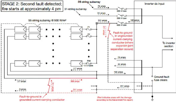
Figures 2.4 and figure 2.5 are taken from [2.28]; in figure 2.4 the fault remains undetected, unless the fault shown in figure 2.5 is detected and cleared.
Figure 2.4: The first undetected ground fault between a grounded current-carrying conductor (i.e., the negative conductor) and the equipment-grounding conductor.
Figure 2.5: The second ground fault between an ungrounded current-carrying conductor (i.e., the positive conductor) and the equipment-grounding conductor.
2.3 Existing Fault detection and classification methods
Many systems have been recently proposed intending to perform a real-time monitoring of PV array (PVA); in this context all methods should respond to the standard IEC 61724 requirements [2.29], and the guidelines of the European Joint Research Centre (JSC) in Ispra, Italy [2.30, 2.31].
Several FDC methods have been proposed in literature, the main features that can characterize such methods are: detecting the defect quickly, the input data required (climatic and electrical data), and selectivity (i.e., ability to distinguish between different faults). They can be classified into two main groups:
Visual & thermal methods [2.7], which can be used for detecting discoloration, browning, surface soiling, hot spot, breaking, and delamination, and;
Electrical methods that can be used for detecting and diagnosing faulty PVM, strings and arrays including arc fault, grounding fault, diodes fault, etc.
Most electrical-based FDC methods rely on some type of PVA model to detect various types of faults.
Electrical methods can be classified into five groups [2.32]: statistical and signal processing approaches (SSPA); I-V characteristics analysis (I-VCA);
power losses analysis (PLA);
voltage and current measurement (VCM); Artificial intelligence techniques (AIT).
Some FDC methods based on electrical techniques are recently reported in [2.33].
In this chapter, we did not present Visual & thermal based methods, the readers can be reported to [2.7] for more information.
2. 3.1 Methods based on statistical signal and processing approaches (SSPA)
Signal processing methods are mainly based on the analysis of the signals. In [2.34], time-domain reflectometery (TDR) technique is used to find the position of the failed PVM in a PVA. The authors underlined that the method can be employed for fault detection and localization, however the method is dependent on the installation conditions such as modules mounting, wiring, or PVA components materials.
An electrical method [2.35] is based on the Earth Capacitance Measurement (ECM) and TDR to detect which PVM in a string is disconnected. According to the authors, the ECM can be used to detect the disconnection positions between the PVM in the string without the effects of the irradiance change, and the TDR could detect the position of the degradation, such as the increase in the Rs between the PVs. The work done by Takashim et al. [2.35] showed that the ECM method could be applied not only to a PV string consisting of crystalline Si PVM, but also to a string consisting of amorphous –Silicon (a-Si) PVM. The TDR technique [2.36] was used to detect breaks of the circuit, insulation defects, wiring anomalies in strings including open circuit and inversed polarity. A 1 MW PV plant (PVP) was tested for a couple of days. The method is basically based on the analysis of the waveform of the output voltage.
An AF circuit protection technique is proposed in [2.37]. This technique can be used to detect and interrupt arcing faults resulting from a failure in the intended continuity of a conductor, connection, module, or other system components in the direct current PV source and output circuits. In [2.38], the authors developed a fault detection method (FDM) for a grid-connected PV system (GCPVS) using wavelet transform (WT). The advantage of the method is the simple calculation and precise diagnostic capabilities of the fault diagnosis. A monitoring system (MS) which provides real-time measurements of each PVM's voltage and current is considered in [2.39]. The presented method employs a classical approach to outlier detection, employing more recent work in robust statistics to overcome the problem of multiple clustered anomalous observations. It has been examined only for two types of faults, AF and GF [2.39]. As reported in [2.40], it is possible to detect AF using Fast Fourier Transform (FFT), but it is not as significant as using WT, particularly when it comes to the problem for a threshold setting for AF determination. The proposed method is validated experimentally with good results.
Recently, a statistical method named exponentially weighted moving average (EWMA) chart is developed in [2.41], the method is used to investigate the following faults: short-circuit, open circuit and shading in PVS. The method has been tested for a GCPV system and the results are very promising.
2. 3.2 Methods based on the I-V characteristic analysis (I-VCA)
Fault diagnosis of PVA based on the I-V characteristic is firstly introduced in [2.16], in which a procedure for the detection of PVA faults is proposed. It consists of comparing the actual to expected electrical parameters from I-V characteristics. Faulty disconnection in PVA is investigated. Experimental testing has demonstrated the ability of the method to detect some PVA faults. The analysis of the shape of the I-V characteristic of PVA cannot always detect faults. For this reason, Miwa et al. [2.42] have proposed a method based on the analysis of the (dI/dV)-V characteristic in order to evaluate automatically the output drop of PVS caused by different loss factors. It was demonstrated that an appearance of a peak of the (-dI/dV)-V characteristic is effective to diagnose the power output drop of a PVS.
Five common types of faults (mismatch, DF, connectivity, PVMF and GF) in PVA were investigated in [2.43]. A Matlab/Simulink based model is developed for this study. Simulation results show that the designed model can simulate the different faults investigated. Daliento et al. [2.44] developed a novel method to detect failures based on simple electrical measurements. The authors analyzed the first and the second derivation of I-V curve in order to detect possible faults in RS and BpD. The method is simulated and validated experimentally, although the applicability of the method is limited.
2. 3.3 Methods based on the power losses analysis (PLA)
An automatic supervision and FD procedure, based on the PLA is proposed in [2.45], which permits to identify three groups of faults and a false alarm: faulty modules in a string, faulty string, and a group of different faults such as partial shadow, ageing, and MPPT error. The automatic supervision method is based on the analysis of the power losses present in the DC side of the PVA and capture losses. Two kinds of capture losses have been introduced: thermal capture losses and miscellaneous capture losses. A procedure for fault diagnosis in PVS with distributed MPPT at module level, power optimizers DC-DC or micro-inverters DC-AC, is proposed in [2.46]. It has been shown that the designed procedure can diagnose a large scope of failures including: fixed object shading, possible HSs, small localized dirt,
module degradation, generalized dirt and cable losses. The method was experimentally verified.
Shimakage et al. [2.47] developed a fault detection system by comparing the present and past conditions in a faulty PVA, and the proposed method was evaluated at specific fault conditions based on the assumption that some modules are bypassed by the behavior of a BpD because of a module fault or a partial shadow on modules in a string. Multiple faults can be detected in the algorithm proposed in [2.48], in which they have used two indicators PR and VR in order to determine the fault type, time and the location where this fault occurred in the PV system. The method is based on a statistical analysis of data and theoretical thresholds. The method is not able to detect any fault occurred in AC side of the system.
2. 3.4 Method based on voltage and current measurements (VCM)
In [2.49] the authors developed a graph-based semi-supervised learning model for fault detection and classification in PVA. A graph-based semi-supervised learning has been proposed for possible detection of hidden faults in PVA. Experiments demonstrated that the proposed method can correctly detect and classify specific normal conditions, LLFs, and overcurrent (OC) faults in real-working conditions.
In [2.50] the authors define new current and voltage indicators (named: NRc and NRv) as well as the thresholds for both parameters to identify PV string and inverter failures. Investigated faults are: faulty string (one string in open circuit) and bypassed module (one PVM bypassed in one string). With respect to the authors, the proposed method is simple but effective while considering the minimum number of sensors and minimizes the monitoring and supervision system, which can be included in the inverter. Moreover, the supervision of the PVS could be carried out in real time by the inverter itself.
A hardware realization based on Arduino device has been realized for mismatch identification of solar cells [2.51]. Three parameters have been measured: voltage, temperature and resistance of the module. The method can detect easily the mismatch fault. A method for detecting the number of open and short circuit faults, and discriminate between them and partial shading condition is proposed in [2.52]. The method is based on the measurement of the operating voltage of PV string and ambient temperature. A case study for a PVA formed by 8 × 3 PVM was also presented and results showed that the algorithm is able to identify the actual fault of the system with high probability.
2. 3.5 Methods based on artificial intelligence techniques (AIT)
In the last decade artificial intelligence techniques (AIT) have proven their capability for modeling, control, prediction and forecasting in PVS [2.53].
A matter element model is combined with an ANN to build an intelligent fault diagnosis system as shown in [2.54]. According to the authors, the proposed fault diagnosis method was adopted to identify the faulty types of a 3.15 kW PVS. The simulation results indicate that the proposed fault diagnosis method can detect the fault types of PVS rapidly and accurately with lower time and memory consumption.
In [2.55] the authors presented a method on ANN-based Genetic Algorithm (GA) to diagnose and repair the PVS dynamically. They have shown that, the proposed method proved how good it is for the practical applications. The designed approach can be used for detecting the following faults: short-circuit (SC), open-circuit (OC) and degradation in PVM faults.
A fault diagnosis meter based on a ZigBee Wireless Sensor Network (WSN) for PV power generation systems is proposed in [2.56]. An Extension Neural Network (ENN) fault diagnosis method is used to identify whether the PV power generation system is operating normally or a fault has occurred. The method includes as inputs the solar irradiation and module temperature of the PVM and then using this information together with the characteristics captured from the PV power generation system, provide fault diagnosis, including Pm, Im, Vm and Voc of the PVA during operation.
A novel fault diagnostic technique for PVA based on ANN was proposed recently in [2.32, 2.57]. The analysis is performed using two different Algorithms:
Algorithm 1, implements a signal threshold approach and isolates the faults that have a different combination of attributes;
Algorithm 2, consists of an ANN based approach and detects the faults that are characterized by the same combination of attributes.
It has been demonstrated that the designed technique is able to detect and identify accurately the investigated fault categories in the PV string, using only the parameters of the I-V characteristic as well as the irradiance level and cell temperature.
A fault detection method for photovoltaic module under partially shaded conditions is introduced in [2.58]. It uses an ANN in order to estimate the output photovoltaic current and voltage under variable working conditions. The results confirm the ability of the technique to correctly localize and identify the different types of faults. The designed diagnostic method is cheap because it requires as input only the following parameters: solar irradiance, PV module's temperature, and PV array's current and voltage [2.58]. In [2.59] the authors developed a fuzzy logic technique for fault detection in a PVA. The designed algorithm is able to discriminate between the most frequently occurring PVM module faults, such as increased series losses, BpD and BkD with good accuracy (90–98%).
A method to detect line-to-line and line-to-ground fault, mainly based on the application of a multi-resolution signal decomposition (MSD) technique on fuzzy inference system is developed in [2.60]. Results show that the method is able to detect faults in a PV array, and it was demonstrated experimentally for a Small-Scale PV Array (SS-PVA). In [2.27] a fault detection method based on WT and ANN is developed for an ungrounded PV system. The designed method is able to detect and localize GF and LL faults in a PVA. Finally, the effectiveness of the designed fault locator is tested with a variety of system parameters. The results demonstrate that the proposed approach has accurate and robust performance even with noisy measurements and changes in operating conditions. A method based on the theoretical I-V curves analysis and FL classification system for fault detection in DC-side of a 1.1 kWp grid-connected PV system (GCPVS) is developed in [2.61, 2.62]. The investigated fault is partial shading effect in PV modules. The classification rate is more than 98%. Recently, the authors in [2.63] developed a novel fault diagnosis approach to detect and classify the following faults: degradation, open circuit, short circuit and partial shading effect on a PVA. The approach is based on the use of I-V curves and the emerging kernel based extreme learning machine. With reference to the authors, both the simulation and experimental results show that the designed approach can achieve high accuracy.
2.4 Existing Fault Protection Solutions
Once the fault is detected, a fault signal can activate interruption devices to clear the fault, in order to protect PV components from damage. The fundamental objective of system protection is to provide isolation of fault in the power system rapidly, so that the damage to the rest of the PV system is minimized [2.64].
In PV applications, the fault area in the solar PV arrays should be isolated so that the impact to the rest of the PV system is minimized. Passive methods use ground fault detection interrupters (GFDI), overcurrent protection devices (OCPD) or blocking diodes [2.65, 2.66]. On the other hand, active methods use more complex sensing circuitry to detect the fault, and rely on circuit breakers, contactors, or semiconductors switches to de-energize and isolate the affected PV components [2.67, 2.68].
Passive protection devices have obvious limitations. Furthermore, blocking diodes are not a substitute of OCPD and they can prevent OCPD from normal operation [2.65]. To improve fault protection, active fault protection devices have been developed and shown the advantages over passive ones. But, they greatly dependent on the fault detection methods (i.e., decision-making algorithms). Therefore, there is still a great need of fault detection methods that can provide responsive and reliable tripping signal to active protection devices.
For a thorough presentation of the existing methods for fault detection and classification the reader can be reported to [2.33, 2.69 and 2.70].
2.5 Conclusion
In this chapter, we present the state of the art of existing fault detection, classification, location and protection solutions for solar photovoltaic (PV) arrays (dc side). Required by the National Electrical Code (NEC), ground-fault detection interrupters (GFDI) and overcurrent protection devices (OCPD) are widely used for fault protection in PV installations. However, their weakness and limitations have been discovered, which may lead to the fire hazards.
To address this issue, a new method has been proposed using artificial intelligence techniques. Therefore, there is an urgent need of better fault detection methods to prevent PV systems from fault hazards.
REFERENCES
[2.1]. Alam, M. K., Khan, F., Johnson, J., & Flicker, J. (2015). A comprehensive review of catastrophic faults in PV arrays: types, detection, and mitigation techniques. IEEE
Journal of Photovoltaics, 5(3), 982-997.
[2.2]. Falvo, M. C., & Capparella, S. (2015). Safety issues in PV systems: Design choices for a secure fault detection and for preventing fire risk. Case Studies in Fire Safety, 3, 1-16. [2.3]. Krueger, J., & Smith, D. (2003). A practical approach to fire hazard analysis for
offshore structures. Journal of hazardous materials, 104(1-3), 107-122.
[2.4]. Al-Sheikh, H., & Moubayed, N. (2012). Fault detection and diagnosis of renewable energy systems: An overview. In Renewable Energies for Developing Countries
(REDEC), 2012 International Conference on, 1-7.
[2.5]. Hasenfus, G. D. (2012). U.S. Patent No. 8,294,451. Washington, DC: U.S. Patent and
Trademark Office.
[2.6]. Tsanakas, J. A., Vannier, G., Plissonnier, A., Ha, D. L., & Barruel, F. (2015). Fault diagnosis and classification of large-scale photovoltaic plants through aerial orthophoto thermal mapping. In Proceedings of the 31st European Photovoltaic Solar Energy
Conference and Exhibition 2015, 1783-1788.
[2.7]. Tsanakas, J. A., Ha, L. D., & Al Shakarchi, F. (2017). Advanced inspection of photovoltaic installations by aerial triangulation and terrestrial georeferencing of thermal/visual imagery. Renewable Energy, 102, 224-233.
[2.8]. Triki-Lahiani, A., Abdelghani, A. B. B., & Slama-Belkhodja, I. (2017). Fault detection and monitoring systems for photovoltaic installations: A review. Renewable and
Sustainable Energy Reviews.
[2.9]. Colli, A. (2015). Failure mode and effect analysis for photovoltaic systems. Renewable
[2.10]. Cristaldi, L., Faifer, M., Lazzaroni, M., Khalil, M. M. A. F., Catelani, M., & Ciani, L. (2015). Diagnostic architecture: A procedure based on the analysis of the failure causes applied to photovoltaic plants. Measurement, 67, 99-107.
[2.11]. Winter, C. J., Sizmann, R. L., & Vant-Hull, L. L. (Eds.). (2012). Solar power plants: fundamentals, technology, systems, economics. Springer Science & Business Media. [2.12]. Rezgui, W., Mouss, N. K., Mouss, L. H., Mouss, M. D., Amirat, Y., & Benbouzid, M.
(2014). Faults modeling of the impedance and reversed polarity types within the PV generator operation. In 2014 IEEE EFEA, 1-6.
[2.13]. Kato, K. (2012). PV module failures observed in the field-solder bond and bypass diode failures. 27th EUPVSEC.
[2.14]. Zhao, Y., Lehman, B., de Palma, J. F., Mosesian, J., & Lyons, R. (2011). Challenges to overcurrent protection devices under line-line faults in solar photovoltaic arrays.
In Energy Conversion Congress and Exposition (ECCE), 2011 IEEE (pp. 20-27). IEEE.
[2.15]. Jakobi WN K-M, Paterna M, Ansorge F, Baar C. K. (2014). Ring Faults of Contacts in PV Module Junction Boxes due to Fretting Corrosion. In: Proceedings of the 29th
European Photovoltaic Solar Energy Conference and Exhibition, 2505 –2510.
[2.16]. Stellbogen, D. (1993). Use of PV circuit simulation for fault detection in PV array fields. In Photovoltaic Specialists Conference, 1993, Conference Record of the Twenty
Third IEEE , 1302-1307.
[2.17]. Massi Pavan, A., Mellit, A., De Pieri, D., & Lughi, V. (2014). A study on the mismatch effect due to the use of different photovoltaic modules classes in large‐scale solar parks. Progress in photovoltaics: research and applications, 22(3), 332-345. [2.18]. Pavan, A. M., Mellit, A., & De Pieri, D. (2011). The effect of soiling on energy
production for large-scale photovoltaic plants. Solar energy, 85(5), 1128-1136.
[2.19]. Ndiaye, A., Charki, A., Kobi, A., Kébé, C. M., Ndiaye, P. A., & Sambou, V. (2013). Degradations of silicon photovoltaic modules: A literature review. Solar Energy, 96, 140-151.
[2.20]. Hu, Y., Cao, W., Ma, J., Finney, S. J., & Li, D. (2014). Identifying PV module mismatch faults by a thermography-based temperature distribution analysis. IEEE
Transactions on Device and Materials Reliability, 14(4), 951-960.
[2.21]. Yang, H., Xu, W., Wang, H., & Narayanan, M. (2010). Investigation of reverse current for crystalline silicon solar cells—New concept for a test standard about the reverse current. In Photovoltaic Specialists Conference (PVSC), 2010 35th IEEE, 002806-002810.
[2.22]. Simon, M., Meyer, EL. (2010). Detection and analysis of hot-spot formation in solar cells". Sol Energy Mater Sol Cells, 94:106–113.
[2.23]. Johnson, J., Montoya, M., McCalmont, S., Katzir, G., Fuks, F., Earle, J., & Granata, J. (2012). Differentiating series and parallel photovoltaic arc-faults. In Photovoltaic
Specialists Conference (PVSC), 2012 38th IEEE, 000720-000726.
[2.24]. McCalmonit, S. (2013). Low cost arc fault detection and protection for PV systems. Contract, 303, 275-3000.
[2.25]. Zhao, Y., Ball, R., Mosesian, J., de Palma, J. F., & Lehman, B. (2015). Graph-based semi-supervised learning for fault detection and classification in solar photovoltaic arrays. IEEE Transactions on Power Electronics, 30(5), 2848-2858.
[2.26]. PVPN1: "Ground-Fault Analysis and Protection in PV Arrays Tech topics: Photovoltaic protection"; 2011.
[2.27]. Karmacharya, I. M., & Gokaraju, R. (2017). Fault location in ungrounded photovoltaic system using wavelets and ANN. IEEE Transactions on Power Delivery.
[2.28]. Brooks, B. (2011). The bakersfield fire-a lesson in ground-fault protection. SolarPro
Magazine, 62-70.
[2.29]. IEC61724 S. (1998). Photovoltaic System Performance Monitoring – Guidelines for Measurement, Data Exchange and Analysis. IEC.
[2.30]. Blaesser GM. D. (1993). Guidelines for the Assessment of Photovoltaic Plants, Document A, Photovoltaic System Monitoring. Commission of the European
[2.31]. Blaesser GMD. (1993). Guidelines for the assessment of photovoltaic plants, document B, Analysis and presentation of monitoring data. Commission of the
European Communities, JRC, Ispra, Italy, EUR 16339 EN.
[2.32]. Chine, W., & Mellit, A. (2017). ANN-based fault diagnosis technique for photovoltaic stings. In Electrical Engineering-Boumerdes (ICEE-B), 2017 5th International
Conference on, 1-4.
[2.33]. Daliento, S., Chouder, A., Guerriero, P., Pavan, A. M., Mellit, A., Moeini, R., & Tricoli, P. (2017). Monitoring, diagnosis, and power forecasting for photovoltaic fields: a review. International Journal of Photoenergy, 2017.
[2.34]. Takashima, T., Yamaguchi, J., Otani, K., Kato, K., & Ishida, M. (2006, May). Experimental studies of failure detection methods in PV module strings. In Photovoltaic
Energy Conversion, Conference Record of the 2006 IEEE 4th World Conference on, 2,
2227-2230.
[2.35]. Takashima, T., Yamaguchi, J., & Ishida, M. (2008). Disconnection detection using earth capacitance measurement in photovoltaic module string. Progress in
Photovoltaics: Research and Applications, 16(8), 669-677.
[2.36]. Schirone, L., Califano, F. P., Moschella, U., & Rocca, U. (1994). Fault finding in a 1 MW photovoltaic plant by reflectometry. In Photovoltaic Energy Conversion, 1994.,
Conference Record of the Twenty Fourth. IEEE Photovoltaic Specialists Conference-1994, 1994 IEEE First World Conference on, 1, 846-849.
[2.37]. Dini, D. A., Brazis, P. W., & Yen, K. H. (2011). Development of arc-fault circuit-interrupter requirements for photovoltaic systems. In Photovoltaic Specialists
Conference (PVSC), 2011 37th IEEE, 001790-001794.
[2.38]. Kim, I. S. (2011). Fault detection algorithm of the photovoltaic system using wavelet transform. In Power Electronics (IICPE), 2010 India International Conference on, 1-6. [2.39]. Braun, H., Buddha, S. T., Krishnan, V., Spanias, A., Tepedelenlioglu, C., Yeider, T.,
& Takehara, T. (2012). Signal processing for fault detection in photovoltaic arrays.
In Acoustics, Speech and Signal Processing (ICASSP), 2012 IEEE International Conference on, 1681-1684.
[2.40]. Wang, Z., & Balog, R. S. (2013, June). Arc fault and flash detection in DC photovoltaic arrays using wavelets. In Photovoltaic Specialists Conference (PVSC),
2013 IEEE 39th, 1619-1624.
[2.41]. Garoudja, E., Harrou, F., Sun, Y., Kara, K., Chouder, A., & Silvestre, S. (2017). Statistical fault detection in photovoltaic systems. Solar Energy, 150, 485-499.
[2.42]. Miwa, M., Yamanaka, S., Kawamura, H., & Ohno, H. (2006). Diagnosis of a power output lowering of PV array with a (-dI/dV)-V characteristic. In Photovoltaic Energy
Conversion, Conference Record of the 2006 IEEE 4th World Conference on, 2,
2442-2445.
[2.43]. Fezzani, A., Mahammed, I. H., Drid, S., & Chrifi-alaoui, L. (2015). Modeling and Analysis of the Photovoltaic array Faults. In Control, Engineering & Information
Technology (CEIT), 2015 3rd International Conference on, 1-9.
[2.44]. Daliento, S., Di Napoli, F., Guerriero, P., & d’Alessandro, V. (2016). A modified bypass circuit for improved hot spot reliability of solar panels subject to partial shading. Solar Energy, 134, 211-218.
[2.45]. Chouder, A., & Silvestre, S. (2010). Automatic supervision and fault detection of PV systems based on power losses analysis. Energy conversion and Management, 51(10), 1929-1937.
[2.46]. Solórzano, J., & Egido, M. A. (2013). Automatic fault diagnosis in PV systems with distributed MPPT. Energy conversion and management, 76, 925-934.
[2.47]. Shimakage, T., Nishioka, K., Yamane, H., Nagura, M., & Kudo, M. (2011). Development of fault detection system in PV system. In Telecommunications Energy
Conference (INTELEC), 2011 IEEE 33rd International, 1-5.
[2.48]. Dhimish, M., & Holmes, V. (2016). Fault detection algorithm for grid-connected photovoltaic plants. Solar Energy, 137, 236-245.
[2.49]. Zhao, Y., Ball, R., Mosesian, J., de Palma, J. F., & Lehman, B. (2015). Graph-based semi-supervised learning for fault detection and classification in solar photovoltaic arrays. IEEE Transactions on Power Electronics, 30(5), 2848-2858.
![Figure 1.1: Fire hazards in a 1,208kW PV array, in Mount Holly, North Carolina, in 2011 [1.9]](https://thumb-eu.123doks.com/thumbv2/123doknet/2945765.79670/20.892.131.771.339.831/figure-hazards-pv-array-mount-holly-north-carolina.webp)