Official URL
https://www.htwsaar.de/htw/wiwi/Forschung%20und%20Wissenstransfer/publikationen/d
ateien/Proceedings_IESM2017.pdf
Any correspondence concerning this service should be sent
to the repository administrator:
[email protected]
This is an author’s version published in:
http://oatao.univ-toulouse.fr/26150
Open Archive Toulouse Archive Ouverte
OATAO is an open access repository that collects the work of Toulouse
researchers and makes it freely available over the web where possible
To cite this version: Hajmoosaei, Mojtaba and Tran, Hanh Nhi
and Percebois, Christian A User-centric Process Management for
System and Software Engineering Projects. (2017) In: 7th
International Conference on Industrial Engineering and Systems
Management (IESM 2017), 11 October 2017 - 13 October 2017
(Saarbrücken, Germany).
A User-centric Process Management
for System and Software Engineering Projects
(presented at the 7th IESM Conference, October 11–13, 2017, Saarbr¨ucken, Germany)
Mojtaba Hajmoosaei
IRIT, University of Toulouse, Toulouse, France [email protected]
Hanh Nhi Tran
IRIT, University of Toulouse, Toulouse, France [email protected]
Christian Percebois
IRIT, University of Toulouse, Toulouse, France [email protected]
Abstract—In traditional process environments, process mod-eling is performed by process designers and process enacting is performed by process actors. Due to this separation, there is often a gap between process models and their real enactments. As a consequence, the operational level of process environments has stayed low, especially in system and software industry, because they are not directly relevant to process actors’ needs. In order to facilitate the usage of process environments, this paper presents a solution that enables process actors to perform both the modeling and enacting of their real processes. To this end, first, an end-user process modeling approach was proposed to allow each process actor to easily describe the process fragment containing the activities carried out by his role. Second, an artifact-centric process engine was developed to enact activities coming from different process fragments. Our process engine does not require predefined work-sequence relations among these activities to synchronize them, but deduces such dependencies from their exchanged artifacts. As a result, the process engine can enact even a partially defined process where some fragments are missing.
I. INTRODUCTION
Modern System and Software Engineering (SSE) processes are often extremely complex, involve multi-disciplines and can be realized by different teams. Such complicated processes can be modeled and then applied to different projects. Process’s execution should be managed by a process environment that monitors and controls the project’s activities.
Most process environments adopt a top-down approach where the whole process is first modeled by process designer and then deployed in a project where real enactment happens by process actors, i.e., persons operating the process. However, in general it is almost impossible for process designers to model accurately the entire process as they don’t have a thorough knowledge about the process’s application domain. Thus, several details of the process may be left initially unspecified; some execution scenarios may be unseen and the process model does not describe exactly what will be done by process actors. Consequently, deploying a process model in a process environment to manage a project requires an important refinement [4] that is not evident for process actors. First, they are not trained to work with complicated process modeling languages. Second, they don’t have a global view on the process; each process actor only knows his own activities. For this reason traditional process environments have been still weakly adopted by end-users in system and software industry. To promote the practical use of process environments, we put the main emphasis on process actors and aim at providing
them a friendly environment allowing each process actor to model himself his working process so that the obtained model is closer to his real activities and thus executable after a simple deployment. In contrast to the top-down approach that requires the whole process model to enable its enactment and synchronization, we propose: (1) modeling the global process in separate fragments belonging to different roles and then (2) constructing dynamically the global view of the system at enactment-time to synchronize activities belonging to different process fragments that are progressively instantiated during the process’s execution. In order to achieve these objectives, we developed:
• A Structural Process Modeling Language enabling each process actor to specify his process fragment independently of other process fragments. To be more relevant to process actor’s vision about process, our language suppresses the work-sequence relations in process models but strengthens the description of artifact exchanges among process activities. This simple language will be described in Section III.
• An Artifact-centric Process Engine enacting process frag-ments performed by different process actors. The process en-gine analyzes the data exchanged among the running activities to deduce their inter-dependencies and then synchronize them. Section IV presents the proposed process engine.
In Section V, we report the experiments carried out by using our prototype process environment with participation of our industrial partners.
II. MOTIVATINGEXAMPLE
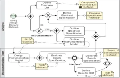
Figure 1 presents an extract of a process given by our industrial partners in the project FUI1 ACOVAS (Agile tools
for COnception and VAlidation of Systems) to reconfigure the wiring system of a testbench due to an evolution of the system under test. The process Modify Testbench Wiring concerns several expertise domains but we only focus on the electrical and instrumentation ones to simplify the description. The pro-cess is performed by five roles: Analyst, Electrical Designer,
Instrumentation Team, Wiring Teamand Bench Coordinator. In practice, each role describes his fragment of process as a list of activities that he performs, with their input and output ar-tifacts in a specific state. For instance, an Analyst performs the activity Detail Change Requirement, which receives the artifact
Change Demandin the state defined and produces three output artifacts: a Component Purchase List (defined), an Electrical
Fig. 1: Process Modify Testbench Wiring
Specification (defined) and a Functional Interface Control
Document (FICD) (outlined). Often, activities are described without an explicit execution order; their inter-dependencies however can be deduced by analyzing the artifacts that they exchange. For example, Design Electrical Model can only start after the termination of Detail Change Requirement because it requires the Electrical Specification produced by Detail
Change Requirement.
In a top-down approach, to obtain an executable process, the process designer must refine the process in Figure 1 to model the enactable tasks of all roles as well as their execution order in all possible circumstances that may happen at enactment-time. Figure 2 shows one possible modeling of the process fragments concerning the activities of Analyst and
Instrumentation Team.
Fig. 2: Process Modify Testbench Wiring in BPMN
For complex processes, this modeling is challenging, par-ticularly when tasks’ sequence is non linear because different modeling constructs as loops or choices are needed to ex-press execution orders. For example, inside the activity Detail
Change Requirement while the tasks, Define Purchase List and Define Electrical Specification are always performed, the task Outline Instrumentation Model will be enacted only if the option instrumentation is chosen. Often, the process designer has to spend several interviews with involved process actors to obtain the formal process model which can become super complex. Moreover, it requires a lot of process designer’s effort
in order to deploy the process by establishing the data mapping concerning information flow from the process context to a particular task and from the task to the process.
Top-down process engines enact and synchronize all pro-cess activities in an established way as described in the propro-cess model. This strict solution has two disadvantages. Firstly, it does not allow executing a process partially defined, i.e. some process fragments are missing when the process starts to run. Unluckily, it is difficult to fully model SSE processes because they are generally performed by various teams and also by external subsidiaries. Secondly, it cannot let process actors handle emerging events that are not described in the model. However, it is hard, especially for process designers, to anticipate in the process model all process’s execution possibilities.
Being aware of the above drawbacks of top-down based process environments, we are interested in an opposite ap-proach. We argue that by separating the performers of process modeling and process enacting, a process is often inadequately described and therefore not faithful to its real enactment. In contrast, our end-user approach that puts the main emphasis on process actors by letting them carry out both modeling and enacting can eliminate the inconvenience of the top-down approach and reduce process gap. We present in the following sections the solutions to implement this idea.
III. END-USERPROCESSMODELING
This section explains how our approach enables process actors to model their working process. For this purpose, the standard process modeling languages as BPMN [10] and SPEM [9], which are developed for process designer and thus very com-plex for process actors to use, are not suitable for our intention. We aim at an end-user friendly process modeling language which includes only the concepts known by process actors in their daily work and avoids introducing concepts requiring process-special knowledge.
Our process modeling language, named SPML (Structural Process Modeling Language), has two key features: (1) re-moving the work-sequence relations among activities from the process model; (2) describing in detail the artifacts entering and leaving the activities to provide sufficient information to deduce the behavioral aspect of process at enactment-time.
In our language, a Process Fragment encapsulates the activities belonging to a Role. An Activity describes the func-tional view of a work performed by a specific role and is
composed of tasks corresponding to different sub-objectives. A Task, mandatory or optional, represents an enactable and manageable action taken to achieve one specific activity’s sub-objective. An Artifact is a tangible work product describing the system to be delivered; at a moment in its lifecycle, an artifact is defined in a specific State. A task can use an artifact as input, output or input/output parameter via the relation TaskParameter. The property UsageKind of the relation TaskParameter indicates if the concerned artifact is necessary for a task’s pre-condition (ToStart) or for a task’s post-condition (ToFinish). Finally, a Process is comprised of several process fragments.
Our language introduces a concept Option to allow process actors specifying alternative ways to realize an activity in different execution contexts of a process. An option represents a specific choice that activates the use of some optional tasks and artifacts.
Using the proposed process modeling language, a process actor can model the process fragment corresponding to the role that he plays in the project. Each process fragment can be modeled independently of the other fragments. However all fragments are described based on common company assets including the definitions of participating roles, working arti-facts together with their possible states, used resources, and development options. In practice, such company assets always exist even if the process is not formally modeled.
Each role models simply the structure of his process fragment without specifying its behavioral aspect, i.e. the sequence flows between activities and tasks. Concretely, he defines a list of activities which are decomposed further into tasks. Each task is specified with the input and output artifacts in a specific required state.
Figure 3 illustrates the Analyst’s process fragment mod-eled with SPML. This process fragment includes an activity comprising three tasks without specifying any work-sequence flow between them. The task Outline Instrumentation Model is optional and activated under option instrumentation.
Process Modify Testbench Wiring options instrumentation, interface
ProcessFragment Analyst
Activity Detail Change Requirement options instrumentation MandatoryTask Define Purchase List
Artifact Wiring Change Demand(in, defined) Artifact Component Purchase List(out, defined) MandatoryTask Define Electrical Specification
Artifact Wiring Change Demand(in, defined) Artifact FICD(in, defined, toFinish)
ifOption instrumentation
Artifact Electrical Specification(out, defined) OptionalTask Outline Instrumentation Model ifOption instrumentation
Artifact Wiring Change Demand(in, defined) Artifact FICD(out, outlined)
Fig. 3: Process Fragment of Analyst
By suppressing the work-sequence flows, an activity can invoke freely and separately its inner tasks. This feature facilitates the reworks and enables variable ways to perform an activity. Another advantage of our end-user modeling approach is that it is not necessary to define the whole process from the beginning of the project. The process fragments can be
progressively defined during the project execution. Moreover, if some process fragments are not provided, the rest of the process can be specified and enacted independently to the missing parts.
Thanks to this fine-grained modeling, the deployment of a process in a project becomes a simple instantiation of the process fragments models, i.e., creating concrete instances of activities and tasks, then providing these tasks the required effective parameters selected from the real artifacts managed in the project.
IV. ARTIFACT-CENTRICENACTMENT
This section presents how our process engine instantiates process fragment models and systematically controls the enact-ment of the running processes. As tasks are real actions that change artifacts’ state and progress the process’s execution, the main function of the process engine is managing tasks. The lack of work-sequence relations in our process models causes a new issue for the process engine in synchronizing tasks because it must deduce the dependencies among tasks from the real enactment circumstances.
The conventional process engines cannot satisfy our special requirement on tasks synchronizing. Hence, we developed a new process engine that can establish dynamically the work-sequence dependencies among running tasks by analyzing the artifacts that they exchange. To do so, we proposed: (1) a Process Dependency Graph (PDG) as a run-time storage keeping the information of process element instances coming from different process fragments and therefore represent the global view of the system; (2) An artifact-centric process synchronization mechanism to manage tasks’ life-cycle. We implemented these solutions in the Bottom-up Artifact-centric
Process Environment (BAPE).
A. Process Environment BAPE
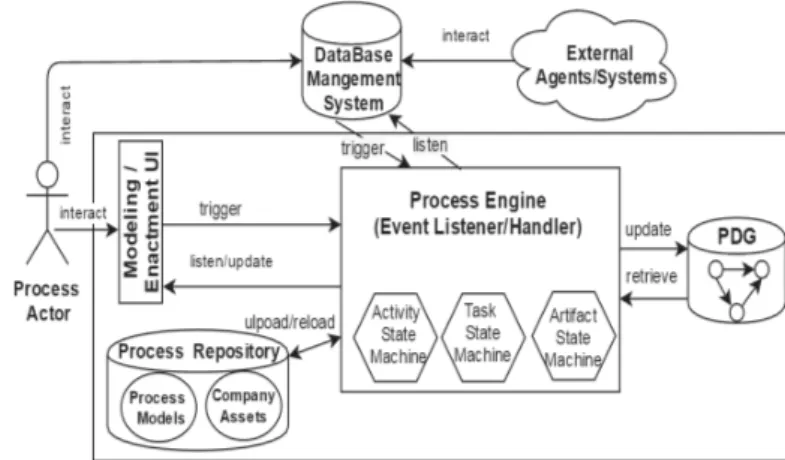
Figure 4 shows our Bottom-up Artifact-centric Process Envi-ronment (BAPE) comprising the following components:
Fig. 4: Architecture of BAPE
1) Modeling/Enactment UI: This component provides in-terfaces that allow process actors to interact with the process environment during the modeling and enacting phases. The modeling interface enables process actors to define company assets and model the fragments of their processes then store
them into the Process Repository. The enactment interface enables process actors to manage their activities and tasks (e.g., create activities, start and complete tasks, etc.).
2) Database Management System (DBMS): We suppose that resources (e.g., process actors, tools, etc.) and working artifacts are externally managed by each company proper tools. However, those external tools use a central DBMS which is connected to BAPE. This connection makes the process environment being aware of any events changing the state of artifacts and resources in the external systems.
3) Process Dependency Graph (PDG): This component stores the information of running processes managed by BAPE. PDG is progressively updated by the process engine to reflect always the current state and the global view of the system at run-time. Hence, PDG is a source of information for the process engine to coordinate and synchronize processes.
4) Process Engine:This component is in charge of enacting and synchronizing the processes managed by BAPE. The be-havior of process engine is based on state machines specifying the life-cycles of activities, tasks and artifacts. These state machines pilot the engine by defining the list of listened events triggered by users or external systems along with engine’s actions to handle these events to update the PDG and make process enactment progress.
In the following, we present how the PDG and the artifact-centric process engine enable process execution and synchro-nization in a flexible way.
B. Process Dependency Graph (PDG)
PDG is our solution to monitor process elements’ instances as well as the relations among them [13]. As process models are fragmented in our system, the role of PDG is not only storing runtime information but also establishing the global view of the system from separate process fragments. For this purpose, PDG is defined as a directed and typed graph where each PDG element refers to its defining process element in our SPML language. In this way, PDG nodes represent process element instances and PDG edges represent the relations between them. Representing the behavioral aspect of the process, each PDG node has the property describing its current state in the system. The instantiation of a process fragment is then a creation of PDG’s nodes and edges conforming to the elements specified in the fragment’s model. The execution of process concerns updating the PDG progressively.
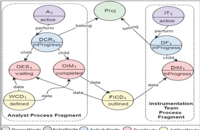
Figure 5 illustrates an extraction of the PDG representing a snapshot of the system corresponding to the execution of the Modify Testbench Wiring process in the project Pro j. This snapshot includes only the fragments of Analyst and
Instrumentation Team performed respectively by the actors
A1 and IT1. The PDG shows the current state of process
elements and the relations among them. The dependencies among tasks, both inside or among process fragments, can be established based on their exchanged artifacts. For example, in the activity Detail Change Requirement DCR1, the task Outline Instrumentation Model OIM1 produced the artifact FICD1 in the state outlined; the task Define Instrumentation Model DIM1is modifying an outlined FICD1and will produce
the defined FICD1 which will be used by the task Define Electrical Specification DES1. Thus, OIM1 has to finish so
that DIM1can start and DIM1has to finish so that DES1can
finish.
Thanks to the information provided by the external systems which manages company’s resources and data, the PDG’s
ActorNodes and ArtifactNodes can be created and updated. When process actors enact process’s activities and tasks, the corresponding ActivityNodes and TaskNodes will be added progressively into the PDG and the edges among the concerned nodes will be established or updated.
Fig. 5: A Snapshot of PDG
C. Artifact-centric Task Synchronization
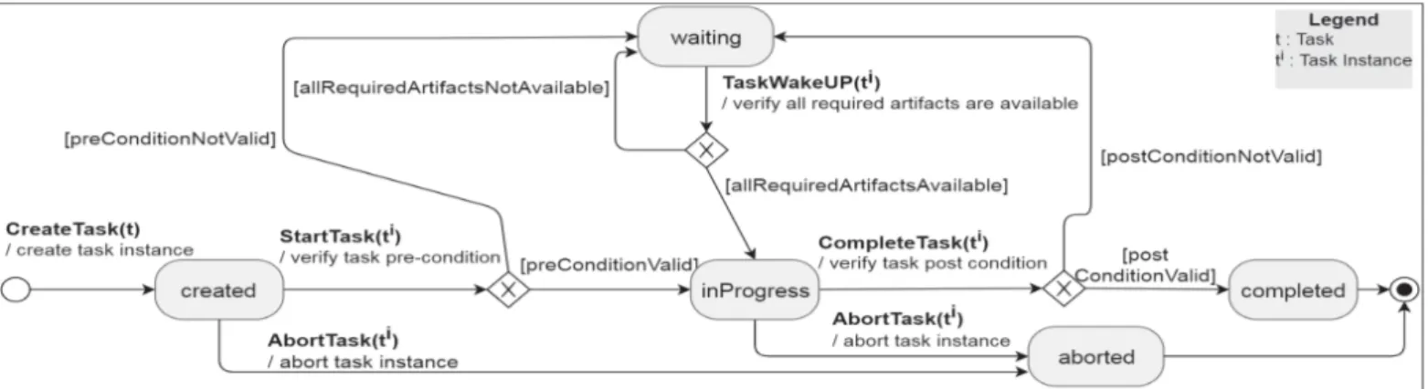
To manage the life-cycle of tasks, we adopt a state machine inspired from the standard WS-HumanTask Specification [8] as illustrated in Figure 6.
This state machine pilots the process engine in creating and updating the TaskNodes of the PDG when a task event is triggered by process actors through their Enactment UI. For each task event, the process engine verifies the condition of the required transition to enable or refuse the transition. If the transition is accepted, the process engine updates the concerned PDG TaskNode and its parameters by using the predefined actions for the transition and then allows the actor to perform task. If the transaction is refused, the demanding task has to wait until another event validates the transition condition. In this way, the process engine synchronizes the execution of different process actors’ tasks.
Note that in conventional process engines, the condition of a transition between task’s states is principally based on work-sequence relations defined among tasks. This solution cannot be applied to our process engine as we do not describe the work-sequence relations among tasks in process models. Instead of work-sequence relations, our process engine uses artifacts as the main source to enable the transitions between task states.
The conditions of two most important transitions to start and to finish a task are defined in the task’s model as pre-and post-conditions that specify respectively the required state of the task’s input and output artifacts. The process engine verifies the pre/post conditions of a task instance in the PDG by checking if the states of the concerned ArtifactNodes are the required ones. If the pre-condition is satisfied, the process engine updates the TaskNodes’s state from created to
inProgress. If not, the TaskNode will be put in waiting state to wait until the required input ArtifactNode is available. The post-conditions are verified similarly. For instance, Figure 5
Fig. 6: Task State Machine
illustrates the situation where the task DES1is waiting for the
artifact FICD1in a state de f ined which is required to produce
the artifact Electrical Specification.
V. INDUSTRIAL CASE STUDY
The experiment presented in this paper is a simplified version of a real case study conducted in the context of the project ACOVAS. We carried out our evaluation in two phases of modeling and enactment for the process described in Figure 1. We applied a simple setup of the scenario presented in Section II for a project including five process actors as one actor in each team. Our evaluation has been carried out using top-down process environments jBPM [3] and AristaFlow [1], which use BPMN [10] as their modeling language, and our prototype BAPE.
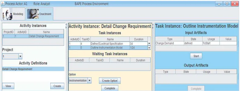
In order to efficiently manipulate the PDG, we used the graph database system Neo4j [7], which excels at managing highly connected, rapidly changing data thanks to its powerful traversal framework. Our framework is based on the assump-tions that a central graph database, a central resource repository and an application server (e.g. jBOSS) are provided to support process management in a distributed environment. Figure 7 shows the BAPE Enactment UI of role Analyst.
Our assessment on modeling phase is based on the required roles to participate into two sub-phases process modeling and process deployment. Our evaluation on enactment phase is based on the required degree of process completeness to enable the synchronization of activities and tasks.
The result of our modeling and enactment evaluations is presented in the Table I.
TABLE I: Modeling and Enactment Phases Evaluations
jBPM AristaFlow BAPE Modeling designerprocess actor designerprocess actor process actor Deployment designer
process actor
designer
process actor process actor Synchronization complete-defined complete-defined partial-defined
As learned from our experience, jBPM and ArtistaFlow require the participation of both process actors and process designers to model and deploy the process. By proposing SPML with a user-friendly modeling interface developed in BAPE, process actors can conveniently model their executable processes.
Regarding process synchronization, both jBPM and ArtistaFlow require that the whole process is modeled before enactment so that the process engine can know how to syn-chronize and coordinate the activities. As a main advantage, BAPE can enact and synchronize a partially defined process where some process fragments are missing.
VI. RELATEDWORK
The lack of adoptation by end-users has been recognized as a major problem of existing process environments in SSE [6]. To deal with this issue, many researches aim at integrating end-users into process management life-cycle in order to suit process actors needs [11], [2], [12].
Front et al. [2] propose a participative modeling approach named ISEA that allows process actors to collaborate in a centralized way to improve the process elicitation. Oppl [11] shares the same idea as ours on eliminating the work-sequence flows among activities and fragmentating of process models. However, both works lack enactment support in their solution. They propose the transformation of process models into BPMN [10] that requires the efforts of process actors and process designers to model the behavioral aspect of their processes and then validate and deploy the process into target process environment.
Stoitsev et al. [12] develop a collaborative task management tool CTM (as add-in to Microsoft Outlook) to enable end-users creating hierarchical to-do task lists. Tasks can be delegated over email exchange. Tracking of email exchanges on task delegation integrates the end-user’s personal to-do list to overall Task Delegation Graphs (TDG). TDGs represent weakly-structured process models that are captured snapshots of the actual process enactment. Like us, they apply a graph structure for the re-composition of the global model, but the work-sequence relations among tasks are defined as a suggestion based on the time of tasks processing changes.
We share the same vision as PHILharmonicFlows [5] and PET [4] about the significant role of artifacts in process modeling and enacting. Kuhrmann et al. [4] propose a solution to ease the process deployment for process actors by transforming the process models from SPEM into the artifact format of the project tools (e.g., Team Foundation server, SharePoint and OfficeWord). Their solution eases the deployment of processes into some specific development tools
Fig. 7: Enactment UI of Analyst
but does not consider the process synchronization. Kunzle et al. [5] emphasize on the integration of process and data to offer more flexible and efficient process enactment through the PHILharmonicFlows framework. They address modeling and enactment of object-aware processes. Object types and object relations are defined in a data model, while object behavior are expressed in terms of a process whose execution is driven by object attribute changes. However, their work adopts the top-down approach that requires a global view of process model before enactment.
VII. CONCLUSIONS
To avoid the gap between a process model at high-abstraction level and its execution in real projects, we proposed an end-user approach that allows process actors to model and enact the process that they perform in practice.
We developed a prototype for our process environment BAPE that supports process actors in modeling and enacting their process fragments. The first contribution of this work is the simple process modeling language SPML which offers structural and fragmented process modeling to process actors. The second contribution is an artifact-centric process engine that enables enacting and synchronizing of processes which are defined, even partially, by several fragments. Our solution makes the process modeling simpler and offers more flexibili-ties to enactment by giving more freedom to process actors in controlling their activities.
The first feedback of our industrial partners is rather positive thanks to the end-user friendly characteristic of our approach. As future work, we investigate a solution to integrate process actor’s working tools to BAPE in order to offer them a consolidated environment to manage their daily activities.
VIII. ACKNOWLEDGEMENT
Part of this research has been supported by the French research project FUI ACOVAS which associates AIRBUS,
GFI, IRIT, LIEBHERR, NEXEYA, PROMETIL, S2C and ZODIAC. We are grateful to our industrial partners who have helped us on developing the case studies for our research and on validating our prototype.
REFERENCES [1] AristaFlow. http://www.aristaflow.com/.
[2] A. Front, D. Rieu, M. Santorum, and F. Movahedian. A participative end-user method for multi-perspective business process elicitation and improvement. Software & Systems Modeling, pages 1–24, 2015. [3] JBoss. jbpm, http://www.jbpm.org/.
[4] M. Kuhrmann, G. Kalus, and M. Then. The process enactment tool framework-transformation of software process models to prepare enactment. Sci. Comput. Program., 79:172–188, Jan. 2014.
[5] V. K¨unzle and M. Reichert. Philharmonicflows: towards a framework for object-aware process management. Journal of Software Maintenance and Evolution: Research and Practice, 23(4):205–244, June 2011. [6] R. Matinnejad and R. Ramsin. An analytical review of
process-centered software engineering environments. In IEEE 19th International Conference and Workshops on Engineering of Computer-Based Systems, ECBS 2012, Novi Sad, Serbia, April 11-13,2012, pages 64–73, 2012. [7] Neo4j. Neo4j website : http://www.neo4j.com.
[8] OASIS. Web Services Human Task (WS-HumanTask) Specification Version 1.1, August 2010.
[9] OMG. Software & Systems Process Engineering Metamodel Specifi-cation (SPEM) Version 2.0, Apr. 2008.
[10] OMG. Business Process Model and Notation (BPMN) Version 2.0.2, Dec. 2013.
[11] S. Oppl. Articulation of work process models for organizational alignment and informed information system design. Information & Management, 53(5):591 – 608, 2016.
[12] T. Stoitsev, S. Scheidl, F. Flentge, and M. M¨uhlh¨auser. From personal task management to end-user driven business process modeling. In Proceedings of the 6th International Conference on Business Pro-cess Management, BPM ’08, pages 84–99, Berlin, Heidelberg, 2008. Springer-Verlag.
[13] H. N. Tran, M. Hajmoosaei, C. Percebois, A. Front, and C. Roncan-cio. Integrating run-time changes into system and software process enactment. Journal of Software: Evolution and Process, 28(9):762– 782, 2016.