an author's
https://oatao.univ-toulouse.fr/26936
https://doi.org/10.1016/j.compositesa.2019.105731
Rahmé, Pierre and Moussa, P. and Lachaud, Frédéric and Landon, Yann Effect of adding a woven glass ply at the exit
of the hole of CFRP laminates on delamination during drilling. (2020) Composites Part A: Applied Science and
Manufacturing, 129. 105731. ISSN 1359-835X
E
ffect of adding a woven glass ply at the exit of the hole of CFRP laminates
on delamination during drilling
P. Rahme
a,⁎, P. Moussa
a, F. Lachaud
b, Y. Landon
baLebanese University, Faculty of Engineering, Mechanical Engineering Department, P.O. Box : 27622319, Roumieh, Lebanon
bUniversité de Toulouse, INSA, UPS, Mines Albi, ISAE, ICA (Institut Clément Ader), Bât 3R1, 118 Route de Narbonne, F-31062 Toulouse cedex 9, France
Keywords: Drilling
Composite materials Ply of glass/epoxy Delamination Critical thrust force Pilot hole
A B S T R A C T
Composite materials are increasingly used in the aeronauticalfield. The assembly of structures requires usually drilling of composite parts. Drilling of composite materials generates defects, mainly delamination at the exit of the hole. This major defect diminishes the structure strength. Delamination is directly related to the drilling thrust force. Minimizing this force reduces the defects. Adding a woven glass ply at the exit of the hole is found to be another adequate solution to reduce the defects. In this paper, the drilling of carbon/epoxy thick composite structures with a woven glass ply at the exit of the hole is considered. An analytical model is developed to determine for a given tool geometry the critical delamination forces as function of the number of non-drilled plies remaining beneath the tool. The results are validated experimentally. These results show that adding a woven glass ply at the exit of the hole reduces delamination.
1. Introduction
The bolted assembly of two composite carbon/epoxy plates (or one composite and another metallic) requires drilling of holes using cutting tools. The twist drill is the most widely used drilling tool, with its main parts: the chisel edge (dead center) and the cutting edges. The drilling by removing material of the composite structures generates defects at the entry of the hole, on the wall and at the exit of the hole[1–3]. These defects detract from the strength of the structure. The major defect, called delamination, caused by the drilling is located at the exit of the hole[1–5]. The chisel edge of the twist drill cannot cut the material, due to its sharpening and zero cutting speed at the center, but it ex-trudes it[6]. This creates a normal stress on the plane of the plate which leads to the separation of the plies and therefore delamination at the exit of the hole[7]. The delamination of a composite structure corre-sponds to a cohesive failure of the matrix and a separation of the plies. Delamination of fibers is an important problem when machining a composite material. Hocheng et al.[5]defined the critical delamination
force as the smallest force which causes the appearance of the first delamination. Then, to eliminate delamination when drilling, the ap-plied thrust force must not exceed the critical thrust force of the non-drilled thickness for the composite plate. When drilling, the used cut-ting conditions must be less than the critical conditions corresponding to the critical delamination force.
At the exit of the hole, the axial force of penetration imposed by the tool (FZ) tends to bend the last plies. This can cause the cohesive failure
of the matrix until the tearing of the last ply and the breaking of the fibers, causing delamination of the last plies[8]. This delamination at the exit of the hole, which is considered to be the major defect, is therefore influenced by the thrust force (FZ) [9,10]. Several studies
[4,5,11,12,13]have been carried out on the modeling of the critical axial force of delamination at the exit of the hole. As per Piquet et al.
[4], different tool geometries can effectively reduce delamination by
decreasing the thrust force (FZ). Also, the axial force and the
delami-nation depend significantly of the state of wear of the tool[14]. This state of wear is strongly dependent on the material of the drill. Finally, the use of special tools as well as the adjustment of drilling and reaming conditions can greatly reduce delamination[15–17]. Moreover, Rahme et al.[18,19]state in their experimental observations that defects at the exit of the plate are considered as being the major defects and the length of cracks between the last plies is always important. They showed that the cracks arefirst initiated under the chisel edge and propagated through the plies under the cutting edges. The critical de-lamination forces are then these which correspond to the initiation and propagation of cracks at the exit of the plate. According to Fernandes et al.[20]and Won et al.[21], the delamination at the exit results in the separation of the last plies according to the cracks opening mode I. On the other hand and for the effect of anisotropy on the critical force,
https://doi.org/10.1016/j.compositesa.2019.105731
⁎Corresponding author.
the isotropic material has a higher delamination resistance than the orthotropic material, according to Rahme[18]. The anisotropic com-posite material can then be delaminated by applying a lower axial force. Therefore, the anisotropy has a significant influence on the cri-tical delamination effort. That is why, a solution to minimize the de-lamination is to add a taffeta fabric ply at the entrance and the exit of the composite plate.
In this paper, the drilling of carbon/epoxy thick composite plates with a woven glass ply at the exit of the hole is considered. A taffeta woven glass fabric is used. This glass fabric has a better resistance to delamination and eliminates, at the same time, the galvanic couple between the composite and the metal structure during assembly, if any. The study of drilling composite materials with a woven glass ply at the exit of the hole has not been developed yet. An analytical model that takes into account the added glass fabric ply at the exit of the hole is presented in this work. This model calculates the critical thrust force for a given number of non-drilled plies remaining under the drill, when drilling composite plate with a glass fabric ply at the exit. Finally, ex-perimental tests are performed to validate both models and the results are compared and discussed.
2. Modelling of the critical thrust force at delamination
When drilling a laminate, the last plies at the exit of the hole should be modeled to determine the critical thrust force at delamination. In this paper, at the exit, the remaining non-drilled plies including the glass/epoxy woven fabric are modeled as thin circular orthotropic la-minate, without back-up support at the exit. This laminate should be subjected to the load induced by the drill. This loading is directly re-lated to the cutting tool action on the material during drilling. This loading is considered axisymmetric since the cutting speed is much bigger than the feed rate speed of the drill. In this paper, a conventional twist drill of diameter 16 mm, made of tungsten (K15), is used. It is a tapered relief twist drill without thinning of the chisel edge [DIN 1897]. The length of the chisel edge of this drill is 3.9 mm. According to Rahme et al.[3,6], the cracks are initiated under the chisel edge and propa-gated under the cutting edges. More, based on the observations pre-sented by Rahme et al.[19], a visible deflection of the plate located
under the drill is shown in the direction of the drill axis. This deflection results of absence of any resistant moment. Consequently, when the chisel edge is approaching the exit of the plate, the part remaining under the drill is modeled by a simply supported thin circular laminate, of diameter equal the length of the chisel edge (2a), subjected to a uniformly distributed load, as shown inFig. 1. When the chisel edge exits out of the plate, the effect of the cutting edges is modeled by a simply supported laminate, of diameter slightly greater than the length of the chisel edge (2b), with a pilot hole at the center of diameter equal the length of the chisel edge, as shown inFig. 2. A diameter (2b) of 6 mm is taken in this study. Indeed, an assumption of propagation of cracks is taken at the beginning of the cutting edges, around the boundaries between the chisel edge and the cutting edges. This as-sumption has been taken based on observations of cracks propagation using a high speed camera[19].
Using the principle of conservation of the energy for the plate and the theory of plates and shells developed by Timoshenko and Woinowsky-Krieger[22], the critical thrust force at delamination cor-responding to the considered loading and boundary conditions, for the effect of the chisel edge without pilot hole, is found as:
= + F πD ϑ G D 8 ( 1) 2 ' C rθ IC 1 (1) With: = + + + D 1 D D D D 8(3 11 2 12 4 66 3 22) (2) And = + + − + + D' D(ϑ2rθ 14ϑrθ 13) 3(D11 2D12 D22) (3) ϑrθis the poisson’s ratio in polar coordinates and Dijare found to be
function of the stiffness matrix of the laminate as:
∑
⎜ ⎟ = ⎛ ⎝ − ⎞ ⎠ = − D Q Z Z | | ( ¯ ) 3 ij k n ij k k k 1 3 1 3 (4) where Qijare the stiffness coefficients of the laminate located under thedrill. Zkis the position of the ply k through the thickness from the mean
plane of the laminate.
The critical energy release rate corresponding to crack opening in mode I, GIC, is experimentally found using the double cantilever beam
(DCB) of international standard[23]. This energy corresponds to the interface glass woven and carbon unidirectional lamina (GFRP/CFRP) for the last ply (GICCG) and to the interface carbon/carbon (CFRP/CFRP)
for the plies above (GICCC).
The same method is used to determine the effect of the cutting tools
Fig. 1. Equivalent model of the laminate with glass ply at the exit for the part located under the chisel edge.
Fig. 2. Equivalent model of the laminate with glass ply at the exit for the part located under the cutting edges.
when the cracks start to propagate. The critical thrust force is analyti-cally also found as:
= + − − + + F πD a b a b ϑ aG K L M 8 ( ) ( ) ( 1) 3 ( ) C rθ IC 2 2 2 2 (5) where: ⎜ ⎜ ⎟ ⎟ = ⎛ ⎝ ⎛ ⎝ − ⎞ ⎠ + − + ⎞ ⎠ + ⎛ ⎝ ⎞ ⎠ K a Db Da b a Z b b a 72 2 3 (ϑ 1) 4 3 (ϑ 1) (1 ϑ ) ln rθ rθ rθ 3 2 2 2 3 5 2 2 (6) = − + + − + + − + + + ⎛ ⎝ ⎞ ⎠ L ab a b Db ab Z Da b a Z b a 24 ( )(1 ϑ ) ((3ϑ 2ϑ 5) ( 1 ϑ )(3 ϑ ) ')ln rθ rθ rθ rθ rθ 3 2 2 2 2 3 2 2 3 (7) = + − + − − + + M (a b) (2a b) (2C b C b C b 2C b C b a C) 1 5 2 4 3 3 4 2 5 2 4 (8) = − − + + + Z D(ϑrθ2 2ϑrθ 3) D11 2D12 D22 (9) = − − + + + Z' D(ϑ2rθ 2ϑrθ 7) 2D11 4D12 2D22 (10) = − ⎛ ⎝ + + + + + ⎞⎠ C 7 D D D D 2(ϑ 1) (ϑ 2ϑ 1) 3 7 6 7 3 7 rθ rθ rθ 1 2 2 11 12 22 (11) = ⎛ ⎝ + + ⎞ ⎠ − C 13aD ϑ 6ϑ 53 13 (ϑ 1) rθ rθ rθ 2 2 2 (12) = + − − − + − − − + − − − C a D D D D D D D D D D D D D ( ϑ (46 9 18 9 )ϑ (96 30 60 30 )ϑ 49 9 18 9 ) rθ rθ rθ 3 2 4 11 12 22 2 11 12 22 11 12 22 (13) = + + − C4 Da3(ϑrθ2 8ϑrθ 7)(ϑrθ 1)2 (14) = ⎛ ⎝ + ⎛ ⎝− + + + ⎞⎠ + ⎛ ⎝− + + + ⎞ ⎠ − + + + ⎞ ⎠ C a D D D D D D D D D D D D D 7 2 ϑ 62 7 15 7 30 7 15 7 ϑ 96 7 18 7 36 7 18 7 ϑ 41 7 15 7 60 7 15 7 rθ rθ rθ 5 4 4 11 12 22 2 11 12 22 11 12 22 (15) 3. Experimental results
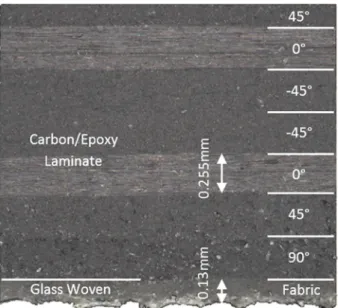
Composite carbon/epoxy laminates of thickness 10.33 mm are used in this section in order to experimentally validate the models. One la-mina of glass/epoxy woven fabric is added to the carbon/epoxy lami-nate at the exit of the hole. The stacking sequence of the used quasi-isotropic laminate is [90°, 45°, 0°,−45°]S5. The glass woven fabric
la-mina has a thickness of 0.13 mm and the unidirectional carbon/epoxy lamina (T700/M21) has a thickness of 0.255 mm and a surface mass of 268 g/m2, as shown inFig. 3. Adding a woven glass ply at the exit of the
laminate may reduce the delamination. At the same time, and in the case of the assembly of carbon composite laminate with another me-tallic plate (like aluminum alloys), adding this glass ply may also reduce the galvanic corrosion. Finally, this glass ply contributes to isolate and protect the airplanes against the lightning strikes.
The critical energy release rate is needed in the modelling part. For this purpose, experimental tests are conducted according to
Fig. 3. Stacking sequence and thickness of each lamina of the used laminate.
G
ICInitiation
G
ICPropagation
international standard [23]using double cantilever beam (DCB) spe-cimen. The critical energy release rate in mode I (opening mode) is found for all cases: (i) cracks between unidirectional carbon/epoxy, (ii) cracks between glass/epoxy woven and (iii) cracks between unidirec-tional carbon/epoxy and glass/epoxy woven (GFRP/CFRP,Fig. 4). As shown inFig. 4, the initiation phase is identified in the beginning of the
cracks growth. However, after the initiation phase of the crack, the propagation of the crack is shown with a constant value of the energy (i.e, the plateau on thefigure). As shown, the values of the critical rate energy corresponding to the initiation and propagation of cracks be-tween unidirectional carbon/epoxy CFRP and glass/epoxy woven GFRP are 338 J/m2and 402 J/m2, respectively.
The mechanical properties of the used unidirectional carbon/epoxy and woven glass/epoxy are also experimentally found and presented in
Table 1.
To validate the proposed analytical model in the previous section, experimental tests have been realized. To measure the critical thrust force, punching tests are performed. These static punching tests are
considered to be the suitable method to experimentally identify dela-mination as a function of the remaining non-drilled plies. Indeed, it is very difficult to identify delamination during drilling. Several blind holes are drilled to be used for the punching tests. The number of non-drilled carbon plies remaining under the drill varies from zero to six. When the number of non-drilled carbon plies is zero, the glass woven fabric ply is only punched. A standard conventional twist drill, without web thinning, of diameter 16 mm and of point angle 132°, is used to drill the blind holes. The length of the chisel edge of this drill is 3.9 mm. A cylindrical punch of 3 mm diameter is used for the punching tests without pilot hole. Also, to validate the effect of the cutting edges, a pilot hole of diameter 3.9 mm is taken and another cylindrical punch of 6 mm diameter is used for the punching tests. This diameter is taken based on the experimental observations showing that the cracks pro-pagate just after they have been initiated under the chisel edge.
The pilot holes and the blind holes are drilled using a 5-axis CNC Machine with a rated power of 25 kW and a maximum spindle speed of 18,000 RPM. Also, the punching tests are performed using the same machine. The punching force is recorded using a Kistler dynamometer 9257B, operated with a frequency of 1000 Hz and a maximum sup-ported axial load of 15 kN.Fig. 5shows the used experimental setup for punching tests, as well as the used laminate, the twist drill, the load cell and the punch. The following sequence is taken to perform the punching test for a given number of non-drilled plies: (i)fix the lami-nate on the used setup, (ii) drilling a blind hole with a given number of non-drilled plies using a twist drill, (iii) replace the twist drill by the punch, and (iv) punching quasi-static test using a speed of 1 mm/min. The process is repeated by changing the expected hole location and the number of non-drilled plies.
Table 1
Mechanical Properties of the used composite materials.
Material E11(GPa) E22(GPa) E33(GPa) G12(GPa) G13(GPa) G23(GPa) ν12 ν13 ν23 G1CI(J/m2) G1CP(J/m2)
Carbon/epoxy UD (CFRP) 135 8 8 4.8 4.8 3.2 0.31 0.31 0.36 400 430 Glass/epoxy woven (GFRP) 21 21 10 4.8 4.8 3 0.05 0.05 0.3 373 530 Interface CFRP/GFRP – – – – – – – – – 338 402
Load cell
Twist drill
Composite
laminate
Punch
Fig. 5. Experimental punching tests using CNC machine and load cell.
Fig. 6. Example of recorded punching thrust force corresponding to the initiation of cracks for 4 delaminated plies without pilot hole, beginning of non-linear curve, value = 880 N.
4. Results and discussion
Fig. 6shows an example of the thrust force graph recorded during a punching test for four non-drilled carbon laminae remaining under the drill, without pilot pole. As shown on the figure, the corresponding critical thrust force at delamination measured experimentally is 880 N. This value is identified as the first point where the curve starts to lose its linearity. This corresponds to the initiation of cracks under the chisel edge. However, based on the non-linearity method, it is not easy to identify, in an accurate way, the critical thrust force due to the initia-tion of cracks. An ultrasonic sensor may be used in future works to identify the initiation of cracks. The significant drop in force corre-sponds to the failure offibers due to bending, at the exit of the hole. Varying the number of non-drilled laminae remaining under the drill from zero to six carbon/epoxy plies, the critical thrust force at dela-mination is experimentally recorded for each test, in the same manner. The critical thrust force at delamination is plotted as function of the delaminated laminae remaining under the drill, for both analytical and
experimental cases, as shown onFig. 7. On thefigure, a zero lamina under the drill corresponds to the punching of the glass woven ply only. The maximum relative error found between the analytical model and the experimental results is about 20% for the carbon laminate. This maximum error can be considered acceptable since the analytical model is conservative. However, for the punch of the woven glass ply, a re-lative error of about 75% is found. This high error could be due to the non-accurate method of the identification of the cracks initiation, which is based on the identification of the beginning of the non-linearity of the punch force curve. More, the developed analytical model is sensitive to the thickness and the critical energy release rate. Any error in the de-termination of these two parameters results an amplification of the error in the critical thrust force.
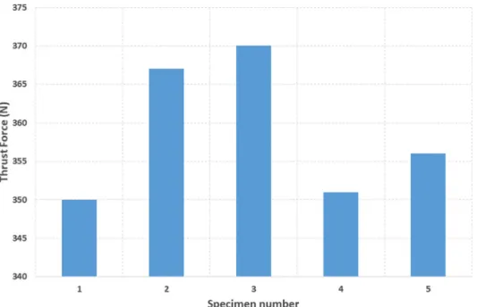
Several punching test have been also performed to verify the re-peatability of the tests.Fig. 8showsfive punching repeatability tests for five specimens corresponding to two non-drilled laminae remaining under the drill. A maximum relative error of 3% is found. This error is small and is assumed to be acceptable.
Fig. 7. Comparison of the critical thrust force of the analytical model with the experimental results without pilot hole.
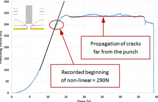
The same punching tests are repeated on another blind holes with pilot hole. Pilot holes of diameter 3.9 mm, equal to the length of the chisel edge, are pre-drilled. Fig. 9shows an example of the recorded punching thrust force on blind hole with pilot hole for two delaminated plies remaining under the punch. Same, the critical thrust force corre-sponding to the propagation of cracks under the drill is identified by the non-linearity of the force curve. For the taken example, a critical thrust force of 290 N is found. More, a plateau of the propagation of cracks is found onFig. 9. This plateau shows the propagation of cracks far from the punch. The assumption of the initiation of cracks under the chisel edge and the propagation of cracks under the cutting edges is validated.
Fig. 10shows the comparison of the analytical and the experimental critical thrust force, for a number of carbon plies varying from 1 to 6. A maximum relative error of 13% is found for the carbon laminate when two plies are remaining under the punch. When the woven glass ply is only remaining under the punch, an error of 60% is found. For the same reasons explained before for the case without pilot hole, the high value
of the relative error can be explained. However, the critical thrust forces of the analytical model are always conservative with respect to the experimental results.
The effect of adding a glass woven ply at the exit of the hole is however shown when comparing the critical thrust force at delamina-tion.Fig. 11shows the analytical ratio of the critical thrust forces with a woven glass ply and without this ply, as function of the number of delaminated plies. Thefigure shows that when adding a woven glass ply at the exit of the hole, the critical thrust force at delamination is am-plified. The ratio of amplification varies for this case between 1. 5 and 1, approximately, for both cases of drilling with and without a pilot hole. This result shows the importance of adding a woven glass ply on the critical thrust forces at delamination. Increasing the critical thrust force at delamination reduces the defects at the exit of the hole. In future works, the critical cutting conditions at delamination should be found and experimental tests using these values should be performed to validate these results, for a given couple of laminate/tool.
Fig. 9. Example of recorded punching thrust force corresponding to the propagation of cracks for 2 delaminated plies with pilot hole, beginning of non-linear curve, value = 290 N.
5. Conclusions
Drilling of composite laminates generates delamination at the exit of the hole. Delamination reduces the strength of the structure. A solution to reduce delamination is to add a glass woven fabric ply at the exit of the hole. In this paper, drilling of carbon/epoxy composite laminate with one glass woven fabric ply at the exit of the hole is studied. An orthotropic analytical model is developed to determine the critical thrust force at delamination as function of the remaining non-drilled plies under the tool. The proposed analytical model is validated by experimental punching tests. The analytical and experimental results are closed. The analytical model is always conservative. These results show that adding a glass woven fabric ply at the exit of the hole in-creases the critical thrust force and then decrease delamination effect. CRediT authorship contribution statement
P. Rahme: Conceptualization, Methodology, Software, Validation, Formal analysis, Investigation, Data curation, Visualization, Supervision, Project administration, Funding acquisition.P. Moussa: Software, Validation, Formal analysis, Investigation, Data curation, Visualization.F. Lachaud: Conceptualization, Methodology, Resources, Supervision. Y. Landon: Conceptualization, Methodology, Resources, Supervision, Project administration, Funding acquisition.
Acknowledgements
This work was carried out within the context of the working group Manufacturing 21 which gathers 18 French research laboratories. The topics approached are:
•
The modelling of the manufacturing process,•
The virtual machining,•
The emerging of new manufacturing methods.This project has been funded with support from the Lebanese University.
References
[1] Rahme P, Landon Y, Lachaud F, Piquet R, Lagarrigue P. Delamination-free drilling
of thick composite materials. Compos A Appl Sci Manuf 2015;72:148–59. [2] Rahme P, Landon Y, Lachaud F, Piquet R, Lagarrigue P. Drilling of thick composite
materials using a step gundrill. Compos A Appl Sci Manuf 2017;103:304–13. [3] Rahme P, Landon Y, Lachaud F, Piquet R, Lagarrigue P. Study into causes of damage
to carbon epoxy composite material during the drilling process. Int J Mach Mach Mater 2008;3(¾):309–25.
[4] Piquet R, Ferret B, Lachaud F, Swider P. Experimental analysis of drilling damage in thin carbon/epoxy plate using special drills. Compos A 2000;31:1107–15. [5] Hocheng H, Tsao CC. The path towards delamination-free drilling of composite
materials. J Mater Process Technol 2005;167:251–64.
[6] Rahme P, Landon Y, Lagarrigue P, Lachaud F, Piquet R. Drilling thick composite materials using large diameter drills. Int. J. Mach Machin Mater 2011;10:202–11. [7] Hocheng H, Tsao CC. Comprehensive analysis of delamination in drilling of com-posite materials with various drill bits. J Mater Process Technol 2003;140:335–9. [8] Hocheng H, Dharan CKH. Delamination during drilling in composite laminates.
ASME J Eng Ind 1990;112:236–9.
[9] Tsao CC, Hocheng H. The effect of chisel length and associated pilot hole on dela-mination when drilling composite materials. Int J Mach Tools Manuf
2003;43:1087–92.
[10] Langella A, Nele L, Maio A. A torque and thrust prediction model for drilling of composite materials. Compos A 2005;36:83–93.
[11] Rahme P, Landon Y, Lachaud F, Piquet R, Lagarrigue P. Drilling of thick composite material with a small-diameter twist drill. Int J Adv Manuf Technol
2015;76:1543–53.
[12] Rahme P, Landon Y, Lagarrigue P, Lachaud F, Piquet R. Analytical models of composite material drilling. Int. J. Adv Manuf Technol 2011;52:609–17. [13] Velayudham A, Krishnamurthy R. Effect of point geometry and their influence on
thrust and delamination in drilling of polymeric composites. J Mater Process Technol 2007;185:204–9.
[14] Fernandes M, Cook C, Alici G. Investigation of hole quality on drilling carbon composites with a‘one shot’ drill bit. SAE Int 2005.
[15] Hocheng H, Tsao CC. Analysis of delamination in drilling composite materials using core-center drill. 11th ICCE, Hilton Head, SC, USA. 2004.
[16] Furet B, Jolivel B, le Borgne D. Milling and drilling of composite materials for the aeronautics. Revue Internationale JEC Composites No 18. 2005. p. 41–4. [17] GOULEAU S., GARNIER S., FURET B.,“Faisabilité du perçage d’empilements
multi-matériaux de type aluminium/composites’’, 4ème Assises Machines et Usinage à Grande Vitesse– SYMAP-ENSAM – 8 et 9 Juin 2006 – Aix en Provence. [18] Rahme P. Thèse,‘‘Contribution à l’Etude de l’Effet des Procédés de Perçage-Alésage
sur l’Apparition du Délaminage dans les Structures Composites Epaisses’’. Laboratoire de Génie Mécanique de Toulouse, Toulouse: Université Paul Sabatier; 2008.
[19] RAHME P., LANDON Y., LACHAUD F., PIQUET R., LAGARRIGUE P. Perçage car-bone. Retrieved from:https://www.youtube.com/watch?v=fLelInglyK0. 2010. [20] Fernandes M, Cook C. Drilling of carbon composites using a one-shot drill bit. Part
II: empirical modeling of maximum thrust force. Int J Mach Tools Manuf 2005:1–4. [21] Won MS, Dharan CKH. Drilling of aramid and carbonfiber polymer composites.
Trans ASME, J Manuf Sci Eng 2002;124:778–83.
[22] Timoshenko S, Woinowsky-Krieger S. Theory of plates and shells. McGraw Hill; 1959.
[23] INTERNATIONAL STANDARD ISO 15024:2001. Fibre-reinforced plastic composites – Determination of mode I interlaminar fracture toughness, GIC, for uni-directionally reinforced materials. First edition, 2001-12-01.