To cite this version :
Martin Lopez, Eduardo and Lizy-Destrez,
Stéphanie
JumpSat Thermal and Mechanical Analysis.
In: 3rd IAA Conference on University Satellite Missions and Cube
Sat Workshop Satellites, 30 November 2015 - 4 December 2015
(Rome, Italy).
OATAO is an open access repository that collects the work of Toulouse researchers and makes it freely available over the web where possible.
This is an author-deposited version published in: http://oatao.univ-toulouse.fr/
Eprints ID : 14480
Any correspondance concerning this service should be sent to the repository administrator: [email protected]
IAA-CU-15-07-15
JumpSat Thermal and Mechanical Analysis
Eduardo MARTÍN LÓPEZ*, Stéphanie LIZY-DESTREZ**.
Abstract
In 2017, Swiss Space Systems (S3) is planned to operate un-manned suborbital space planes for launching small satellites. Within this scenario it was supposed to be launched JumpSat, a 3-Units CubeSat developed by ISAE-SUPAERO students, in col-laboration with ONERA, CNES, and TELECOM Bretagne. JumpSat mission was proposed by ISAE in 2012. Their main ob-jectives are both in-orbit technological demonstration and scien-tific research [1], through an elliptical Low Earth Orbit (LEO). The students are entirely involved in this mission, beyond both tech-nological and scientific objectives, from the early stage to the dis-posal. ONERA, in Toulouse, is developing Dynagrad, a radiation sensor for trapped particles in the Earth’s magnetic belts, espe-cially in the South Atlantic Anomaly (SAA), to improve the cur-rent models of radiation and their accuracy. Space qualification for a low-cost Star Tracker is under development at ISAE-SUPAERO. It will provide enough useful knowledge about system concept and software development for future small satellites missions. Another technological demonstration will accomplish a space qualification for the three-axis attitude control sub-system (AOCS) within the JumpSat mission. The acquired knowledge will help future Cu-beSats AOCS sub-systems., while other components are COTS. Moreover, a consortium with Thales Alenia Space, LAAS and ISAE-SUPAERO designed NIPMH (Nanosatellite Investigate Mi-crowave Photonic Hardware), an experimental payload based on opto-microwave technology. It would be embedded in a 3U Cu-beSat for testing different components sensitivity to radiations in
* ISAE-SUPAEROInstitut Supérieur de l’Aéronautique et de l’Espace, France, [email protected]
space, especially the optical fiber doped with erbium. Furthermore, due to the similarities among both missions, it was analyzed the possibility of the combination of both projects: NIMPH as an ad-ditional payload to JumpSat mission. It increases the mission du-ration up to a minimum of two years, with respect to French law for Space Operations (maximal mission duration: 25 years). This paper will focus on mechanical and thermal aspects that were com-pletely redesigned for JumpSat to comply with all requirements of both missions. From that point comes out the idea of building the first 6U CubeSat by ISAE-SUPAERO. As those studies are pre-sent in all design phases, they have important impact on the opti-mal architecture design within all the subsystems. Finally, temper-atures gradients are such a great problem in space that it is even more important with strong radiation doses, like for this mission. Then, thermal analysis for worst cold and hot cases is critical for analyzing the impact of the new payload within the mission.
Introduction
During the last decades there has been a great development of low cost and small satellites, especially in CubeSat projects.
The CubeSat concept was created in 1999 by Jordi Puig-Suari, from Polytechnic State University of California, and Bob Twiggs, from Stan-ford University. The objective was to allow the students design, build, test, and operate a satellite with capacities similar to the first satellite: Sputnik [1].
CubeSats are picosatellites (maximum mass equal to 1 kg). The standard 10x10x10 cm CubeSat is often called \one unit" or \1U". CubeSats are, usually, scalable along only one axis by 1U increments.
1. JumpSat Mission
JumpSat is a 3U CubeSat mission proposed in 2012 by ISAE-SUPAERO in collaboration with TELECOM Bretagne, Massachusetts Institute of Technology (MIT), Centre National d'Etudes Spatiales (CNES) and ONERA. The goals of this mission are:
Space qualification of a low-cost Star Tracker, which is currently under development by ISAE-SUPAERO students for future use in small satellite systems.
Mapping Earth radiation belt’s properties, especially over the South Atlantic Anomaly. ONERA is developing a directional ra-diation sensor called Dynagrad.
Space qualification of a three-axis attitude control sub-system of the JumpSat space segment. Then, the knowledge acquired with this mission will be reuse to develop generic CubeSats Attitude and Orbital Control Sub-System (AOCS).
In order to accomplish this main scientific and technological goals, the mission should fulfil some requirements:
Dynagrad is designed to measure particle’s distribution through the radiation belts (Van-Allen belts) of the Earth. Then it re-quires a variation in distance in order to acquire measurements at different altitudes. A great inclination, with a great distance between perigee and apogee, is required in order to accomplish the objectives all over the map.
The nanosatellites shall re-enter the Earth before 25 years ac-cording to the French Act on Space Operations -Loi relative aux Operations Spatiales (LOS): a French law that regulates the space debris mitigation. For this reason an elliptical orbit will help the objectives.
The nanosatellite shall pass fly over the same locations at the same time, simplifying the posterior comparison between the dif-ferent measurements. The orbit cannot be a sun-synchronous or-bit due to its needed eccentricity.
Spacecraft shall be the most of the mission duration in direct sunlight due to energy requirements. Power consumption will be very high because of both two payloads power consumption, in addition to the platform needs.
The selected orbit after mission analysis is: Semi-Mayor Axis: 7178,15 km Eccentricity: 0,0278
Inclination: 98,59º
Right Ascension of the Ascending Node (RAAN): 90 º Argument of Perigee: 0 º
Mean Anomaly: 0 º
2. NIMPH Mission
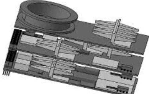
NIPMH stands for Nanosatellite Investigate Microwave Photonic Hard-ware. For next generation of telecommunication satellites, photonic tech-nologies and opto-microwave techtech-nologies are going to be innovative and essential. These optical components have been developed and verified for 10 year by space agencies, like as ESA or CNES, but the lack of in orbit experience feedback has slowed down the use of these technologies [2]. As a consequence, in-orbit test is the main goal of NIMPH mission. Tha-les Alenia Space proposed the design of an experimental payload de-signed by students and supervised by researchers. This mission will fulfill the in-orbit demonstration technology objectives based on opto-micro-wave technology. It would be embedded in a 3U CubeSat in order to test the sensitivity of the different components, especially the optical
fiber and their amplifiers, to the radiations in space. In Fig 1, they can be observed all three boards consisting of NIMPH payload: Detection Board, Source Board and (Erbium Doped Fiber Amplifier) EDFA.
Fig 1. Complete assembly design for a preliminary configuration of 2U size.
The goal of this mission is the measurement of the space radiations im-pacts on a set of microwave photonic components. The set of microwave and radiofrequency electronics components shall be operating all the or-bital life time and they have to be exposed to space radiations as much as possible. A sensor will measure in orbit the received radiation dose. In order to support payload main goals, the mission should fulfil some requirements:
The trajectory shall be an elliptic orbit between 400km and 10 000km, with an inclination high enough to maximize the irradi-ation.
The mission has to last at least two years in order to maximize the benefits of the mission objectives, and the technological demonstration.
The platform has to de-orbit in less than 25 years as well, com-plying with the LOS.
There will be only one ground segment in France with a 16dB directional antenna.
Finally, the selected orbit for NIMPH mission is described by at least the following parameters:
Semi-Mayor Axis: 7280 km Eccentricity: 0,075
3. Combining JumpSat and NIMPH Missions
JumpSat and NIMPH missions obviously share many parameters. As a consequence, researchers involved on both missions decided to analyze the feasibility to merge the two concepts, so as to reduce the cost. Two different designs were proposed: together on board a 6U CubeSat or separately in two 3U CubeSats. Main challenges lay in mission analysis and mechanical and thermal design.
The main difference between both missions is the duration. JumpSat lasts about 3-4 months and NIMPH lasts up to two years. For the com-bined mission it has been taken into account worst case duration, two years, in order to comply with NIMPH mission.
After mission analysis, orbital parameters have been chosen fulfilling the following requirements, from the combined mission JumpSat and NIMPH:
JumpSat will be operating at least 3-4 month NIMPH shall operate at least 2 years
The orbit shall be Low Earth Orbit (LEO)
The nanosatellite shall pass fly over the same locations at the same time
The nanosatellite shall fly over South Atlantic Anomaly
The orbit shall be elliptical in order to fly over Van Allen belts to measure the radiation dose (Dynagrad) and in-orbit demon-strate the opto-microwave technology (NIMPH)
The mission shall comply with the LOS: re-entry of any potential debris sent from France in less than 25 years
Then, the chosen orbital parameters for 6U CubeSat are defined by the following:
Semi-Mayor Axis: 7164,05 km Eccentricity: 0,04
Inclination: 98,54º
Right Ascension of the Ascending Node (RAAN): 90 º Argument of Perigee: 0 º
Mean Anomaly: 0 º
Those parameters have been used in mechanical and thermal studies.
CubeSat Design
using a Computer-Aided Design (CAD) tool: CATIA-V5. This 3D model is necessary to reach the best trade of accommodation for all subsystems. A massif, volumetric, and inertial analysis has been done thanks to this CAD model.
Once all the information related to every component, embedded the sat-ellite, was recollected and by identifying their dimensions and masses, either from their datasheets either from their developers themselves, their design started. This model is going to be useful to know the mass budget, inertias and volumetric capacities of the nanosatellite.
1. Platform 3U
First preliminary model just take into account the 3U platform as re-quired for JumpSat mission and their payload. For each component, their masses have been given. The mass is not a parameter you can tune directly in this software, the density is the value to enter in this CAD tool. Then, firstly you should design the volumetric component. Once you have its volume you set the density in CATIA according to the equation [1].
𝜌 =𝑚
𝑉 [𝐾𝑔/𝑚3] [1]
Where m is the mass, known from the data sheet for all Components off-the-shelf (COTS) components, and for the customized payloads such as the Star Tracker, Dynagrad, the three AOCS with the three reaction wheels, it was asked for to the people in charge of its development. Then, the V is the volume determined by the geometrical design of the compo-nent.
Once every component is designed separately are going to be assembled keeping in mind all the possible constraints. Since many components are still under development, and their specifications are not defined yet, some assumptions has been made:
CubeSat’s center of gravity shall be located as close as possible to the CubeSat geometrical center.
CubeSat’s center of gravity shall be located within the reaction wheels components, for a better natural stabilization.
JumpSat would have as many solar cells as possible all over the exterior faces due to extra-power requirements for all payloads Sun sensor shall not be located at –Z face, because it is not going
to face never the sun. JumpSat is going to have a –Z pointing to Earth
Star Tracker has to point into +Z direction, since the JumpSat is going to have –Z face pointing to Earth.
S-Band Patch Antenna has to point into -Z direction, because JumpSat is going to have –Z face pointing to Earth.
The components that are going to have a huge impact on the internal temperatures shall be located in different parts, and even in that scenario the temperature inside is too elevated, the PCBs would be deployable.
The payloads shall be far from the telecommunications subsys-tem in order to avoid any kind of interference.
Then, in order to create the complete assembly of JumpSat in accuracy, all the documentation from Innovative Solutions In Space (ISIS) [3], [4] was followed.
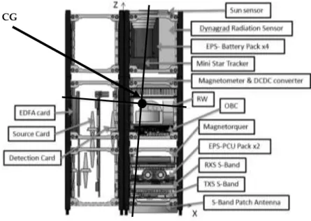
Fig 2. 3U Internal Distribution
Once mechanical design and components’ masses are set as inputs in CATIA suite, the total mass is equal to 3.2 kg, as expected regarding the datasheet of all the components, the inertia is the same in with re-spect the X and Y axis, and very small in the Z one. Then the Center of Gravity is placed at the point (50, 48, 185mm), as it can be observed in Fig 2. This position of the CG means that is in the perfect center with respect the plane XY and lightly higher than required in the Z axis, but it is still within the Reaction Wheels component of the AOCS subsystem. All the internal distribution has been designed in order to fulfill all the requirements. Then, it can be observed how battery packs are far one from the other, because they are the components that are going to ex-change more heat flux within the internal environment.
Moreover all components has been placed taking into account their weights and inertias having as a result a perfect static stabilization with the center of gravity within the Reaction wheels.
Otherwise there is a lever arm existing with the passive attitude compo-nent, the magnetotorquer, letting the possibility to reduce the effort to spin or move the satellites with the passive element in case the active one, the reaction wheels, would break down.
The effort would be reduced because the bigger the lever arm is, the smallest the force to apply in. Then, for the active system is not neces-sary to reduce this force, but for the passive one is almost mandatory The Star Tracker is pointing the +Z direction, as requested, and the S-Band is constantly pointing the Earth (-Z). Then all the fixations are already designed except the ones corresponding to the Star tracker, the Dynagrad, and the Energy Power Sub-System (EPS) Pack x4 in vertical. As it can be observed in Fig 2 is completely impossible to fit the NIMPH payload within the current accommodation for JumpSat and for the cur-rent size for NIMPH. Either the size of the other payloads reduce and the platform is zipped in 1.5-units, either the NIMPH reduces its vol-umes to fit in the space currently free, which is around 0,5-units in the complete JumpSat.
2. Platform 6U
After having designed the 3U JumpSat, it has been realized that NIMPH is not compatible with a 3U nanosatellite. NIMPH volume is around 2U. Second design was done for the combined mission: JumpSat + NIMPH, it was decided to create a new 6-units CubeSat platform.
In order to be as efficient as possible, the 3U design, with all their as-sumptions has been used in the 6U platform design. Looking for struc-tural solutions, an ISIS [5] certified and qualified structure for 6U Cu-beSats fulfill all possible requirements, including the possibility of ac-commodating some boards in vertical way, what is perfect for the new payload: NIMPH.
After considering different options for the new model, trying to not put vertical boards due to the lack of assembly design for a 3U platform, two compromises have been defined for this new nanosatellite with the 6U nanosatellite structure from ISIS: JumpSat + NIMPH.
Fig 3. External distribution for 6U JumpSat – ver-sion 1 (left), verver-sion 2 (right).
Finally two different versions for this 6U CubeSat were defined. Both compromises come from the original 3U and just adding the new payload in a vertical way. Both versions are very similar on the external distri-bution, the only change between them is the side where the Star-Tracker is allocated (in the same axis of the S-Band Patch Antenna or not), but in both designs they are pointing the +Z direction, as it can be observed in Fig 3.
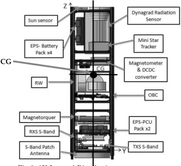
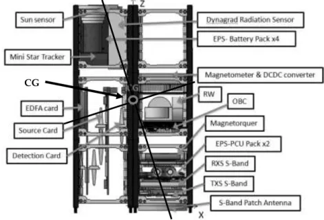
Fig 4. Internal distribution JumpSat 6U-version1
CG
In both versions the mass of the complete nanosatellite is around 3.971 kg, in both the inertia around X axis is exactly the same 0.041kgm2, and around the Y and Z axis change lightly, from 0.048kgm2 (version 1) to 0.052kgm2 (version 2) around Y axis and from 0.014kgm2 (version 1) to 0.018kgm2 (version 2) around Z axis (difference not important related to the order of magnitude for the attitude of the complete nanosatellite 6U). The main difference come from the position of the center of gravity, the reason of this little changes in the inertias.
Fig 5. Internal distribution JumpSat 6U-version2.
In the version 1 the center of gravity is places in the point (28.5, 47.8, 179.4 mm) while in second version the point is (1.65, 47.9, 179.4 mm). As it can be observed on the results the Center of Gravity (CG) in the version 2 is better if do not keep in mind where the subsystems are placed because it is places almost in the geometrical center of the vol-ume. It is completely natural stable and if the AOCS active subsystem is placed through this point it would be ideally perfect to implement any maneuver.
Then it has to be compared both internal distributions, shown in Fig 4 and Fig 5. Always keeping in mind that optical fiber has to be in the outer place as possible in order to do not be heated more than expected by specifications and as well they do not have to be never under 0⁰C, if not it would not work anymore. Then the Source Board is going to heat all time is going to be working so it has to be place closed to the elec-tronics NIMPH board and far from the other subsystems that are going to heat such as batteries, magnetotorques, etc.
Both versions are lightly the same but with some significant differences. Their comparison it can be appreciated in Table 1.
6U-v1 6U-v2
CG shifted to one side CG in the center, more stable CG within the RW CG not within the RW
No interferences with NIMPH Possible interferences with NIMPH Previous subsystems analysis still valid Needed new subsystems analysis Table 1. 6U Comparison
Finally, it appears that the best solution is version 2. The payload’s interfaces with the platform should not be a great issue, it will only take more time solve the way payloads are fixed to the platform. The main problem should be placing the reaction wheels through the center of gravity. In fact, that is not a huge problem due to the distance from Reaction Wheels (RW) to Center of Gravity (CG), which is very small. This location issue is just in terms of fixation and it would be some solve improving NIMPH structure size defined today. Once this size issue will be solved, that way the stabilization of the Nanosatellite and their ma-neuverability would be ideal.
3. Mock-up
In order to have a good idea in reality of all these models and computa-tions in the computer, to have a better idea for people that they do not have a good spatial vision, and with the last aim to show the Nanosat-ellite in futures meetings with all the entities involved in this project it has been decided to create a very useful mock-up using a 3D printer “Leapfrog Creatr HS”.
The structure used for this mock-up is the actual structure already bought from ISIS, and all other components have been printed with the 3D printer and stacked to the empty boards with and adhesive. Finally complete nanosatellite is build up following the ISIS recommendations [3].
Thermal approach for 6U model
Space is a hostile environment for any spacecraft with temperatures ranging from -130⁰C to + 120⁰C with very quick changes and in magni-tude along the time. The aim of a thermal-control subsystem is to main-tain all the elements and equipment belonging with the spacecraft within their temperatures limits for all mission phases [6]. Moreover, analyzing the thermal aspects of a satellite in Low Earth Orbit, it is necessary to consider each mode of heat transfer. These modes within the Nanosatel-lite studies are conduction, and radiation.
1. Important input parameters
In order to have an accurate thermal model some previous definitions are needed. During the Phase 0/A of a mission, concerning the thermal aspect, it is necessary to analyze the specifics thermal needs, the envi-ronmental constraints and check the weak and strong point of the design. Dealing with this task the mass budget, with 20% of margin maximum, and the operating temperatures ranges has been developed according to the datasheet specification of each components for the COTS and with the direct demand to the developer for the customized payloads or sub-systems.
The mass budget has been computed from different sources such as CAD model, datasheets, or information from the researchers and developers involved in those projects. The total mass is 3.98 kg for 6U design and 4.78 kg for the same platform with 20% margin (due to many compo-nents are still under development), the maximum usually taken in large satellites.
One of the main parameters to keep in mind before any thermal analysis is the range of operating temperatures of all the units. This knowledge, in addition to a mathematical model analysis, will lead to the proposal of any kind of suggestions in terms of accommodation or temperatures. Some components would, maybe, require heaters to operate or, maybe another ones will need a cooler.
The most constraining temperatures are the maximal operating temper-ature for the Star Tracker, and the minimum operating tempertemper-ature for solar cells and Nimph. If the internal temperature where the NIMPH is accommodated is lower than 0⁰C (keep in mind it is still under develop-ment and improving all their specifications), it will not work, or idem for the Star Tracker if the temperature is higher than 40⁰C along the mission.
Solar cells are other of the most constraining in terms of low operating temperature, as expected due to there are built up with a diode. This element let solar cells being operative when they are exposed to solar energy and over twenty degrees even if they have been in eclipse and their photovoltaic sensor have not received any light, avoiding any dam-age due to low energy or low temperature.
2. SimuSat
Thermal preliminary analysis simulation have been carried out with the SimuSat suite.
SimuSat is a satellite simulation software. There are available modules for accurate simulation of the energy and attitude control subsystems. It is possible to perform a simplified simulation of the thermal behavior. This software, in constant evolution, associated with Satorb is a powerful simulation tool for a complete space system. [7]
Fig 6. SimuSat Suite Interface [8]
The thermal budget module is based in the thermal nodal model, but it has some limitations: only one node per face and one interior. SimuSat is able to design a satellite with square, hexagon, or circle.
3. Assumptions
The 6U JumpSat is a prismatic body with a rectangular base, it makes 10x20x34cm. Finally the simulation was approach to a squared prismatic nanosatellite, like the 3U JumpSat (10x10x34cm), keeping in mind that the extra payload NIMPH has no volume and it is stacked to the external face (–X).
In order to compute the temperature in the internal body and on the face with solar arrays, as well it has to keep in mind another assumptions for this study:
Conduction factor with the body is equal to 20.
The Printed Circuit Boards (PCBs) where the solar cells are placed are painted in white (α=0.2 & ε =0.9).
Body heat capacity values has been taken as intensive thermal capacity from the electronics boards specifications in [9]. Then it has been divided by the weight of the 6-units JumpSat with mar-gins (around 4.7kg) giving the value such as 188 J/K.
Central body values have been from taken [9]. All internal parts have been simulated as aluminum and electronics; α=0.91 & ε =0.9.
version of the program, there is no option for giving them any thermal property.
For all these studies, the orbital parameters used is detailed in this paper in “Introduction/3. JumpSat+Nimph Mission”. Taking into account those parameters, thermal studies has been performed at:
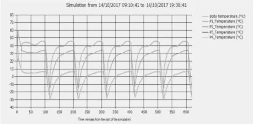
Date : 14/10/2017 Time : 09h10m41s 4. Results
After all those assumptions the temperatures figured out by SimuSat can be appreciated in the Fig 7 during six orbits, in order to let the system stabilizes itself and gives accurate and real results.
First thing to be explained is the notation, P1 is the +X face, P2 is +Y, P3 is –X and P4 is –Y. Moreover the temperatures in faces –X and +/-Y are completely the same.
Regarding the result in Fig 7, it can be assured that the face with the most temperature is the one facing the Sun, as expected, even more than the central body. This preliminary analysis it is shown that the new orbit and the bigger and weightier nanosatellite favors the decrease of temperature, with respect to the 3U study, but it is still a little bit high which is easily to heat than to cool, and support the possibility to not deploying the solar arrays.
Regarding the range of temperatures and the temperatures analysis, it would be important to focus first on the max operating temperature of the different units. The internal temperature, once stabilized, it reaches every orbit peaks over 40⁰C, around 47⁰C, which is higher than the limit by specification for operating of the Star Tracker (40⁰C is their opera-tional temperature limit). Then, it should be cooled in those periods if it is going to be needed, or the payload should be in stand-by mode for this time every orbit. All the other components have no problems with respect to this upper limit on temperatures.
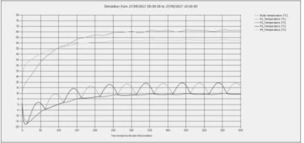
Fig 8. Temperature analysis for 3U model made by my colleagues
Now if the lower limit is observed, the most critical payload is NIMPH with an operational minimum temperature equal to 0⁰C. Keeping in mind that the NIMPH was simulated as stacked in the face –X it has been observed the same effect as the one already explained for the Star Tracker. Then, the solutions could be either being operative during pe-riods of the orbit it is over 0⁰C or either to install a heater close to that face. The other components have no problems with temperatures, no more needs of cooling or heating a unit.
Finally it can be assured that the face with the most temperature is the one facing the Sun, as expected, even more than the central body. Any-ways a depth analysis with more possibilities to create nodes in the areas of interest has to be done. After this preliminary analysis it is shown that the new orbit and the bigger and weightier nanosatellite favors the decrease of temperature with respect to the 3U study made by my pre-vious colleagues and shown in Fig 8. Anyways, even if temperature is still a little bit high, components now support the possibility to not de-ploy the solar arrays and use thermal controllers: either passive or active.
Conclusions and Perspectives
A three-dimension (3D) mock-up of the platform has been produced to demonstrate the design concept with a 3D printer.
Within this new 6-Units CubeSat model, temperatures are lower than they were in the closed model of 3U. Then, it is better for the whole mission, simplifying the architecture and power distribution.
Moreover, this new free unit led to the possibility of embedding a re-entry system, if it is necessary. After some studies from ISAE-SUPAERO students it has been set that there is no necessity of this kind of tech-nology for this configuration of 6U [10].
Then, it can be placed any active thermal control unit, if future analysis says that it will be required. Hypothetical active thermal control unit is feasible in this configuration due to the increment in power budget, thanks to the major number of solar cells. Then, the only limitation it will be because of the number of batteries and their capacity of power transfer.
Due to the lack of big power generators in the current analysis, passive thermal controls are first option for this nanosatellite. Optical coatings are the simplest passive solution which do not add large masses to the satellite design and should be a first option for thermal control. A sec-ondary option will be the Multi-Layer Insulator (MLI). Best thermal control compromise will arrive with the combination of both passive methods.
Optical coatings are layers of paint added to satellites in order to change the optical properties of a surface for increased radiant performance. These coatings are usually highly emissive, and with low solar absorption in order to radiate excess heat and lower the temperature of the satellite surface and systems inside. This technology will be useful for the project because they do not require power consumption.
Multilayer insulation blanket is a material consisting of several insulat-ing barriers. Each barrier has insulatinsulat-ing effects. This MLI mitigate the radiant or conductive heat transfer. It is one of the best solutions to maintain the internal temperature within the limits because it is a low mass and simply thermal control technology, and it has no requirement of power consumption.
Best thermal control solution should be a combination of both MLI and optical coatings. The MLI mainly in faces pointing the Earth, and the white paint in the face pointing the deep space. Then, all the others are covered by solar cells and they will have optical protections. These pro-tections are established thanks to the printed circuits needed for solar
cells assembly.
Another passive thermal control solution would be using just a metallic radiator (aluminum) in order to evacuate the extra flux to space. A “hot box” could be considered between the magnetotorquer and the Energy power Subsystem - Power Distribution Control Unit (EPS -PDCU) with 2 batteries due to its current accommodation.
If it is necessary to consider any other active thermal control: Heaters or thermal switchers are a simplistic active solution for nanosatellites and can be easily integrated when a passive solution cannot be found. Peltier, or TEC (Thermo-Electric Coolers), elements have high power consumption requirements and though may be feasible for larger satel-lites. It is very sensitive and accurate but you need ten times more power than the power to dissipate cooling a component. Then, if there is enough power budget could be a great solution for cooling the required hot com-ponents.
All these studies, analysis, results and definition were available for last nine months. Since this summer, some differences have appeared with respect to the missions and definitions.
Finally for both missions it has been decided to carry them out in two different missions instead of a combined one. First mission that is going to be accomplished is Nimph, using a 3U platform. It is going to be supported by CNES and the platform will be similar to the EyeSat [11] one, where ISAE-SUPAERO students are collaborating on the low cost Star Tracker (similar to the JumpSat’s one).
Once NIMPH mission will achieve their objectives, JumpSat mission will accomplished as defined at the beginning, maybe with the same platform for NIMPH, or their own platform, it has to be defined.
The main point for future work shall come from the need of an accurate thermal analysis based in a depth nodal method, with an appropriate tool.
Acknowledgements
Stéphanie Lizy-Destrez, from the Département Conception et Conduite des véhicules Aéronautiques et Spatiaux (DCAS) at the Institut Supé-rieur de l’Aeéronautique et de l’Espace, provided extremely valuable help and advice concerning the solution to different problems appeared along the project. Mock-up components fabrication was completed, using a 3D printer, by Valentin Guinet student from second year at the Institut Supe´rieur de l’Aéronautique et de l’Espace. This work could not exist without the team’s enthusiastic collaboration and ingenuity.
References
[1] Lucas, William and Rouanne-Labe, Anne and Grave, Julien and Peille, Philippe and Lizy-Destrez, Stéphanie: Jumpsat: Qualifying Three
Equip-ments In One Cubesat Mission, 2013,
[2] J.D.Gayard: Conception d'une charge utile opto-microonde pour picosatel-lite, Thales Alenia Space, 2013,
[3] G.W.Leddink: Tips-n-Tricks, 2012,
[4] G.W.Lebbink: Assembly Manual ISIS 3-Unit CubeSat Structure-v.2.1,
2012, ISIS.STS.3U.TN.015,
[5] ISIS : CubeSat Structures Specifications, 2012, [6] http://www.esa.int/TEC/Thermal_control, [Online],
[7] Lizy-Destrez S., Causse M., Kamali S: Application de la démarche d'ing
é-nierie de système pour la conception d'une plate-forme d'ingénierie
simul-tanée pour les avant projets spatiaux, 2011, Génie Logiciel n° 96, ISSN
1265-1397,
[8] ISAE-SUPAERO website, http://recherche.isae.fr/en/node/2492,
[9] BRIET Richard: Controle Thermique in Tecniques et Technologies des
Véhicles Spatiaux, 2012,
[10] Jérôme Hardouin, Toan NHAM: NIMPH – JUMPSAT, 2014.
[11] Anny Chantal Levasseur-Regourd, Jérémie Lasue, A. Gaboriaud, C. Buil, A. Ressouche, F. Apper, M. Elmaleh: Eye-Sat, a triple Cubesat to monitor
![Fig 6. SimuSat Suite Interface [8]](https://thumb-eu.123doks.com/thumbv2/123doknet/3212824.91866/14.722.216.512.200.425/fig-simusat-suite-interface.webp)