HAL Id: tel-01723758
https://pastel.archives-ouvertes.fr/tel-01723758
Submitted on 5 Mar 2018HAL is a multi-disciplinary open access archive for the deposit and dissemination of sci-entific research documents, whether they are pub-lished or not. The documents may come from teaching and research institutions in France or abroad, or from public or private research centers.
L’archive ouverte pluridisciplinaire HAL, est destinée au dépôt et à la diffusion de documents scientifiques de niveau recherche, publiés ou non, émanant des établissements d’enseignement et de recherche français ou étrangers, des laboratoires publics ou privés.
switch
Wiem Samoud
To cite this version:
Wiem Samoud. Performance analysis of hybrid opto-electronic packet switch. Optics / Photonic. Télécom ParisTech, 2016. English. �NNT : 2016ENST0058�. �tel-01723758�
T
H
È
S
E
EDITE - ED 130Doctorat ParisTech
T H È S E
pour obtenir le grade de docteur délivré par
TELECOM ParisTech
présentée et soutenue publiquement par
Wiem SAMOUD
le 11 Octobre 2016
Analyse de Performance
d’un Commutateur de Paquets Hybride Opto-Electronique
Performance Analysis of Hybrid Opto-Electronic Packet Switch
Directeurs de thèse : Cédric Ware et Mounia LourdianeJury
Mme Catherine LEPERS,Professeure, Télécom SudParis, Évry, France Présidente
Mme Annie GRAVEY,Directrice d’étude, Télécom Bretagne, Brest, France Rapporteure
Mme Christine TREMBLAY,Professeure, École de Technologie Supérieure, Montréal, Canada Rapporteure
M. Nicola CALABRETTA,Maître de conférences, Technische Universiteit Eindhoven, Pays-Bas Examinateur
M. Dominique CHIARONI,Ingénieur de recherche, Nokia Bell Labs, France Invité
Mme Esther LE ROUZIC,Ingénieure de recherche, Orange Labs, Lannion, France Invitée
M. Cédric WARE,Maître de conférences - HDR, Télécom ParisTech, Paris, France Directeur de thèse
Mme Mounia LOURDIANE,Maître de conférences, Télécom SudParis, Évry, France Co-Directrice de thèse
TELECOM ParisTech
école de l’Institut Mines-Télécom - membre de ParisTech
La fibre optique demeure le support de transmission le plus utilisé, portant le trafic à une énergie par bit relativement faible. Cependant, à cause de l’absence de mémoire tout-optique pratique, la commutation de paquets est toujours exécutée électriquement. Les conversions Optiques Électriques Optiques (O-E-O) nécessaires font de la commutation l’un des domaines les plus consommateurs d’énergie. Ce problème est de plus en plus important especialement avec la croissance exponentielle du trafic dans les réseaux optiques. Un défi majeur à prendre en considération dans la conception de futurs réseaux optiques est la restriction de leur consommation énergétique. De ce fait, dans le cadre de cette thèse, nous étudions un commutateur hybride opto-électronique qui consiste en une matrice de commutation optique complétée par une mémoire électronique partagée. L’analyse de performance prenant en compte différentes classes de service, distri-butions de paquets et méthodes de connectivité du commutateur (canaux WDM et/ou SDM), montre que, grâce aux stratégies de commutation établies, le commutateur hy-bride répond aux besoins de toutes les classes de service en termes de taux de perte de paquets, la charge durable du système et la latence. De plus, il réduit significativement les conversions O-E-O par rapport aux commutateurs électriques commercialisés, puisqu’ils n’auront lieu que pour les paquets mis en mémoire d’attente. Nous défendons que le commutateur de paquets hybride opto-électronique satisfait les exigences en qualité de service et pourrait être une solution prometteuse pour réduire la consommation d’énergie des réseaux optiques.
Mots-clefs : commutation de paquets, gestion de contention, composants
opto-électronique, réseaux optiques, consommation énergétique.
Most transmission systems are based on optical fibers, carrying the traffic at a rel-atively low energy per bit. However, due to the lack of mature optical buffers, packet switching is still performed electrically. The required Optical-Electrical-Optical (O-E-O) conversions make the switching one of the areas with the fastest-growing energy con-sumption. A major challenge that must be met in designing future optical networks is curbing their energy consumption. Therefore, within this thesis, we investigate a hybrid optoelectronic switch which consists of an optical switching matrix supplemented with a shared electronic buffer.
Performance analysis taking into account different classes of service, packet classifica-tions and switch connectivity methods (WDM and/or SDM channels), shows that, thanks to the established switching strategies, the hybrid switch satisfies the requirements of all the different classes of service in terms of Packet Loss Rate, sustainable system load and latency. Moreover, it significantly reduces the O-E-O conversions compared to com-mercial off-the-shelf electrical switches, since they occur only for buffered packets. We defend that the hybrid opto-electronic packet switch meets the requirements on quality of service and could be a promising solution to reduce the energy consumption of optical networks.
Key words: packet switching, contention resolution, opto-electronic components,
optical networks, energy consumption.
To my parents
I would like to express my sincere gratitude to my supervisors, Dr. Cédric Ware and Dr. Mounia Lourdiane for their guidance, wise advices and their great skills. The door of Cédric’s office was always open whenever I had questions or need to discuss with him. His passion and enthusiasm for scientific research are contagious and very inspiring. Thanks for having believed in me and giving me the opportunity of an international collaboration within my stay at Columbia University. Mounia assisted me with her knowledge and stimulating regular discussions. I really appreciate her skills of structuring ideas and papers. Her guidance and motivation helped me a lot. Besides their complementary knowledges in the fields of optical components, networks, simulations, performance analysis..., Cédric and Mounia are very kind persons and it was a great pleasure to work with both of them. Thank you for letting my Ph.D. be an enjoyable and productive experience!
I would also like to thank my committee members, Prof. Catherine Lepers for agreeing to chair the jury, Prof. Annie Gravey for the devoted time and the very valuable comments, Prof. Christine Tremblay, who patiently read my thesis, for the brilliant suggestions that served to ameliorate the quality of my redaction, Dr. Nicola Calabretta and our industrial guests Mr. Dominique Chiaroni and Ms. Esther Le Rouzic for the inspiring questions and the relevant comments and suggestions.
My Ph.D. studies were principally financed by the Tunisian Ministry of Higher Edu-cation and Scientific Research. I would like to thank the scholarships’ committee who believed in me and selected my application. I thank the Tunisian consulate and the academic mission of Tunisia in Paris for their assistance.
I address my gratitude to our group “Groupe de Télécommunications Optiques” re-searchers: Prof. Didier Erasme, Prof. Yves Jaouen, Dr. Renaud Gabet, Prof. Philippe Gallion and Dr. Frédéric Grillot for their encouragement and advices on research, sci-entific presentations and teaching. I thank the head of our department, Prof. Bruno Thedrez, the head of the doctoral school, Prof. Alain Sibille and the administrative staff Chantal Cadiat, Yvonne Bansimba, Zouina Sahnoune, Hamidou Kone, Florence Besnard and Marianna Baziz for their availability and help.
I would like to thank Prof. Keren Bergman, head of the Electrical Engineering depart-ment at Columbia University in New York, for the opportunity to work with her group in the Lightwave Research Laboratory. I thank Dr. Payman Samadi for the opportunity to contribute to his project, Dr. Sébastien Rumley for the inspiring discussions, and all the LRL members for their kind welcome.
My gratitude goes also to the supervisors of my internship in Télécom SudParis, Dr. Yann Frignac and Dr. Petros Ramantanis, and to my teachers in Sup’Com Tunis, Dr. Mourad Menif and Prof. Mourad Zghal. They gave me motivation and enthusiasm to go forward in the field of optical communication.
I would also like to acknowledge the support of my colleagues and friends in Telecom ParisTech, Mohamed, Selma, Asma, Elie, Louise, Chetan, Abir, Karim, Mohammad, Hem-ing, Rafael, Kelly, Chadi, Meriem, Taghrid, Sarah, Moamen, Alaa, Marwa, Zahra, Arwa, Wei, Xin, Indayara, Antonio, Carina, Rupesh, Kevin, Buket, Narasimha, Vicky, Huang, Ravi... Thank you for all the fun we have had in the last three years. Special thanks go to my officemate Dr. Ehsan for the friendly working atmosphere and the nice souvenirs of encouraging each others before the deadlines and during writing our theses. Thanks to Achraf, Mehdi and Hussein who have been always there to support me, all the best to you future doctors!
I would thank my friends outside Télécom ParisTech, Khouloud, Alaa, Asma, Marwa, Ahmed, Assia and Amira. Special thanks to Aloes choir members and to all my friends in Attarab association. Sharing my hobby with you was my way to rest and “recharge the batteries”.
Words cannot express how grateful I am to my parents for all of the sacrifices, the love and the education they provided. A special thanks to my brother and all my family who supported me to strive towards my goals. I would like to express my appreciation to Helmi who was always there to support me through the difficult moments. Finally, I would like to honor the memory of my grandparents who raised us with the values of learning and dedicated work, may they rest in peace.
Résumé ii
Abstract iii
Acknowledgments v
Contents vii
List of Figures ix
List of Tables xii
Glossary xiii
General Introduction 1
Commercial Off-The-Shelf Packet Switches: energy consumption issue . . . 1
All-Optical Packet Switches: lack of mature optical buffers. . . 2
Hybrid Opto-Electronic Switch. . . 3
Outline . . . 3
Framework . . . 4
1 Introduction to optical networks 7 1.1 Introduction . . . 7
1.2 Description of optical networks . . . 7
1.3 Evolution of optical networks. . . 11
1.4 Vision on packet switching in optical networks . . . 29
1.5 Conclusion . . . 30
2 Performance analysis of hybrid opto-electronic packet switch connected through interchangeable channels 31 2.1 Introduction . . . 31
2.2 Architecture of our hybrid switch . . . 32
2.3 Switching performance criteria . . . 33
2.4 Simulation conditions and setup . . . 34
2.5 Performance achieved . . . 38
2.6 Conclusion . . . 47
3 Performance analysis of hybrid opto-electronic packet switch supporting
wavelength-specific packets 51
3.1 Introduction . . . 51
3.2 Switch performance when connected through WDM channels . . . 52
3.3 Performance improvements using Space Division Multiplexing (SDM) in addition to WDM. . . 58
3.4 Supporting specific traffic profile . . . 63
3.5 Conclusion . . . 66
4 Minimizing EDFA power excursions through a machine learning approach 69 4.1 Introduction . . . 69
4.2 An overview of EDFAs . . . 70
4.3 EDFA power excursions . . . 71
4.4 Laboratory experiment: collecting data of power excursions . . . 72
4.5 Machine learning approach: minimizing power excursions . . . 74
4.6 Conclusion . . . 78
General conclusions and perspectives 79
A List of publications 83
B Buffer input ports access management 85
C Distribution of the delays 87
D Synthèse en Français 91
0.1 Electrical switch architecture. . . 2
0.2 All-optical switch architecture . . . 2
1.1 Telecommunication network architecture: core, metro and access networks . 9 1.2 Evolution of “capacity x distance” of optical transmission systems, inspired from: “EDFA, principe et application” E. Desurvire, Wiley 2002 . . . 12
1.3 Evolution of the transmission technology in 1stgeneration optical networks . 13 1.4 Layered architecture in optical networks, inspired from[1] . . . 14
1.5 An Optical Add/Drop Multiplexer . . . 15
1.6 A 3-port optical circulator . . . 16
1.7 2× 2 coupler. . . 17
1.8 4× 4 star coupler. . . 17
1.9 3× 3 passive wavelength router . . . 18
1.10 MPLS operating mode, 1.a: Routing protocols exchange reachability to desti-nation networks; 1.b: LDP establishes label mappings to destidesti-nation network; 2: Ingress LER receives packets and adds labels; 3: LSR forwards packets using label swapping; 4: Egress LER removes labels and delivers packets. Adapted from[2] . . . 20
1.11 Evolution of protocols in optical networks . . . 21
1.12 Basic OCS architecture, inspired from[3] . . . 22
1.13 Basic Store-and-Forward asynchronous OPS architecture, inspired from[3] . 23 1.14 Reamplifying, reshaping and retiming functions. . . 24
1.15 OBS architecture, inspired from[3] . . . 25
1.16 SDN based unified control plane architecture. . . 28
2.1 Hybrid switch architecture . . . 32
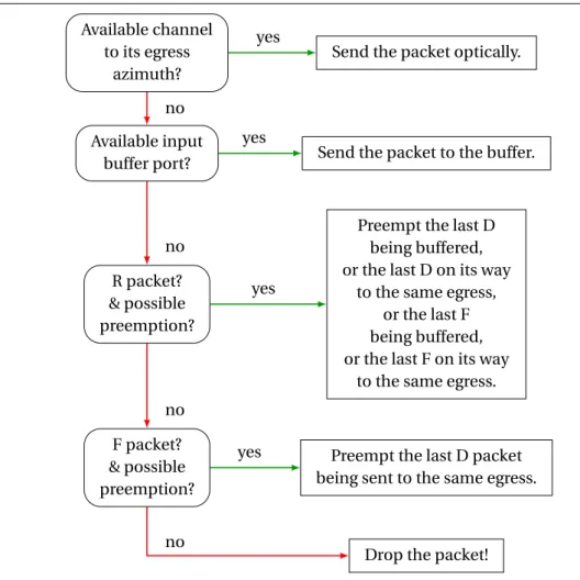
2.2 Classification of services based on different granularity levels, inspired from[4] 35 2.3 Switching strategy, hybrid switch connected via interchangeable channels . . 36
2.4 PLRDvs system load, na = 8, nc= 8 interchangeable channels . . . 39
2.5 PLRFvs system load, na= 8, nc= 8 interchangeable channels . . . 39
2.6 Sustainable system load vs ne/(na× nc) at PLRD= 10−4, na = 8 . . . 40
2.7 Sustainable system load vs ne/(na× nc) at PLRF= 10−4, na= 8 . . . 40
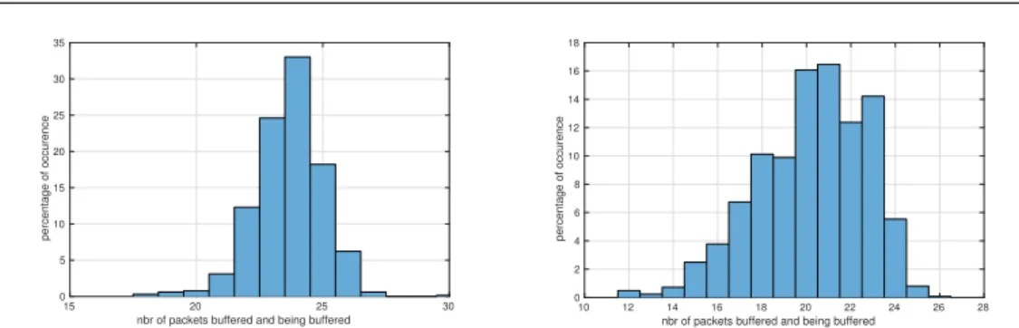
2.8 histogram - occurrence’s percentage of the number of packets buffered and being buffered, na= 8, nc= 8, ne= 12, Left: ρ = 1, Right: ρ = 0.8 . . . 42
2.9 histogram - occurrence’s percentage of the number of packets buffered and being buffered, na= 8, nc= 8, ne= 20, Left: ρ = 1, Right: ρ = 0.8 . . . 42
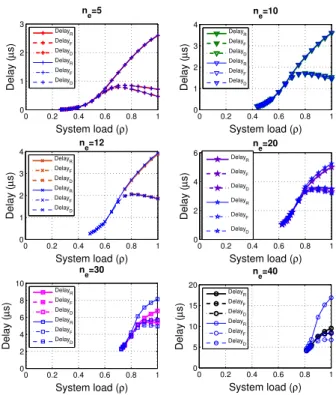
2.10 Delays of R, F and D packets vs system load, (a): na= 8, nc= 8; (b): na= 10,
nc= 10; (c): na= 10, nc= 20 . . . 43
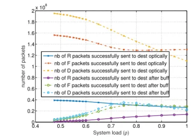
2.11 Nbr of packets successfully sent to their destinations, directly or after
buffer-ization, vs system load, na= 8, nc= 8, ne= 12 . . . 44
2.12 Delay vs system load, Technique of re-emission: re-emission prioritization
(thin curves) vs FIFO (bold curves), na= 8, nc= 8 . . . 45
2.13 Reduction of O-E-O conversions vs system load, na= 8, nc= 8 . . . 46
2.14 Comparison between different packet classes distributions in terms of PLR,
na= 8, nc= 8, ne = 12. . . 48
2.15 Comparison between different packet classes distributions in terms of latency,
na= 8, nc= 8, ne = 12. . . 48
2.16 Comparison between different packet classes distributions in terms of O-E-O
reduction, na= 8, nc= 8, ne= 12 . . . 49
3.1 Sustainable system load at PLRD= 10−4 (Left) and PLRF = 10−4 (Right) vs
ne/(na× nc), na= 8, nc∈ {1, 4, 8, 20, 30} WDM channels . . . 53
3.2 The switching policy in WDM systems . . . 54
3.3 Sustainable system load at PLRD= 10−4 (Left) and PLRF = 10−4 (Right) vs
ne/(na× nc), na= 8 and nc= 8 interchangeable or WDM channels, nw v c v∈
{0, 1, 2, 3} . . . 55
3.4 Delays of R, F and D packets vs system load,(na, nc, ne) = (8,8,30) . . . 56
3.5 Minimum reduction of O-E-O conversions vs ne/(na× nc), na = 8, nc = 4
(Left) or nc= 8 (Right) . . . 57
3.6 Rate of wavelength conversions vs system load, na= 8, nc= 4 (Left) or nc= 8
(Right) . . . 57
3.7 Architecture of (a) SMF, (b) MMF and (c) 7-core fibers. . . 59
3.8 Architecture of hybrid switch connected to SDM-WDM channels . . . 59
3.9 Sustainableρ vs ne/(na× nc× nλ) at PLRF = 10−4, na = 8, nc0 = 8 for
in-terchangeable or WDM-only channels, nc = 4 and nλ= 2 for SDM-WDM
links . . . 60
3.10 Sustainableρ vs ne/(na× nc× nλ) at PLRF= 10−4, na= 4, SDM+WDM links,
nc= 2 (like 2-mode WMMF fibers). . . 61
3.11 Sustainableρ vs ne/(na× nc× nλ) at PLRD= 10−4, na= 8, nc= 1, 2 or 7 (like
7-core fibers) . . . 62
3.12 Sustainableρ vs ne/(na× nc× nλ) at PLRF= 10−4, na= 8, nc= 1, 2 or 7 . . . . 62
3.13 Switching delay vs system loadρ, na = 8, nc= 2 and nλ= 4 for SDM-WDM
channels, n0
c= 8 for interchangeable or only-WDM channels, and ne= 30. . . 63
3.14 O-E-O reduction vsρ,na= 4, nc= 2 SDM channels . . . 64
3.15 λ conversions rate vs ρ, na= 4, nc= 2 SDM channels. . . 64
3.16 Sustainableρ vs ne/(na× nc× nλ) at PLRD= 10−4, na = 8, nc= 7, nλ= 4, for
Cgeneraland Cspecificpacket classifications. . . 65
3.17 Sustainableρ vs ne/(na× nc× nλ) at PLRF= 10−4, na= 8, nc= 7, nλ= 4, for
Cgeneraland Cspecificpacket classifications. . . 65
3.18 Sustainableρ vs ne/(na× nc× nλ) at PLRRnull, na = 8, nc = 7, nλ= 4, for
Cgeneraland Cspecificpacket classifications. . . 66
3.19 Delays vsρ, na = 8, nc = 7, nλ= 4, ne = 100, for Cgeneraland Cspecificpacket
4.1 One-pumping-laser EDFA principle, schematic figure. . . 70
4.2 Schematic figure: AGC amplifier output spectrum, adding a channel with (A)
high or (B) low gain . . . 71
4.3 Setup of the lab experiment, WDM multi-span EDFA network . . . 73
4.4 Screen capture of the OPM software, 24 wavelengths are ON . . . 74
4.5 STD prediction MSE for LR and KBR models, 2-span and 3-span EDFA networks 76
4.6 Comparison between predictions and measurements for single channel add
(left) or drop (right) in 2-span EDFA network . . . 77
4.7 Comparison between predictions and measurements for single channel add
(left) or drop (right) in 3-span EDFA network . . . 77
B.1 Packet Loss Rates of H, M and L classes vs system load (na = 10, nc = 10,
ne = 30) (a): FIFO and Preempt Trans. (b): Sharing and Preempt Trans. (c):
FIFO and Preempt Trans. then Preempt Buff. (d): FIFO and Preempt Buff. then
Preempt Trans. . . 86
C.1 nbr of buffered then switched R packets vs system load, na= 8, nc= 8, ne = 12 88
C.2 nbr of buffered then switched F packets vs system load, na= 8, nc= 8, ne = 12 88
C.3 nbr of buffered then switched D packets vs system load, na= 8, nc= 8, ne = 12 88
C.4 nbr of buffered then switched R packets vs system load, na= 8, nc= 8, ne = 20 88
C.5 nbr of buffered then switched F packets vs system load, na= 8, nc= 8, ne = 20 88
C.6 nbr of buffered then switched D packets vs system load, na= 8, nc= 8, ne = 20 89
D.1 Architecture d’un commutateur électrique. . . 91
D.2 Architecture d’un commutateur tout-optique. . . 92
D.3 Architecture du commutateur hybride opto-électronique. . . 93
D.4 Architecture du commutateur hybride opto-électronique avec des
1.1 Comparison between OCS, OPS and OBS. . . 26
4.1 Training and testing sets sizes . . . 76
ATM Asynchronous Transfer Mode
CAPEX Capital expenditures
CD Chromatic Dispersion
CMA Constant Modulus Algorithm
CoS Class of services
DCF Dispersion Compensation Fiber
DSP Digital Signal Processing
DWDM Dense Wavelength Division Multiplexing
EDFA Erbuim-Doped Fiber Amplifier
FWM Four Wave Mixing
FTTX Fiber To The X
GMPLS Generalized Multi-Protocol Label Switching
GPRS General Packet Radio Service
LED Light-Emitting Diode
LO Local Oscillator
ML Machine Learning
MPLS Multi-Protocol Label Switching
MSE Mean Square Error
MZI Mach-Zehnder Interferometer
OADM Optical Add Drop Multiplexer
OBS Optical Burst Switching
OC Optical Carrier
OCS Optical Circuit Switching
O-E-O Optical-Electrical-Optical
OFDM Orthogonal Frequency Division Multiplexing
OPEX Operational expenditure
OPS Optical Packet Switching
OSNR Optical Signal to Noise Ratio
OTN Optical Transport Network
PDM Polarization Division Multiplexing
PLR Packet Loss Rate
QoS Quality of Service
ROADM Reconfigurable Optical Add Drop Multiplexer
SAP Service Access Point
SDH Synchronous Digital Hierarchy
SDM Spacial Division Multiplexing
SDN Software Defined Network
SONET Synchronous Optical Network
STD Standard Deviation
STS Synchronous Transport Signals
TCP Transmission Control Protocol
TDM Time Division Multiplexing
UMTS Universal Mobile Terrestrial System
VoIP Voice over IP
WDM Wavelength Division Multiplexing
Telecommunication networks have evolved in order to fulfil the growing demand of bandwidth, long transmission distances and good quality of service. Nowadays, optical fibers are the main data carrier for ultra high bit rate transmission, in core, metro and even in access networks. Telecommunication networks based on optical fibers are also called optical networks, even though other technologies (electronics, radio) may be involved too.
Optical networks are far more reliable and faster, consume less energy, and offer greater transmission capacity than conventional copper-wire or radio networks. They experienced up to five generations marked by several evolutions of optical components, technologies and protocols. However, point to point transmissions don’t involve traffic routing across all the network. In fact, current optical networks still include several electronic equipments, especially in the intermediate nodes such as switches and routers. For the past few years, all traffic has been transported as packets, mostly as IP packets. These packets may carry control information, digital data (file transfer), voice (voice over IP), streaming video, on-demand video... Packet switching has its benefits and drawbacks compared to circuit and burst switching. Yet, nodes should ideally exploit packet switching since the packet is the most common form of transporting data. In current optical networks, off-the-shelf packet switches are electrical ones.
Commercial Off-The-Shelf Packet Switches: energy
consumption issue
Although most traffic is carried as optical signals, at a relatively low energy per bit, packet switching cannot currently be performed in the optical domain. All traffic trans-mitted on optical fibers over a great number of channels per fiber, must be demulti-plexed, converted to the electrical domain at switches level, processed separately, and then re-converted to optical signals for further transmission. Reamplifying, reshaping and retiming (3R) functions are done electronically. Consequently, numerous optical-electrical-optical (O-E-O) conversions are required. The schematic architecture of an electrical switch is presented in Figure0.1.
The O-E-O conversions required for packet switching are energetically costly. There-fore, switching remains one of the areas with the fastest-growing power consumption[5].
We note that Internet’s infrastructure consumes approximately 1% of a developed nation’s total electricity consumption[6], besides, networks electricity consumption is growing at
a rate of 10% per year[7].
With the exponential increase of traffic and the need to support new services, the power consumption is becoming one of the largest budget items. Thus, a major challenge
Electronic Switch O E E O O E E O O E E O O E E O Azimuth 1 Azimuthna Azimuth 1 Azimuthna
Figure 0.1: Electrical switch architecture
that must be met in designing future optical networks is curbing their energy consump-tion[8]. A way to address this problem is to study different switching technologies that
may provide economical energy consumption.
All-Optical Packet Switches: lack of mature optical buffers
Some researchers look ahead to "all-optical" networks, where switching is done op-tically from one end-user to another. All-optical packet switches (OPS) would do away with O-E-O conversions and reduce energy consumption. Generally, optics lead to lower energy cost per bit transmitted and some studies arguments that OPS would be a great way to achieve energy efficiency in the fiber-optics realm[9,10]. The architecture of an
all-optical bufferless switch is presented in Figure0.2.
Optical switch Channelnc Channelnc Channel1 Channel1 Channelnc Channelnc Channel1 Channel1 Azimuth 1 Azimuthna Azimuth 1 Azimuthna
Figure 0.2: All-optical switch architecture
Since the years 2000’s, several studies have been done on optical packet label concep-tion[11], recognition and swapping [12,13]. 3R regeneration is possible in the optical
domain[14]. Besides, the clock extraction and synchronisation in all-optical switches has
been evolved[15]. However, all-optical switching solutions have not yet been
the lack of mature optical buffers. In fact, the storage of optical signals remains an almost impossible and expensive operation.
Without practical and mature optical buffers, all-optical packet switches are extremely vulnerable to contention. We remind that contention takes place when two (or more) coincident packets are to be forwarded to the same output port. To resolve the contention, one of the packets must be buffered, or routed to another destination depending on a strategy of deflection routing. For IP traffic, the proper contention solution is buffering. If it is not possible to resolve the contention, at least one of the packets in contention will be dropped.
Because of the difficulty of resolving packet contention, all-optical packet switches lead to notable Packet Loss Rates (PLR) even at unrealistically low loads[16,17,18]. Thus,
they haven’t been deployed operationally yet.
Hybrid Opto-Electronic Switch
Instead of trying to completely replace electrical packets switches by optical ones, a smarter approach could be combining the benefits of the two fields, elctronics and optics. Roles are assigned according to abilities: electronics perform complex processing, while optics transmit packets rapidly and at a lower energy cost.
Therefore, a hybrid optoelectronic switch was proposed[19] and demonstrated [20,
21]. It consists of an optical switching matrix supplemented with a shared electronic
buffer. Packets are switched optically through the switching matrix whenever it is possible, otherwise, in case of contention, they will be stored into the buffer. The hybrid switch doesn’t do away with all O-E-O conversions, but limits them to the cases where contention would have resulted in packet loss.
Compared to all-electrical switches, energy consumption could be reduced since O-E-O conversions will take place only for buffered packets. Moreover, previous performance analyses show that, compared to all-optical switches, the hybrid switch leads to better performance since it could better resolve packet contention thanks to its electronic buffer[22]. The architecture of our hybrid switch will be presented in Figure2.1.
Outline
Our work falls within the context of non-conventional network architectures, able to coexist with existing applications while making the most of optical technologies. Optics would not only be used for information transmission, reduced to the physical layer of conventional networks, but also would be integrated in the higher functionality of packet switching. Moreover, our target is not to avoid completely electronic technologies, that are perfect for data processing and storing, but to use them alongside with, and at the service of optics. Therefore, we aimed in particular to investigate the performance of the hybrid opto-electronic packet switch that could be a potential solution to reduce networks’ energy consumption.
In chapter1of this manuscript, we present an overview of optical networks: their structure, their challenges, and the benefits and drawbacks of optical transmission. We depict the evolution of optical networks and technologies from their first to the fifth
generation. We present also the state of the art in studies related to hybrid optoelectronic packet switches. The next chapters are dedicated to our contributions.
In chapter2, we analyse the performance of the hybrid switch taking into account different classes of service. This implies the establishment of switching, buffer access and buffered-packet re-emission strategies that permit to meet the requirements of each class in terms of the quality of service (QoS). We first assume that our hybrid switch is connected to other nodes through interchangeable Space Division Multiplexed (SDM) channels. We consider as performance criteria the Packet Loss Rate (PLR), the sustainable system load[23,24], and also the switching latency [25,26].
We extend our investigation in chapter3by simulating our switch connected to other nodes via Wavelength Division Multiplexed (WDM) channels. Adding the wavelength constraint, we expect a degradation of switching performance compared to the case of interchangeable channels[27]. Thus, we propose two solutions to offer some
interchange-ability while using the switch in a WDM context. The first solution is supplementing the hybrid switch with shared wavelength converters[28]. We will discuss if the energy
consumption of those converters may negate the energy savings achieved by the hybrid switch compared to electrical switches. The second solution is combining SDM and WDM at the level of the connected optical ports: connecting the switch to SDM (multimode or multicore) fibers supporting WDM on each mode or core[29,30]. We will show that
high sustainable system load, low switching latency and a significant reduction of O-E-O conversions are achieved.
The quality of service could be associated with the quality of transmission, for instance, a higher-priority packet should be switched via a higher-power channel. We remind that adding (or dropping) a channel to (or from) a WDM system based on multi-span EDFA transmission may lead to power excursions. So, a potential wavelength conversion of a packet should take into consideration its class of service, the existing wavelengths in the system, and the classes of service of other switched packets at that time. Therefore, we propose in chapter4a Machine Learning (ML) approach that could give the best recommendation of which wavelength to add (or drop) to (or from) a WDM system with minimal power excursions. Laboratory experimental work is done to train and test our ML approach. The application of our ML approach is not reduced to the choice of a wavelength to which a packet should be converted in order to minimise power excursions and achieve best switching performance considering the different classes of service, but it is applicable to different architectures of WDM multi-span EDFA networks[31,32].
Finally, we summarize the lessons learned in this manuscript and conclude on the benefits of the hybrid optoelectronic switch that could be a promising solution to curb networks energy consumption. Further studies are recommended as perspectives of this work.
Framework
Within the Ph.D. program of doctoral school "École Doctorale en Informatique, Télé-communication et Électronique (EDITE)" of Paris, research works are done in Télécom ParisTech, Université Paris-Saclay under the supervision of Dr. Cédric Ware, associate
professor-HDR in Télécom ParisTech and Dr. Mounia Lourdiane, associate professor in Télécom SudParis.
Part of this work (chapter4) was achieved during my 4-month stay in the Ligthwave Research Laboratory of Columbia University in New York, within the initiation of an exchange program between our institution Télécom ParisTech, Université Paris-Saclay and Columbia University.
This thesis is mainly financed by a 3-year scholarship grant provided by the Tunisian Ministry of Higher Education and Scientific Research based on academic excellence criteria.
The work presented in this manuscript has led to publications presented in ap-pendixA.
Introduction to optical networks
1.1
Introduction
The incorporation of optical fiber in telecommunication networks has significantly im-proved their performance and impacted our society: high data rates, long intercontinental reaches, low latency, reliable networks are achieved.
In fact, the exponential traffic growth in “big data” generation and cloud-based ser-vices couldn’t be managed without the use of optical components and technologies. Besides, studies on optical communications must continue to address the key require-ments of future networks, which are the increasing demand on high data rate transmission and the reduction of their cost and energy consumption.
In section1.2, we begin with a description of telecommunication networks: compo-sition, challenges and classifications. Then, we focus specifically on optical networks. We depict the advantages and the limitations of optical transmission, on which optical networks are based.
Since their use in 1980’s, optical networks have known important and steady evolution, experienced several generations which we present in section1.3. A particular attention is given to the 4th generation marked by optical switching.
In section1.4, we present our vision on packet switching in optical networks: in-stead of commercial off-the-shelf electrical switches that are energetically costly, and all-optical switches that are not practical and vulnerable to contention, hybrid opto-electronic switches could be a good compromise and a key solution to reduce the energy consumption with a proper management of packet contentions.
1.2
Description of optical networks
An optical network is a high-capacity telecommunication network in which informa-tion is transmitted mostly through optical fibers. We begin with generalities on telecom-munication networks.
1.2.1 Telecommunication networks
A telecommunication network is a collection of nodes and links to enable communi-cation at a distance according to protocols. This definition seems to be obvious thanks to the impact of telecommunication networks in our daily lives. For examples, the
phone network, the radio broadcasting system, computer networks and the Internet are all telecommunication networks. The nodes in the network are the devices used to enable the information transmission and processing, such as repeaters, routers or data centers. The links are the transmission medium which carry the information from a device (emit-ter) to another (receiver). They may be wired links, such as wisted pairs, coxial cabels and optical fibers, or wireless links through electromagnetic waves.
1.2.1.1 Telecommunication networks challenges
The "classical" challenge in designing telecommunication networks is to provide a big transmission capacity, i.e. an important transmission rate, through long distances. Telecommunication networks have been remarkably developed to provide several services (e-mail, e-administration, e-commerce, e-health, e-education...) at a good quality and with high transmission capacity. For instance, Alcatel-Lucent launched in 2015 a 1-port 400 Gb/s Internet Protocol (IP) line card for IP networks that connects routers at speeds of 400 Gb/s line rate over hundreds of kilometers [33]. However, since the amount of data
circulating on networks is exponentially increasing, responding to the need of networks customers in terms of transmission capacity is and will always be a challenge.
A second important challenge is to reduce and achieve reasonable cost, which is composed by:
– Capital expenditures (CAPEX) that are calculated based on equipement costs such as : network links, intermediate nodes... The reference[34] presents the CAPEX’s
evolution of different competitive telecommunication operators. For example, the CAPEX of the telecommunication operator Zayo has risen by 10%s from 2013 to 2015.
– Operational expenditures (OPEX) that include the costs generated during network lifetime such as energy consumption, network supervision ans maintenance. The audit firm EY presents the evolution of these expenditures in European telecommuni-cations operators and the keys to optimize them[35]. Recent studies are done on flexible
networks that assume the use of tunable transponders (also called bandwidth variable transponders BVT) and a flexible spectrum grid[36]. These elastic networks may reduce
both capital and operational expenditures[37].
Energy consumption has been increasingly an issue of telecommunication networks. It is growing at a rate of 10% per year[7]. Its reduction is a relatively new, but important
challenge. For instance, Internet’s infrastructure consumes approximately 1% of a devel-oped nation’s total electricity consumption[6]. The network energy consumption includes
the power supply of nodes and command systems, but switching function is the most energy consuming field[5]. Considering optical networks, the Optical-Electrical-Optical
conversions at the level of switches and routers are energetically costly[8].
1.2.1.2 Telecommunication networks structure
Three main categories of telecommunication networks can be distinguished from the point of view of their geographical scope: access, metro and core network. This general classification is depicted in Figure1.1.
Access network is the part of a telecommunication network, which connects the
subscribers to the network operator (or service provider) over a distance of a few (≤ 10) kilometers. Based on the operator point of view, the access network is also called the
end user end user institution office central office Core network Metro network Access network
Figure 1.1: Telecommunication network architecture: core, metro and access networks
last-mile network. Different kinds of links have been proposed to access networks, namely copper wires, such as twisted pair and xDSL technologies, wireless links, such as WiFi and WiMax, and optical fibers. Among them, optical technologies are emerging as promising solutions for last mile access, because of the potential of optical transmission (low loss, large bandwidth, noise isolation...)[38,39]. Fiber access networks are also referred to as
Fiber-To-The-x (FTTx) system, where "x" can be "home", "building", "curb"... depending on how deep in the field fiber is deployed or how close it is to the end user. In a fiber-to-the-home (FTTH) system, fiber is connected all the way from the service provider to household users. Local routers transport the traffic from the access network to the metro network. The local routers are also called access routers. Their capacity is relatively low. For example, Cisco 3850 local switch permits to connect up to 48 Ethernet ports with a rate of 1 Gb/s per subscriber and up to 40 Gb/s of wireless capacity [40].
Metro (metropolitan) or regional network covers typically large metropolitan areas
(up to 200 km[41]). It is also called distribution or aggregation network since it is the
intermediate network between core (metro-core) and access networks (metro-access). In general, metro networks are publicly owned, allowing all telecommunication operators open access to the networks.
Metro networks were based largely on Synchronous Optical Networking (SONET) and Synchronous Digital Hierarchy (SDH)[42] which are usually constructed as a series of
protected rings that allow fast fail-over to the alternate "rotation" if a fiber is cut. Rings are connected via optical add/drop multiplexers (OADMs). Nowadays, metro networks are based on wavelength division multiplexing (WDM) systems which increase greatly the transmission capacity.
Information of different types (voice, digital data, video...) is transmitted as IP packets. The balance is being changed between electrical and optical components in metro networks for transmission function. It is almost entirely carried on optical fibers and other electrical functionalities are progressively being replaced by optical technologies (amplification, coherent detection, bypass, circuit switching...). Several research and industrial works are done in this context[43]. However, optics do not yet perform high functionalities such as
packet switching and routing, that are still assured with electronics. Optical-Electrical-Optical conversions are thus required.
The routers of the metro network have to add and drop traffic to and from the metro network, solve the potential issue of link failures, serve as a pass-through hub for core network traffic, manage different services... The routers used in metro-core part have higher capacity than those of metro-access part, in the order of 100 Gb/s and higher for metro-core routers debit, compared to 10 to 40 Gb/s for metro-access routers [44,45,46].
Core networks, also called backbone or long-haul networks, are used between long
distance nodes such as continents. The core network is the central part of a telecom-munication network. It provides interconnectivity of metro and access networks, high capacity and reliable backbone infrastructure. Information from metro networks is ag-gregated[47]. The core network may also provide the gateway to other networks. The
transmission in core network is generally based on optical fibers using WDM, in which case, the telecommunication network may be called as an optical network.
1.2.2 Advantages and Limitations of optical transmission
An optical (photonic, or light-wave) network is a high-capacity telecommunication network in which information is transmitted as optical signals, through optical fibers. We note that the first ITU-T handbook related to optical fibers was published in 1984. Its title is "Optical Fibres for Telecommunications". Since optical fibers are the unrivaled carriers of data traffic over the world in core, metro and access networks, most telecommunication networks are considered as optical ones.
Optical network is based on optical technologies and components, but it does not necessarily imply a "purely optical network", it includes also electronic devices namely electronic switches and routers.
1.2.2.1 Advantages
A few of the most important reasons for migrating to optical networks (rather than electrical and wireless ones) are:
– Large optical bandwidth permits high data rate transmission, which also supports the aggregation of voice, video, and data. In addition, with the use of WDM, Po-larization Division Multiplexing (PDM) and/or in the near futur Space Division Multiplexing (SDM), many signals could be sent simultaneously on one fiber, the capacity of transmission is thus higher.
– Optical fiber has low attenuation, the signal power goes down by only 0.2 dB/km or lower. This means that the transmission distance (reach) may be extended and that the number of optical amplifiers needed is relatively small (1 amplifier per 80 km in transmission systems).
– Immunity to electromagnetic interference (EMI), radio-frequency interference (RFI), crosstalk, impedance problems... This immunity reduces the bit error rate (BER) and eliminates the need for shielding within or outside a building.
– Light as a transmission medium provides the ability for the use of optical fiber in
dangerous environments. Fiber is less susceptible to temperature fluctuations and
fires than copper and can be submerged in water.
– Optical fiber is difficult to tap since it doesn’t radiate signals, thus it provides a higher degree of security than possible with copper wire.
– Light weight and small diameter of fiber permit high capacity through existing conduits.
– Optical fibers are relatively cheap compared to copper lines.
We note that in case of a fiber cut or physical security attack, it is possible to determine the place of damage with precision thanks to the reflectometry.
1.2.2.2 Limitations
Optical networks have also some drawbacks, such as:
– The optical fiber installation cost is quite high, much more important than the cost of the fiber itself. According to[48], civil works cost is the major share of FTTx
deployment, while the fiber cost is only 6%. Moreover, expensive precision splicing and measurement equipment are required. The U.S. Department of Transportation, Research and Innovative Technology Administration (RITA) offers fiber optic cable installation costs for various projects[49].
– Copper cables can carry data as well as power, a last-mile switch or a terminal (for instance a phone) needs just to be branched to the network extremity, the power comes from the distribution central. This is not the case of optical fiber cables which carry only data. An Optical Network Terminal (ONT) must be connected to the optical fiber which carries the data, but also to the power source or outlet. – Although most wired traffic is transmitted through optical fibers, especially in
core and metro networks, packet switching and routing are still performed with electronics, except for quasi-static routing. Thus, packets must be converted to the electronic field at the level of the switch or router and then reconverted to the optical field for further transmission. These required Optical-Electrical-Optical
(O-E-O) conversions are energetically costly. Despite several researches on
all-optical switches that could do away with O-E-O conversions, all-all-optical buffering
solutions (such as Fiber Delay Lines FDL) are still not practical or not mature enough to store packets. Without them, all-optical switches are vulnerable to contention and lead to high Packet Loss Rates (PLR)[16,18]. My thesis deals with
this context (see section1.4). We investigated a hybrid switch that consists of an optical switching matrix supplemented with a shared electronic buffer that collects packets in case of contention. The goal of using this hybrid switch is to reduce the O-E-O conversions (just to the number of buffered packets) compared to electronic switches, while maintaining acceptable switching quality, namely acceptable PLR thanks to the possibility of contention resolution.
1.3
Evolution of optical networks
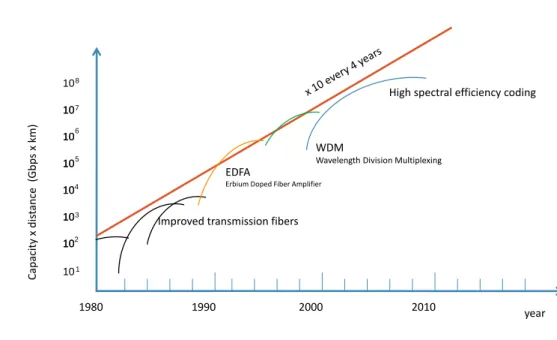
Figure1.2presents the evolution over the years of the product of transmission capacity (Gb/s) and distance (km). It outlines also the major technologies that permitted the evolution of optical networks from a generation to another. An important step in the evolution of optical systems is the development of Erbium Doped Fiber Amplifier (EDFA) in the 90’s which permits to achieve higher propagation distances [50]. Wavelength
Division Multiplexing (WDM), invented in 1992, offers a multiplication of the transmission system capacity since it permits to carry multiple communication channels over one physical optical fiber with each channel operating on a different wavelength. It is noted that EDFA amplifiers may amplify several wavelengths simultaneously. Over the last
decade, optical fiber communication systems have been intensively used thanks to the advancement in the field of digital signal processing, which permits to use coherent detection and advanced modulation formats.
101 10 10 10 10 106 107 102 103 104 105 10 10 108 1980 1990 2000 2010 year Cap aci ty x dis tance ( Gb p s x km) EDFA
Erbium Doped Fiber Amplifier WDM
Wavelength Division Multiplexing
Improved transmission fibers
High spectral efficiency coding
Figure 1.2: Evolution of “capacity x distance” of optical transmission systems, inspired from:
“EDFA, principe et application” E. Desurvire, Wiley 2002
This evolution in the optical transmission implementations has reinforced the use of optics in telecommunication networks[51]. Besides, the use of optics has exceeded
the transmission functionality. Until now, optical networks have reached 5 generations presented as follow:
1.3.1 First-generation optical networks: Point to Point transmission
First-generation optical networks were composed of optical fiber point-to-point (P2P) transmission links, substituting copper-based lines maintaining the terminating elec-tronic equipment.
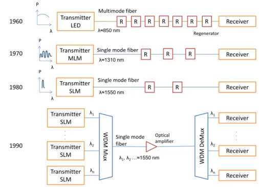
The emission was first assumed by Light Emitting Diode (LED), then Multi-Longitudinal Mode (MLM) lasers and then Single-Longitudinal Mode (SLM) lasers[52]. Compared to
LED, an MLM laser permits to send light with higher power, reach longer distances (up to 10 km[53]) and thus reduce the number of required regenerators. MLM, also referred to
as a Fabry Perot laser diode (FP), can be used forλ = 1310 nm but not for λ = 1550 nm due to the higher chromatic dispersion of this window. Forλ = 1550 nm, SLM lasers are used since they have an additional frequency selective item[52]. SLM emission may reach
up to 20 km[53].
Figure1.3presents the evolution of signal P2P transmission in the 1stgeneration
optical networks. Since 1990’s, WDM systems are widely used. Different signals (channels) are generated at different wavelengths, combined and coupled into an optical fiber using WDM multiplexer. Optical amplifiers can be used in the transmission chain. At the
P λ Transmitter LED Transmitter SLM Transmitter MLM Transmitter SLM Transmitter SLM Transmitter SLM . . . Receiver Receiver Receiver Receiver Receiver Receiver Multimode fiber
Single mode fiber
W DM Mux W DM DeMux R R R R R R R R R R R R λ≈850 nm λ≈1310 nm λ≈1550 nm λ1, λ2 …≈1550 nm λ1 λ2 λn λ1 λ2 λn Regenerator Optical amplifier P λ P λ 1960 1970 1980 1990
Single mode fiber
Single mode fiber
. . .
Figure 1.3: Evolution of the transmission technology in 1stgeneration optical networks
reception side, a demultiplexer separates the different channels. Each one is collected by its wavelength-specific receiver. Dense wavelength division multiplexing (DWDM), employed since mid 90’s, uses the same transmission window but with denser channel spacing. By 2000 and so, DWDM systems use L-band (centered at 1625 nm) besides to C-band (centered at 1550 nm). Channel plans vary[54], but a typical nowadays system
would use 40 channels at 100 GHz spacing or 80 channels with 50 GHz spacing or more than 160 channels at 12.5 GHz spacing.
First generation optical networks were based on the protocols Synchronous Optical NETworking (SONET, in USA) and Synchronous Digital Hierarchy (SDH, in Europe and Japan). SONET defines Optical Carrier (OC) levels and electronically equivalent Syn-chronous Transport Signals (STS). The standard STS-192, OC-192 operates at 10 Gb/s, while the standard STS-768, OC-768 operates at 40 Gb/s. Circuit switching, traffic separa-tion, routing functions are handled with electronics. Thus, optical to electrical (O-E) and electrical to optical (E-O) converters are required.
Respecting the principle of encapsulation in the OSI layered model, IP packets were sent over Asynchronous Transfer Mode (ATM) over SONET. The ATM protocol (layer 2 of OSI model) was designed to unify telecommunication and computer networks. It was responsible for traffic engineering and quality of service, handling non-tolerant packet loss, such as file transfers, and low-latency packets such as voice and (less restrictive) video packets. ATM uses a connection-oriented model in which a virtual circuit must be established between two terminals before the actual data exchange begins.
Optical networks evolved, IP dominated ATM and became sent over SONET in the form of Point to Point Protocol (PPP)[55]. This technique, called Packet over SONET
(POS), combines the simplicity of IP and the high reliability of SONET/SDH. It is used in the connection between gigabytes routers, in the core network.
However, point to point transmissions don’t involve traffic routing across all the network. The first generation suffers from a bottlenecks of excessive electronic proceesing at each intermediate node. Thus, additional functions must be held in the optical domain.
1.3.2 Second-generation optical networks: optical layer
Unlike 1stgeneration networks, second-generation optical networks were intended to
perform additional functions of point to point transmission in the optical domain. Several switching and routing functions are handled optically, but with electronic controls.
The emergence of second generation networks considers the introduction of a new level in a layered network model which is the optical layer. Figure1.4presents the layered architecture in 2nd generation optical networks. The optical (physical) layer contains
optical components executing linear operations on optical signal and provides basic communication services to a number of independent Logical Networks (LNs). LNs are residing in the electronic (logical) layer which contains electronic components executing nonlinear operations on electrical signal.
The optical layer means:
– A reduction of "bottlenecks": In the first generation of networks, the increase of the line speed complicates the header processing in the electronic domain.
– It is a service layer that provides "lightpaths" to its users (other client layers: SDH, ATM, Ethernet ...) through Service Access Points (SAP).
Lecture 5: Introduction to Optical Networks 21/
Optical Communication Systems and Networks
Layered architecture in
telecommunications networks
Future formats Internet Voice ATM Future Services Multimedia SDH/ SONET Existing formats IP Data Customer applications Optical layer WDM transmission Optical cross-connets Electronic layer Access network Access service points 27Figure 1.4: Layered architecture in optical networks, inspired from[1]
A lightpath is an end-to-end optical connection, which takes place in the optical layer by using a specific wavelength along several optical links and through different intermediate nodes. There is a wavelength continuity constraint. Different lightpaths can use the same wavelength unless they do not share the same optical fiber link. Lightpaths are multiplexed and demultiplexed in the optical layer.
The key devices that have marked the 2ndgeneration are:
– Optical Add-Drop Multiplexer (OADM): it takes a WDM signal from its input port and selectively drops some wavelengths locally while letting others pass through,
and also selectively adds wavelengths to the WDM signal, as presented in Figure1.5. It may incorporate wavelength conversion capabilities.
All the lightpaths that directly pass an OADM are termed cut-through lightpaths, while those that are added or dropped at the OADM node are termed added/dropped lightpaths[56]. λ1 λ2 λ3 λ4 OADM λ1 λ2 λ3 λ5 λ4 dropped addedλ5
Figure 1.5: An Optical Add/Drop Multiplexer
– Reconfigurable Optical Add-Drop Multiplexer (ROADM): it is an OADM that al-lows the service providers to define and to re-configure remotely the wavelengths while adding the flexibility which characterizes the network infrastructure mode any-wavelength-to-anywhere (directionless) using any available port on the net-work node (colorless)[57]. ROADMs allow the optimisation of the operating costs
and the reduction of the travels to update and assure the maintenance of the net-works, namely the metro and long haul networks where they are used. Since their invention, ROADM have seen several developments and improvements[58,59]
– Optical circulator: it is a 3 (or 4)-port device that separates optical signals that travel in opposite directions in an optical fiber[60]. An operation diagram of a
3-port optical circulator is presented in Figure1.6.
It may be used to achieve bi-directional transmission over a single fiber: a circulator is located at both ends of the fiber. Each circulator functions to add a signal in one direction while removing the signal in the other.
Because of its high isolation, reflected optical powers and its low insertion loss, optical circulators are widely used in advanced communication systems, add-drop multiplexers, bi-directional pumps, and chromatic dispersion compensation de-vices.
– Ultrawide-band EDFA: The 2ndgeneration experienced some improvements in
EDFA amplification such as proposing different architectures of amplifiers[61]
or using EDFA amplifiers in a building block[51]. This permits to optimize the
dispersion compensation, ensure larger bandwidth and cover more channels in WDM and DWDM systems.
– Optical Cross-Connet (OXC): called also Photonic Cross-Connect (PXC), intercon-nects high-speed optical signals between multiple input fibers and multiple output fibers. It was first used in circuit-switching systems. It may be wavelength-specific (switches the optical signal on incoming wavelengthλi of an input fiber to the
Port 1 Port 2 Port 3 λ Circulator λ1 λ3 λ2 λ3 λ1 λ2
Figure 1.6: A 3-port optical circulator
outgoing wavelength λi of another output fiber) or equipped with wavelength
converters (switches the optical signal of the incoming wavelengthλi of an input
fiber to another outgoing wavelengthλj of another output fiber). In addition to
wavelength switching, OXCs are involved in wavelength routing with the use of multiplexers and demultiplexers. An OXC supports network reconfiguration and permits to restore broken optical paths in optical networks[62]. It may also
in-clude additional optical functions such as chromatic dispersion compensation and Polarization Mode Dispersion (PMD) compensation. Various OXC architectures are explored in[63]. An OXC should provide low switching time, low insertion loss
(which is the power lost caused by the OXC), low crosstalk (which is the power ratio of the power at an output from an input to the power from all other inputs), and low polarization-dependent loss. For instance, the OXC-TM-400 of Enablence has an insertion loss of 3 dB, a crosstalk of 45 dB and a switching response of 3 ms[64].
The notion of Optical Transport Network (OTN) has been defined since the 2nd
-generation optical networks. Its ITU recommendation is G.709. OTN provides a network-wide framework that adds SONET/SDH-like features to WDM equipment. It creates a transparent, hierarchical network designed for use on both WDM and Time Division Mul-tiplexing (TDM) devices. Two switching layers are formed: TDM and Wavelength Switched Optical Network (WSON). Functions of transport, multiplexing, routing, management, supervision, and survivability are defined.
The evolution of optical networks in the second-generation was noteworthy but, higher transmission rates and lower latencies were required. Thus all-optical intercon-nection devices (third generation), that may reduce the electrical control and the opto-electrical conversions, are required.
With the use of reconfigurable devices, such as ROADM and OXC, the concept of Automatically Switched Optical Network (ASON) has been introduced. ASON was based on Multi-Protocol Label Switching (MPLS), then, Generalized Multi-Protocol Label Switch-ing (GMPLS). Both ASON and GMPLS support the second-generation optical networks by defining the optical control plane separately from the data plane in order to set up and release lightpaths[65]. However, these concept/protocol have been evoluted
co-inciding with the development of all-optical interconnection devices that marked the third-generation optical networks. We would rather present them in the next section.
1.3.3 Third-generation optical networks: all-optical interconnection devices
In order to have a network of multi-wavelength fiber links, appropriate fiber intercon-nection devices are needed[51]. These devices may be classified on three categories:
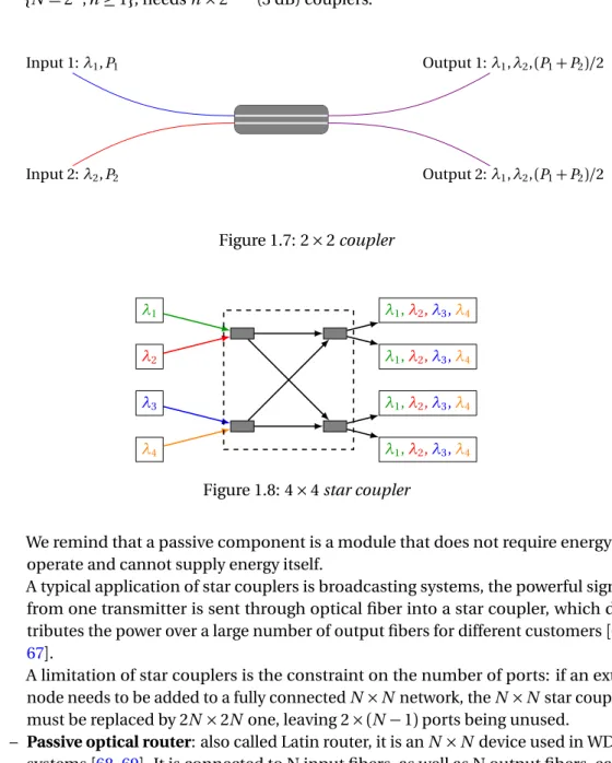
– Star coupler: it is a passive broadcast device that takes in input signals and splits each of them into all of the output signals. It is formed by cascading 2× 2 couplers (named also 3 dB couplers, or splitters); thus, the number of ports is usually a power of 2. An input signal will have its power equally divided among all output ports of the star coupler.
Figure1.7presents one 3 dB coupler, while Figure1.8presents the architecture of 4× 4 star coupler. It is composed by 4 (3 dB) couplers. An N × N star coupler, where {N = 2n; n≥ 1}, needs n × 2n−1(3 dB) couplers. Input 2:λ2, P2 Input 1:λ1, P1 Output 2:λ1,λ2,(P1+ P2)/2 Output 1:λ1,λ2,(P1+ P2)/2 Figure 1.7: 2× 2 coupler λ1 λ2 λ3 λ4 λ1,λ2,λ3,λ4 λ1,λ2,λ3,λ4 λ1,λ2,λ3,λ4 λ1,λ2,λ3,λ4
Figure 1.8: 4× 4 star coupler
We remind that a passive component is a module that does not require energy to operate and cannot supply energy itself.
A typical application of star couplers is broadcasting systems, the powerful signal from one transmitter is sent through optical fiber into a star coupler, which dis-tributes the power over a large number of output fibers for different customers[66,
67].
A limitation of star couplers is the constraint on the number of ports: if an extra node needs to be added to a fully connected N× N network, the N × N star coupler must be replaced by 2N× 2N one, leaving 2 × (N − 1) ports being unused.
– Passive optical router: also called Latin router, it is an N× N device used in WDM systems[68,69]. It is connected to N input fibers, as well as N output fibers, each
one supporting up to N wavelengths, permitting thus to route up to N2signals
optical paths between the inputs and the outputs. Figure1.9shows the architecture of a 3× 3 passive wavelength router.
Input 1 Input 2 Input 3 Output 1 Output 2 Output 3
Figure 1.9: 3× 3 passive wavelength router
Latin routers are called passive since they don’t need to be supplied with power. They have a stable (static) routing table: when receiving a signal, depending on its input port and its wavelength, the output fiber and the optical path is determined. The signal wavelength doesn’t change in the router.
The wavelength on which an input port gets routed to an output port depends on the internal connections between the demultiplexers and the multiplexers inside the passive optical router. These internal connections define the static routing matrix. Usually, for an N× N Latin router supporting N wavelengths, the wavelength λk
carrying signals from the input fiber i to the outport fiber j is determined as[68]:
k=
¨
i+ j − 1 si i+ j ≤ N + 1
i+ j − N − 1 si i + j ≥ N + 2 (1.1)
– Wavelength Selective Cross-Connect (WSXC)[70]: also called as Wavelength
Rout-ing Switch (WRS) or active switch. In fact, it is active since its switchRout-ing matrix can be reconfigured on demand under electronic control. So, the WSXC offers more freedom in rearrangement. Unlike passive star coupler and passive router, the WSXC needs to be supplied with power.
The architecture of a WSXC may be based on micro-mirrors, or OADM, or fiber Brag grattings... The article[71] describes different architectures of WSXCs and makes
comparison between them.
With the use of these devices, O-E-O conversions are not required at each node in the WDM optical system, thereby 3rd-generation optical networks were aimed to reduce costs at each node. Such type of network is called “transparent” network because signals undergo O-E-O conversions only at their respective source and destination, unlike “opaque” network where a signal undergoes O-E-O conversion at every intermediary node
from its source until its destination.
Transparent networks avoid intermediary opto-electronic components and lead thus to a reduction of cost, energy consumption and transmission latency. Nodes would be-come obvious to signal specifications such as the modulation formats, the bandwidth, the channel spacing... However, transparent networks have some limits: the wavelength continuity constraint and the limited transmission distances due to the accumulation of signal loss and deformations [72,73]. Some possibilities to overcome these limits
are[74,75]: increasing the number of transponders per connection, adding more complex
post-processing to compensate for the filtering impact, implementing super-channels, using advanced Forward Error Correction (FEC) codes... These solutions increase the
cost or the implementation complexity of the network. A key solution could be “translu-cent” networks that are a compromise between opaque and transparent networks. In translucent networks, regenerators can be used but their number is limited, and they must be carefully placed at strategic locations. The wavelength continuity constraint can be managed; there is no limitations on the transmission distance; and O-E-O conversions are reduced compared to opaque networks but not totally avoided as in transparent networks[76].
The ASON has been more developed within the 3rd-generation optical networks. An ASON (ITU G.807) is an "intelligent" optical network that can automatically manage the signalling and routing through the network. Configuring cross-connections in the network elements is automated: these elements have the necessary processing functions built in to configure a new traffic path, given a customer requirement of the path’s start and end point, the bandwidth, the Quality of Service... (but not the path itself ). This traffic path will be changed if the network is changed.
ASON is based on the protocol GMPLS. However, other protocols preceded the GMPLS, which are MPLS and MPλS. The hierarchical classification previously used in IP over
ATM over SONET, or in IP over SONET, leads to significant latencies of connections and communications between the different layers. Some management tasks (security, error correcting codes...) and transport protocols were duplicated. MPLS, and following it MPλS and GMPLS, are the alternatives to simplify the network control and management
and overcome the scalability issues.
Multi-Protocol Label Switching (MPLS) was developed in the late 1990s and
stan-dardized by the Internet Engineering Task Force (IETF) in order to provide faster packet forwarding for IP routers.
Traditionally, IP routing is connectionless (and not circuit-switched). At the reception of the packet, a router determines the next hop using the destination IP address on the packet alongside information from its own routing table. Routing tables contain information on the network topology configured statically and synchronized with the network modifications, or obtained via an IP routing protocol, such as Open Shortest Path First (OSPF), Intermediate system to intermediate system (IS-IS), Routing Information Protocol (RIP)... In an ASON network, Internet protocols cannot be used directly. IP routers route packets based on the information extracted from their headers, while OXCs switch on the basis of wavelengths or optical paths.
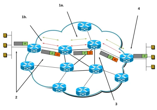
MPLS adds labels that fill in the IP packet header. Thus, it eliminates the IP header interrogating on each packet at every intermediate router, which is a waste of resources especially for packets sent from the same source to the same destination. As presented in Figure1.10, MPLS works as following:
– Ingress Label Edge Router (LER) pushes a label in front of the IP header.
– Label Switch Router (LSR) does label swapping. Inside the network, each LSR uses lables to determine the Label Switched Path (LSP) and forward the packet to the next hop, until the egress router.
– Egress LER removes the label.
Besides the forwarding function, MPLS assumes control function. It permits the routing tables establishing by forwarding tables and network topology information for path selection (OSPF, IS-IS, RIP...). It supports also signaling and Label Distribution Protocols (LDP) by setting up the LSPs. Control and data planes are separated: path is set up using control plane, while data is forwarded via the data plane.
1a. 1b. 2 IP 3 4 IP
Figure 1.10: MPLS operating mode, 1.a: Routing protocols exchange reachability to
destina-tion networks; 1.b: LDP establishes label mappings to destinadestina-tion network; 2: Ingress LER receives packets and adds labels; 3: LSR forwards packets using label swapping; 4: Egress
LER removes labels and delivers packets. Adapted from[2]
MPLS is compatible and easily integrated with traditional IP networks. However, unlike traditional IP, its flows are connection-oriented and packets are routed along pre-configured LSPs.
Since MPLS uses only the label to forward packets, it is protocol-independent, that’s why it is called "Multi-Protocol". Its protocol-independence permits to use MPLS to carry any content over any link technology. It supports not only IP, but also ATM and frame-relay layer 2 protocols.
MPLS capabilities have expanded massively, it supports traffic engineering and fast re-routing, increasing thus the scalability. Besides, it allows the construction of Virtual Private Networks (VPNs). In addition, it provides an opportunity for mapping different classes of service onto MPLS labels. Last but not least, MPLS facilitates the elimination of multiple layers.
Multi-protocol Lambda Switching (MPλS) was designed in 1999 for smarter usage of
optical resources. It is also called MP Wavelength Switching, or MP Photonic Switching. It is extended from MPLS, combines MPLS traffic engineering control with OXC[77]. Instead
of labels, specific wavelengths serve as unique identifiers. The specified wavelengths, like the labels, permit to switch and route packets automatically, without having to extract instructions packets headers, such as IP addresses or other packet information. Control plane has a fixed topology, and it is strictly separated from the data plane. The control plane is common for IP and optical domains[78]. The use of MPλS was quickly replaced
![Figure 1.13: Basic Store-and-Forward asynchronous OPS architecture, inspired from [ 3 ]](https://thumb-eu.123doks.com/thumbv2/123doknet/2614361.58055/38.892.168.723.153.452/figure-basic-store-forward-asynchronous-ops-architecture-inspired.webp)
![Figure 2.2: Classification of services based on different granularity levels, inspired from [ 4 ]](https://thumb-eu.123doks.com/thumbv2/123doknet/2614361.58055/50.892.266.630.150.430/figure-classification-services-based-different-granularity-levels-inspired.webp)