Pour l'obtention du grade de
DOCTEUR DE L'UNIVERSITÉ DE POITIERS UFR des sciences fondamentales et appliquées
Institut de chimie des milieux et matériaux de Poitiers - IC2MP (Diplôme National - Arrêté du 25 mai 2016)
École doctorale : Sciences pour l'environnement - Gay Lussac (La Rochelle) Secteur de recherche : Chimie organique, minérale, industrielle
Présentée par :
Alan Silva dos Santos
Transformation de composés modèles soufrés et oléfiniques représentatifs d'une essence de FCC.
Approche expérimentale et théorique Directeur(s) de Thèse :
Sylvette Brunet
Soutenue le 19 septembre 2017 devant le jury
Jury :
Président Daniel Duprez Directeur de recherche CNRS, Université de Poitiers Rapporteur Arnaud Travert Maître de conférences, Université de Caen
Rapporteur Joris Thybaut Professeur, Université de Gent, Belgique
Membre Sylvette Brunet Directrice de recherche CNRS, Université de Poitiers Membre Etienne Girard Ingénieur de recherche, IFP Energies nouvelles, Solaize Membre Philibert Leflaive Ingénieur de recherche, IFP Energies nouvelles, Solaize
Pour citer cette thèse :
Alan Silva dos Santos. Transformation de composés modèles soufrés et oléfiniques représentatifs d'une essence de
FCC. Approche expérimentale et théorique [En ligne]. Thèse Chimie organique, minérale, industrielle. Poitiers :
THESE
Pour l’obtention du Grade de
DτCTEUR DE L’UσIVERSITE DE PτITIERS (Faculté des Sciences Fondamentales et Appliquées)
(Diplôme National - Arrêté du 25 mai 2016)
Ecole Doctorale : Sciences pour l’Environnement Gay Lussac N°523 Secteur de Recherche : Chimie Organique, minérale, industrielle
Présentée par :
Alan SILVA DOS SANTOS Ingénieur chimiste UNIFACS
************************
TRANSFORMATION DE COMPOSES MODELES SOUFRES
ET OLEFINIQUES REPRE
SENTATIFS D’UNE ESSENCE DE
FCC
– APPROCHE EXPERIMENTALE ET THEORIQUE
************************
Directeur de Thèse : Sylvette BRUNET, Directrice de Recherche CNRS, Université de Poitiers
************************ Soutenue le 19 septembre 2017 devant la Commission d’Examen
************************
JURY
Président : Daniel DUPREZ, Directeur de Recherches CNRS, Université de Poitiers Rapporteurs : Joris THYBAUT, Professeur, Université de Gent
Arnaud TRAVERT, Professeur, Université de Caen
Examinateurs : Sylvette BRUNET, Directrice de Recherches CNRS, Université de Poitiers Etienne GIRARD, Ingénieur de Recherche, IFP Energies nouvelles Solaize Philibert LEFLAIVE, Ingénieur de Recherche, IFP Energies nouvelles Solaize
Ce travail a été réalisé au sein de l’Institut de Chimie des Milieux et Matériaux de Poitiers (IC2MP) en collaboration avec l’IFP Energies nouvelles.
Je souhaiterais remercier les personnes ou organismes qui ont participé à son accomplissement :
Madame Sabine Petit, Directrice de l’ICβMP, pour m’avoir accueilli au sein de l’Institut.
Le « Conselho Nacional de Desenvolvimento Científico e Tecnológico » (CNPq – Brésil) pour avoir financé mes études en France pendant toute la période de la thèse, dans le cadre du programme de développement scientifique « Ciência sem Fronteiras ».
Ma directrice de thèse, Madame Sylvette Brunet, pour toutes les discussions scientifiques ainsi que le suivi de ce travail au quotidien. Ses conseils, sa méthodologie, sa rigueur et ses opinions sur le travail m’ont permis de donner le meilleur de moi-même pendant ces trois années de thèse.
L’IFP Energies nouvelles, pour l’accompagnement de ses doctorants, en particulier Messieurs Etienne Girard et Philibert Leflaive, ingénieurs de recherches, pour l’intérêt qu’ils ont porté à ce travail, pour leurs compétences scientifiques, et les discussions fructueuses ainsi que pour leur soutien durant ces 3 années.
Monsieur Michel Chauveau, technicien, qui m’a permis de résoudre les problèmes techniques au quotidien.
Tous mes amis du « B30 – Hall des réacteurs sous pression », du bâtiment B27 et de l’EσSIP pour ces trois années passées dans une très agréable ambiance de travail.
Enfin, je termine par remercier toute ma famille, malgré la distance, et tout spécialement mes parents, à qui je dédie cette thèse, et Roberta pour son soutien pendant tous ces années.
SOMMAIRE
INTRODUCTION GENERALE ... 1
CHAPITRE I : ETUDE BIBLIOGRAPHIQUE ... 5
I - HYDRODESULFURIZATION PROCESS ... 7
I. 1 - Industrial hydrotreatment process ... 7
I. 2 - Fluid Catalytic Cracking: origin and composition ... 8
I. 3 - Regulation ... 12
I. 4 - Industrial hydrodesulfurization process of FCC gasoline ... 13
II - HYDROTREATMENT CATALYSTS ... 17
II. 1 - Generalities ... 17
II. 2 - Catalyst Structure ... 17
III - HYDRODESULFURIZATION AND HYDROGENATION OF MODEL FEED OF FCC GASOLINE ... 22
III. 1 - Hydrodesulfurization of sulfur compounds ... 22
III. 2 - Hydrogenation of olefins ... 28
III. 3 - Optimization of HDS/HYD selectivity in the hydrodesulfurization process ... 34
III. 3. 1 - Modification of active phase ... 34
III. 3. 2 - Influence of the catalyst support ... 36
IV - KINETIC APPROACH ... 38
V - CONCLUSION ... 43
CHAPITRE II : PARTIE EXPERIMENTALE ... 45
I - CATALYSEUR ... 47
II - MESURE DES ACTIVITES CATALYTIQUES... 47
II. 1 - Appareillage ... 47
II. 2 - Chargement du réacteur ... 49
II. 3 - Sulfuration et conditions opératoires ... 49
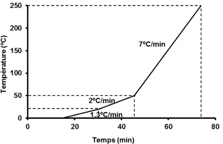
II. 4 - Conditions d’analyses ... 53
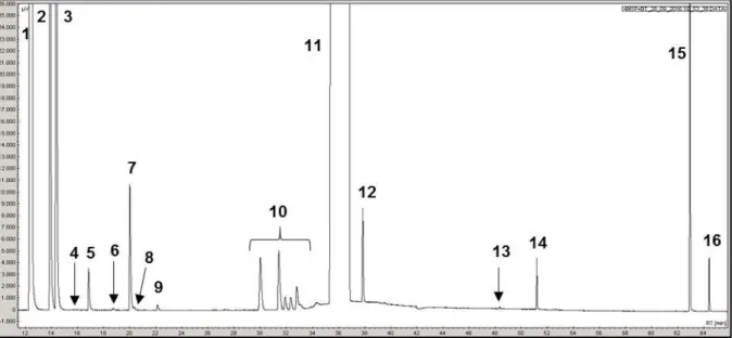
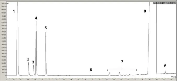
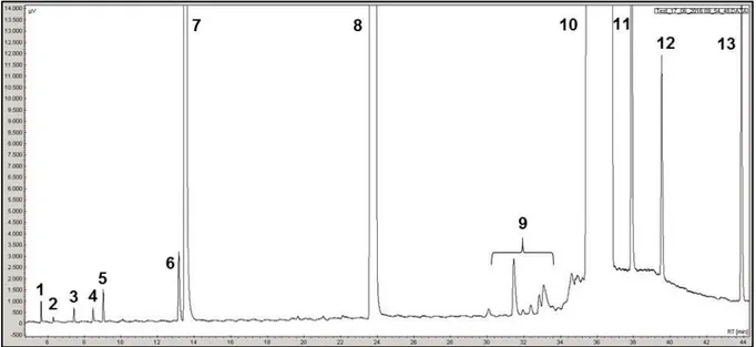
II. 4. 1 - Transformation des composés soufrés ... 54
II. 5 - Exploitations des résultats ... 66
III - MODELISATION CINETIQUE ... 68
III. 1 - Phénomènes en présence et simplifications ... 68
III. 2 - Phenomènes de diffusion ... 70
III. 2. 1 - Diffusion interne et module de Thiele généralisé ... 70
III. 2. 2 - Diffusion externe ... 73
III. 3 - Mise en œuvre dans le logiciel ReactOp Cascade 3.20 ... 73
IV - PRODUITS CHIMIQUES ... 75
CHAPITRE III : TRANSFORMATION DES COMPOSES SOUFRES SEULS ET EN MELANGE ... 77
I - TRANSFORMATION DES COMPOSES SOUFRES SEULS ... 79
I. 1 - Thermodynamique des réactions ... 79
I. 1. 1 - Transformation du 2-méthylthiophène ... 80
I. 1. 2 - Transformation du 3-méthylthiophène ... 82
I. 1. 3 - Étude thermodynamique pour la transformation du benzothiophène ... 84
I. 2 - Effet du temps de contact ... 85
I. 3 - Effet de la température ... 88
I. 4 - Effet de la pression partielle d’H2S et d’H2 ... 89
II - TRANSFORMATION DES COMPOSES SOUFRES EN MELANGE ... 92
II. 1 - Impact du BT et/ou 2MT sur la transformation du 2MT et/ou BT ... 92
II. 2 - Identification du réel inhibiteur ... 94
III - MODELISATION CINETIQUE ... 96
III. 1 - Détermination des paramètres d’adsorption d’H2S et d’H2 ... 102
III. 2 - Transformation des composés soufrés seuls ... 103
III. 3 - Analyse de sensibilité des paramètres ... 105
III. 4 - Modélisation cinétique des composés soufrés en mélange ... 107
IV - DISCUSSION ... 108
V - CONCLUSION ... 111
CHAPITRE IV : TRANSFORMATION DES COMPOSES OLEFINIQUES SEULS ET EN MELANGE AVEC LES COMPOSES SOUFRES ... 113
I. 1 - Thermodynamique ... 115
I. 1. 1 - Transformation du 4-méthylpent-1-ène ... 115
I. 1. 2 - Transformation du 3,3-diméthylbut-1-ène ... 121
I. 1. 3 - Transformation du hex-1-ène ... 122
I. 2 - Étude paramétrique ... 125
I. 2. 1 - Effet du temps de contact ... 125
I. 2. 2 - Effet de la température ... 130
II - TRANSFORMATION DES COMPOSES OLEFINIQUES EN MELANGE AVEC LES COMPOSES SOUFRES ... 132
II. 1 - Impact des composés soufrés sur la transformation des oléfines ... 133
II. 2 - Impact des oléfines sur la transformation des composés soufrés ... 140
III - MODELISATION CINETIQUE ... 142
III. 1 - Modélisation cinétique des composés oléfiniques seules ... 144
III. 2 - Modélisation cinétique des oléfines en mélange avec les composés soufrés ... 150
IV - DISCUSSION ... 153
V - CONCLUSION ... 161
CONCLUSION GENERALE ... 163
REFERENCES BIBLIOGRAPHIQUES ... 167
3
La croissance de la mobilité des personnes et des marchandises ainsi que celle de l’activité industrielle à l’échelle mondiale ont entrainé une forte augmentation de la pollution atmosphérique ces dernières décennies. Les gaz d’échappements automobiles y contribuent (sous forme de dioxyde de soufre) pour une part par la présence de soufre dans les carburants. Par ailleurs, le soufre présent dans les carburants est un poison pour les catalyseurs de dépollution automobile [1-3]. Ainsi, la production de carburants plus propres a été imposée aux raffineurs et a stimulé la recherche et les innovations dans les procédés d’hydrotraitement et les catalyseurs associés. La diminution de la teneur en soufre des coupes essence par hydrodésulfuration (HDS) est devenue essentielle pour répondre aux réglementations actuelles à travers le monde (10 ppmS en Europe depuis 2009) et à venir (par exemple en Chine V et US Tier : 10 ppmS en 2017).
Les efforts sur les carburants essences portent essentiellement sur les fractions essences issues du craquage catalytique (FCC) qui représentent seulement entre 30 et 40% en volume mais contribuent pour plus de 90% du soufre présent dans le mélange final [4]. Sachant que les essences contiennent une teneur en oléfines élevée (de 20 à 40% en volume), indispensable au maintien d’un bon indice d’octane [5] et que l’hydrodésulfuration (HDS) poussée des essences est réalisée sous pression d’hydrogène, il est par conséquent important de prévenir l’hydrogénation (HYD) des oléfines.
L’essence de FCC est un mélange complexe de plus 400 composés parmi lesquels les composés soufrés sont présents à travers diverses familles où les alkylthiophènes et les benzothiophènes correspondent à plus de 50% des composés soufrés totaux. Les oléfines sont principalement des C5 oléfines et C6 oléfines ramifiées ou linéaires.
La littérature rapporte des travaux sur la transformation de molécules modèles soufrées et oléfiniques seules. En revanche, peu relatent la transformation de composés soufrés en mélange et/ou en présence d’oléfines selon leur structure.
Par conséquent, il est important, de manière à optimiser le procédé d’HDS profond via l’utilisation de molécules modèles (soufrées et oléfiniques), d’identifier tous les phénomènes impliqués (compétition à l’adsorption à la surface du catalyseur, effet de la structure des molécules,…) de façon à acquérir les connaissances scientifiques indispensables à la compréhension des systèmes constitués par les charges réelles pour atteindre les normes fixées par les législateurs.
Dans ce contexte, les travaux effectués dans le cadre de cette thèse ont pour objectifs d’étudier par une approche à la fois expérimentale et théorique (modélisation cinétique) :
1/ La transformation de composés modèles soufrés représentatifs des familles contenues dans les essences de FCC. Les molécules modèles choisies sont le 2-méthylthiophène (2MT), le 3-méthylthiophène (3MT) et le benzothiophène (BT).
4
Les composés soufrés ont tout d’abord été étudiés seuls puis en mélange (BT et βMT) de manière à comparer leur réactivité et mettre en évidence les effets de compétition à l’adsorption entre eux à la surface du catalyseur. Ceci a permis d’identifier les molécules les plus réfractaires et/ou les plus inhibitrices. La modélisation cinétique a permis de valider les schémas réactionnels et chiffrer les phénomènes de compétition à l’adsorption.
β/ La transformation d’une charge modèle représentative d’une essence de FCC, c’est-à-dire constituée de molécules soufrées (BT ou 3MT) et de C6 oléfines dans des proportions représentives des essences.
Les oléfines étudiées sont des C6 oléfines (majoritaires dans les essences), c’est-à-dire, l’hex-1-ène, le 4-méthylpent-1-ène (4MP1N), le 3,3-diméthylbut-1-ène (33DMB1N) et le 2,3-diméthylbut-2-ène (23DMB2N). Celles-ci ont été choisies afin de mettre en évidence l’effet de la structure (position de la double liaison et ramification).
Tout d’abord, leur réactivité a été mesurée seule pour permettre d’établir une échelle de réactivité (en terme d’isomérisation et d’hydrogénation) selon leur structure. Leur réactivité a ensuite été mesurée en présence de molécules soufrées (3MT et le BT) de manière à comparer leurcomportement dans des conditions proches d’HDS d’une essence de FCC. L’ensemble de ces résultats a été chiffré et validé à travers un modèle cinétique unique.
Ce mémoire est divisé en quatre parties. Après avoir présenté les différents travaux de la littérature sur l’hydrodésulfuration d’essences de FCC (Chapitre I), nous avons rappelé les techniques expérimentales et analytiques (Chapitre II). Dans le Chapitre III, la transformation de molécules modèles soufrées (seules et en mélange) en présence du catalyseur CoMo/Al2O3 est présentée. Enfin, dans le dernier chapitre, la transformation d’une charge modèle représentative d’une essence de FCC c’est-à-dire constituée de 3MT ou de BT et de C6 oléfines de structures différentes a été étudiée.
5
7
In this chapter, we successively describe the ultra-deep HDS process to remove sulfur from FCC gasoline. Typical catalyst that allows an ultra-deep HDS of fuels is present as well as the techniques to improve its efficiency. Furthermore, the different model molecules, representative of sulfur compounds and olefins present mostly in the FCC gasoline are presented as well as their intrinsic reactivity and competitive reaction on the catalyst surface. This study is important to understand the interactions between those molecules on the catalyst surface and to determine the most refractory compounds. In addition, a kinetic modeling is reported in order to show theoretical approach for the transformation of those molecules as well as to compare the different models.
I - HYDRODESULFURIZATION PROCESS
I. 1 - Industrial hydrotreatment processThe industrial hydrotreatment processes has a key role in the oil industry with the aim to improve the fuels quality while conserving the limits imposed by different regulations worldwide [6]. Thus, these processes allows to eliminate heteroatoms such as sulfur (process known as hydrodesulfurization: HDS), oxygen (hydrodeoxigenation: HDO) or nitrogen (hydrodenitrogenation: HDN) through a catalytic treatment in presence of hydrogen. A typical industrial hydrotreatment process works in a fixed bed reactor operating in temperatures between 150ºC and 400ºC under hydrogen pressures varying between 1 to 10 MPa. However, these conditions could be adapted as function of the feed and the nature of the gasoline desired as final product. Thereby, the hydrodesulfurization of a gasoline, for example, leads to the cleavage of a C-S bond of an organ sulfur molecules to form hydrocarbons and hydrogen sulfide (Scheme I-1).
Scheme I-1. HDS of a methylthiophene molecule representative of a FCC gasoline [7].
The commercial gasoline comes from the treatment of crude oil by distillation, reforming, isomerisation or Fluid Catalytic Cracking (FCC) units (Scheme I-2). The FCC gasoline is produced by the refine of crude oil through the cracking of heavy into light molecules. The fraction of the crude oil is separated in various compounds based on physical properties, especially the boiling point, through a distillation column.
8
Scheme I-2. General representation of a refinery [8].
The FCC processes originated in 1928 patented by Eugene Houdry and it took a remarkable impulse in the industry with the Second World War due to the needs of gasoline and petrochemical materials. In the decade of 50s, Cole et. al. [9] and Casagrande et. al. [10] evidenced the importance to avoid the hydrogenation of olefins in order to maintain the high level of octane number in the fuel to maintain its detonation efficiency in the motor vehicles.
The desulfurization process of a FCC feed could be classified in two main groups: HDS based and the non-HDS based. The non-HDS based processes do not requires hydrogen to remove sulfur from the gasoline. On the other hand, the HDS based processes, consist in a combination of sulfur compounds and hydrogen to form the hydrogen sulphide (H2S) and organ compounds such as olefins, for example [12]. In parallel with the HDS, occurs the hydrogenation (HYD) of olefins into paraffins. This reaction represents a loss of octane number of the fuel and consequently a loss of the peak power. Therefore, there is a high appeal for developing catalysts with a high HDS/HYD ratio selectivity, which represent a high HDS activity and a low HYD activity.
I. 2 - Fluid Catalytic Cracking: origin and composition
The Fluid Catalytic Cracking (FCC) gasoline is a complex blend of more than 400 organic compounds with the sulfur compounds present in the form of mercaptans, thiophenes, derivate alkyl and benzothiophenes. However, the amount of sulfur compounds in the composition of gasoline, prior hydrotreatment, depends on the source of the oil and the refining scheme (i.e. presence of a FCC pre-treatment unit). Therefore, this composition could vary between 50 to 10000 ppm. The FCC gasoline represents 30-50 vol% of commercialized pool
9
of gasoline in Europe. However it contributes to over than 90% of all sufur contents present in the gasoline pool [11,12] (Table I-1).
1:MTBE: Methyl tert-buthyl ether
Table I-1. Composition of gasoline cut in the USA and Western Europe. [2,13-15].
This gasoline is produced by blending straight run naphtha, FCC naphtha and coke naphtha (Table I-1). The composition of a FCC gasoline varies depending on the feedstock and could be composed basically of paraffins and isoparafins (~30 wt%), olefins (~30 wt%), aromatic compounds (~30 wt%) and impurities such as sulfur compounds, in form of mercaptans, thiophenes, derivate alkyl and nitrogen compounds (Table I-2) [15-17].
Sample 1 Sample 2 Sample 3 Sample 4
Parafins 3.99 3.85 3.84 4.14 Isoparafins 25.67 24.18 22.37 24.56 C4= olefins 1.81 1.56 1.74 1.57 C5= olefins 12.71 11.79 10.45 11.69 C6= olefins 6.3 7.04 5.86 7.28 C7= olefins 6.19 5.08 4.6 4.96 C8= olefins 0.46 0.72 0.29 0.76 C9= olefins 0.65 0.22 0.15 0.15 Naphthenes 6.59 7.86 7.95 8.35 Aromatics 29.29 29.3 32.27 29.1 Unknown 6.34 8.22 10.42 7.29 Sulfur HC, ppm 77 165 1720 173
Table I-2. Composition of FCC gasoline from different feedstocks [16].
Furthermore, Magyar et. al [18] has shown that the amount of olefins present in a feedstock consist in majority by pentenes (such as 2-methylbut-2-ene and pent-2-ene) and hexenes (such as hex-2-ene, 2-methylpent-1-ene) (Table I-3).
Gasoline blend stocks
Percentage of gasoline pool in the US (%vol) Origin of Sulfur (%) Percentage of gasoline pool in western Europe (%vol) FCC gasoline 36 98 27 Naphtha reformate 34 - 40 Alkylate 12 - 9 Light straight-run naphtha 3 1 7.5 Coker naphtha 1 1 ~0 Hydrocracked naphtha 2 - ~0 Isomerate 5 - 10 Butanes 5 - 5.5 MTBE1 2 - 1
10
Olefins Conc. wt% Olefins Conc. wt%
t-but-2-ene 0.24 c-hex-2-ene 0.42 c-but-2-ene 0.32 t-hex-2-ene 0.75 Pentenes - c-hex-3-ene 0.37 Pent-1-ene 0.85 t-hex-3-ene 0.12 c-pent-2-ene 1.22 2-methylpent-1-ene 0.89 t-pent-2-ene 2.16 2-methylpent-2-ene 0.94 2-methylbut-1-ene 2.04 3-methylpent-1-ene 0.21 2-methylbut-2-ene 3.68 c-3-methylpent-2-ene 0.95 3-methylbut-1-ene 0.38 t-3-methylpent-2-ene 0.68 Hexenes - 4-methylpent-1-ene 0.13
Table I-3. Concentration of several olefins present in the FCC gasoline [18]
It is remarkable that in different feedstocks the amount of internal olefins present in the gasoline is higher than terminal olefins (Table I-4), which represents about 80% of C6 olefins present in the FCC gasoline.
Olefins Composition (% in total acyclic C6 olefins) Terminal Olefins Full Range Heavy A Heavy B
RCH=CH2 9.9 6.3 7.6 Hex-1ene 5.0 4.3 5.2 3-methylpent-1-ene 2.7 1.2 1.5 4-methylpent-1-ene 1.8 0.8 0.9 3,3-dimethylbut-1-ene 0.3 0 0 R1R2C=CH2 11.3 8.1 8.5 2-methylpent-1-ene 8.7 6.8 7.1 2,3-dimethylbut-1-ene 2.7 1.3 1.4 Internal Olefins R1CH=CHR2 40.0 40.9 41.8 trans-hex-2-ene 14.6 16.3 16.6
cis-hex-2-ene 8.4 9.9 10.0
trans-hex-3-ene 7.4 8.0 8.0
cis-hex-3-ene 2.6 2.6 2.9 trans-4-methylpent-2-ene 5.3 3.3 3.3 cis-4-methylpent-2-ene 1.7 0.9 1.0 R1R2C=CHR3 38.8 44.7 42.1 2-methylpent-2-ene 16.1 17.2 17.5 trans-3-methylpent-2-ene 13.9 17.7 15.5 cis-3-methylpent-2-ene 8.8 9.8 9.1
11
The octane number is a parameter linked with the capacity of fuel self-ignition in contact with air. The earlier self-ignition of the fuel in the piston of the motor vehicles – caused by a low octane number in the mixture - means a loss of peak power of the fuel and consequently a loss of efficiency. In the FCC gasoline, the main point of a successful hydrotreatment is to achieve a high HDS activity to remove the sulfur compounds from fuel and a low HYD activity, to avoid the hydrogenation of olefins and, consequently, decrease the octane loss in the final product.
To account for differences in the performance quality of a fuel, two parameters of octane number is used. The Research Octane Number (RON), which simulates the fuel performance under low severity engine operation and the Motor Octane Number (MON), which simulates the performance under more severe conditions. The octane number of the hydrocarbons pure and blending, reported in Table I-5, shows that the olefins has always a higher octane number (either MON or RON) than its hydrogenation products, pure and in bleeding.
Pure Compounds Blending
Parafins RON MON RON MON
n-butane 93 - 113 114 n-pentane 91 77 152 135 n-hexane 25 26 19 22 2,2-dimethylbutane 92 93 89 97 2,2,3-trimethylpentane 100 100 105 112 2,2,4-trimethylpentane 100 100 100 100 2-methylbutane 92 90 99 104 Olefins Pent-1-ene 91 77 152 135 2-methylbut-2-ene 97 85 176 141 3-methylpent-2-ene 97 81 130 118 2,2,4-trimethyl-1-pentene 100 86 164 153 2,2,4-trimethyl-2-pentene 100 86 148 139
Table I-5. Octane number of the olefins pure and blending (blending of 20% of the hydrocarbon in 80%vol of 60/40 iso-octane/n-heptane mixture) [20,21].
In the same way, the amount of sulfur compounds in the gasoline varies according with the feedstock. However it is well known that benzothiophene, C1-thiophenes and C2-thiophenes corresponds to more than 60% of the sulfur compounds present in a FCC gasoline (Table I-6) [22]. Despite the lower amount of mercaptans, thiophenes and tetrahydrothiophene in the mixture, those molecules have important impact on the formation of SOx gases formed by ignition of the fuel in the motor vehicles.
12
Sulfur Compounds Composition
ppm % Mercaptans 34 4.5 Thiophene 37 4.9 C1-thiophenes 106 14.1 Tetrahydrothiophene 24 3.2 C2-thiophenes 118 15.6 C3-thiophenes/thiophenol 76 10.1 C4-thiophenes/C1-thiophenol 83 11.0 Benzothiophene 276 36.6 Total Sulphur 754 100
Table I-6. Composition of sulfur compounds present in a FCC gasoline for a feed containing 1.05 wt% sulfur [22].
I. 3 - Regulation
The hydrodesulfurization (HDS) process is an important step in the refining industry. This process consists in the removal of sulfur to achieve the regulations imposed by European Union since 2009 and reinforced in the forthcoming China V and US Tier 3 regulations. This regulation imposes a 10 ppm maximum of sulfur compounds in 2017 [6]. Table I-7 report the evolution of the rules concerning the limit of different type of compounds in the fuels.
1998 2000 2005 2009
Sulfur ppm 500 150 50 -10 10
Benzene %vol max. 5 1 1 -
Aromatics %vol max. - 42 35 -
Olefins %vol max. - 18 18 -
Oxygen %pds max. 2.80 2.70 2.70 -
Table I-7. Evolution of the rules imposed in EU for different types of compounds in the fuel [23,24].
The content of sulfur compounds could vary greatly according to the origin of the crude oil (Table I-8). Therefore, the HDS process could vary depending on the sulfur specification of each region as well as the overall refinery configuration and the origin of crude oil, resulting in different amounts of sulfur compounds in the fuel after the hydrotreatment process [25].
13
Typical Feed Sulfur (wppm) Product Sulfur (wppm)
Western Europe 200 – 1000 10 - 20
North America 500 – 2000 30 – 50
South America 500 – 2000 30 – 100
Japan / Korea 50 - 200 10
Table I-8. Different sulfur contents in the feed of fuel depending on the region and the specification of sulfur amount on the final product [25].
I. 4 - Industrial hydrodesulfurization process of FCC gasoline
Currently, numerous works deals with the industrial processes for a deep desulfurization of FCC gasoline [12-15, 26-29]. Therefore, different strategies are adopted concerning the HDS of organic sulfur compounds to achieve the sulfur limit determined by the regulations by use a catalytic process:
Selective HDS preserving the octane number: Prime G+ Axens/IFPEN [12,30-32], SCANfining ExxonMobil [33-35], CD hydro + CDHDS from CD Tech [12,15]. HDS of organic sulfur with recovery of octane number by conversion of paraffins:
OCTGain ExxonMobil, UOP-IσTERVEP’s ISAL [15].
Polar adsorption by using solid adsorbent based on alumina (Black and Veatch Prichard IRVAD) [15].
Non-HDS process by capture of sulfur using reactive adsorption by solid adsorbent at elevated temperatures and low H2 pressure (Philips Petroleum S-Zorb Gasoline) [15].
Table I-9 reports a resume of different technologies and their respective representatives for the hydrodesulfurization processes. However, the most common method to sulfur removal is the post-treatment process of selective HDS maintaining the octane number, particularly the Prime G+ and SCANfinning ExxonMobil processes.
14
Technology Principle of Desulfurization Representative
Selective HDS
Improve the selective of
desulfurization, or passivate olefin hydrogenation
IFP’s Prime G+ [31] Exxon Mobil’s SCAσfining
[33] RIPP’s RSDS [36] FRIPP’s τCT-M and FRS [37] HDS processes with octane recovery or compensation
Deep HDS, saturate olefins, convert low-octane components to high-octane components
Exxon Mobil’s τCT-Gain UOP-IσTEVEP’s ISAL[13]
RIPP’s RDτS [38] FRIPP’s τTA [39] Catalytic
distillation
Distillation column; separately treated
fractions CDTech [15]
Others
Polar Adsorption Black and Veatch Pritchard’s IRVAD [15] Extrative Distillation GT-Desulf (GTC) [40] Polymer membrane Grace’s Brane [15] Table I-9. Resume of technologies using different principles for the HDS of sulfur compounds in the fuels [41].
Prime G+ Axens/IFPEN
The Prime G+ selective HDS process is the leading technology to achieve FCC gasoline post-treatment [25]. The Prime G+ Axens/IFPEN process has three main steps (Scheme I-3): the selective hydrogenation unit (SHU), a splitter (which separates the light from the medium and heavy naphtha) and a selective HDS unit in two stages for the treatment of the medium and heavy cracked naphtha [12].
Three main reactions occurs in the SHU unit:
Selective hydrogenation of diolefins (represent 0.5 to 2% of FCC gasoline), Isomerization of the olefins double bond,
Conversion of light mercaptans into heavy boiling sulfur compounds.
The SHU unit, through the elimination of diolefins, avoid the HDS catalyst deactivation since these kind of compounds could coke on the catalyst surface resulting in catalytic deactivation [42]. Moreover, the olefin double bond isomerization reduces the amount of terminal olefins. Transforming those olefins into thermodynamics equilibrium products in the mixture, producing higher octane olefins once internal olefins have a better RON than terminal olefins [43]. Finally, the conversion of light mercaptans into heavy boiling sulfur compounds in the SHU unit allows to reduce the amount of sulfur compounds in the low boiling range.
15
The combination of the splitter and the SHU unit before the selective HDS unit will produce a low sulfur Light Cut Naphtha (LCN) stream that is rich in C5 olefins and a Heavy Cut Naphtha (HCN) containing heavier sulfur compounds. This allows to preserve the valuable and reactive olefins (C5) from hydrogenation and recombination reactions. The HCN cut will be hydrotreated in two HDS stages to remove sulfur at the limit specified while preserving a minimal octane loss. Moreover, these units minimize the recombination of mercaptans and avoid the cracking reactions which means nearly 100% liquid yield [12]. Two catalytic bed are necessary to achieve these aims (catalysts based on cobalt-molybdenum and nickel). In the first HDS stage, the CoMoS catalyst acts in the heavy desulfurization with a minimum hydrogenation activity while in the second stage, the Ni catalyst was designed to exhibit virtually no hydrogenation activity and to displace the thermodynamic equilibrium of mercaptans produced in the first HDS stage.
Scheme I-3. General representation of the Prime G+ Axens/IFPEN process [25]. SCANfining ExxonMobil Process
The SCANfining ExxonMobil Process [12,15,34,35,44] was invented by Exxon Research and Engineering and Akzo Nobel who jointly developed a selective HDS catalyst (RT-225) for this purpose [26].
The SCANfining process (Scheme I-4) is composed of three main steps: the treatment unit, the HDS unit and the separator unit. The naphtha feed is introduced in the pre-treatment reactor in presence of H2 to saturate the diolefins. Otherwise, the diolefins could cause fouling in the heat exchange as well as in the HDS unit. The mixture hydrocarbon/hydrogen is then heated again and forwarded to the HDS unit containing the RT-225 catalyst, where the sulfur removal occurs while preserving the octane number. The desulfurized naphtha is then cooled and fractionated by a separator unit which can produce the light cuts and low sulfur naphtha as final products.
16
Scheme I-4. General representation of the SCANfining ExxonMobil process [35] CD hydro + CDHDS Process (CD Tech)
This process combines separation of FCC gasoline in several fractions through distillation and catalytic HDS (Scheme I-5). In this process, developed by CDTech, two distillation columns are loaded with desulfurization catalysts. The feed containing the FCC C5 + gasoline and hydrogen is introduced in the first distillation column (CDHydro) to remove sulfur from the LCN (lighter compounds of FCC gasoline) cut. In the CDHydro column, mercaptan reacts with diolefins to produce heavier sulfur compounds, which are the feed of the CDHDS column [15]. In this process, the operating conditions are optimized to maintain the olefins at the top of the column, at a relatively low temperature, and thus minimize the yield and consequently the octane loss. On the other hand, the sulfur compounds are stocked in the bottom part of the column under severe HDS conditions. Therefore, this setup achieves to produce an ultra-low sulfur amount in the fuels with a minimal olefins saturation.
Scheme I-5. General representation of CDHydro + CDHDS from CDTech for HDS of a FCC gasoline [15].
17
II - HYDROTREATMENT CATALYSTS
II. 1 - Generalities
Due to the presence of sulfur compounds, hydrotreatment process needs specific catalysts that combines high thioresistance and catalytic activity. In this regard, hydrotreating catalysts are usually in form of transition metal sulfides (TMS) such as molybdenum and tungsten (VIB group) promoted by elements of VIIIB group such as nickel or cobalt and supported on alumina, silica or aluminodilicates [45]. Thus, usual industrial catalyst for the hydrodesulfurization processes are the molybdenum sulfide catalysts promoted by nickel or cobalt, depending on the feed to be hydrotreated, with a Co(Ni)/[Co(Ni)+Mo] molar ratio of 0.3-0.6 [46]. An initial step is necessary to activate these type of catalysts. Thus, the sulfidation process could be make in the presence of H2S [47] or sulfur compounds such as thiophene and dimethyldisulfure [48]. This is a determining step to the formation of a stable active phase for hydrotreatment, conditioning a high catalyst life [49].
II. 2 - Catalyst Structure
The model catalyst structures evolved greatly along the years. The first structure model proposed a non-promoted catalyst based on the molybdenum sulfide. This stoichiometry is close to two atoms of sulfur for one atom of molybedum (MoS2) [8]. The molybdenum sulfide crystallizes in a hexagonal system with Mo2+ cations at the center of a trigonal prism formed by 6 sulfur atoms S2-. This geometrical units suggests the slab structure type “SMoSSMoS”. Then, the MoS2 slabs interacts between then by Van der Waals forces. In general, the active sites are composed of molybdenum atoms containing coordination unsaturations (called CUS: Coordinately Unsaturated Site), which are placed in the edges of the MoS2 slabs [50]. This theory was based on a fundamental approach suggested by Siegel [51] for the oxides catalysts. The importance of the anionic gaps was highlighted by Kasztelan et. al. [52] for the works with cis-penta-1,3-diene.
The hydrotreatment catalysts has evolved from the 90s up to nowadays and different models are proposed by the literature. Daage et. al. [53] proposed a bulk catalyst known as rim/edge model of a non-promoted MoS2 catalyst (Scheme I-6). This model was studied with dibenzothiophene (DBT) as model molecule and the authors have shown the relation between the catalytic activity and the coexistence of two different sites (the rim sites, located at the edge of exterior layer and the edge sites, located on the interior layers). Moreover, they observed that the hydrogenation (HYD) reactions of DBT took place on the rim sites, while the hydrodesulfurization (HDS) occurred on the edge sites. According to this model, the HDS and HYD selectivity could be optimized by modifying the catalyst structure. Berhault et. al. [54] and De La Rosa et. al. [55] studied the importance of support interaction with the active phase of a rim/edge MoS2 catalyst model. Whatever the strong or weak interaction with the support,
18
the proportion of stacked particles remained low. This suggested that the single layered morphology of commercial supported HDS catalyst was largely predominant on a MoS2 catalyst.
Scheme I-6. Rim/edge model of a MoS2 catalyst [53].
To increase the catalytic activity, the MoS2 catalyst is promoted by a metal, usually cobalt or nickel for the hydrotreatment catalytic processes. Different authors proposed models to describe the promotion effect of those metals. Schuit et. al. [56] proposed a model for a molybdenum sulfide catalyst promoted by cobalt which consist in a presence of a layer MoS2 on the surface of a cobalt support. Later, Farragher et. al. [57] proposed a pseudo-intercalation model (or surface intercalation) where the promoter such as cobalt is present only in the edge of the layer of MoS2, as reported in the Scheme I-7.
Scheme I-7. Intercalation model for a CoMoS catalyst [57].
A synergic model was proposed to describe the catalyst support of a MoS2 catalyst promoted by cobalt [58]. This model proposes the coexistence of MoS2 and Co9S8 crystallites on the support (Scheme I-8). Through a spill-over phenomena, the hydrogen activated on Co9S8 could be transfered for MoS2 sites.
Scheme I-8. Synergic model of a supported CoMo catalyst [58].
Posteriorly, Topsɵe et. al. [8] proposed the model of a mixed Co-Mo-S phase, which consist in an active site constituted by MoS2 sheets promoted by cobalt at the edges of the slabs.
19
According with Scheme I-9, the sulfide phases of MoS2 and Co9S8 are well dispersed over the alumina (Al2O3) support with a strong interaction between the alumina support and cobalt due to tetrahedral and octahedral sites on the catalytic support. Moreover, Kasztelan et. al. [59] proposed that the cobalt was located at the edge of the MoS2 single slabs which leads to a bulk promotor sulfide after saturation.
Scheme I-9. Phase mixed model of CoMoS catalyst [60].
The morphology of an unsupported catalyst promoted by nickel and cobalt was studied by Raybaud [61] and Lauritsen et. al. [60] through the Density Function Theory (DFT) and Scanning Tunneling Microscopy (STM) techniques. From this technique, it is possible to highlight the existence of different MoS2 and CoMoS phases (Scheme I-10). A near-hexagonal shape for Co-Mo-S was observed which implies two types of low-indexed edge terminations exposed in the clusters. The shape of the slabs, following the Wulff-theorem, is determined by the competition between two low index MoS2 edge, referred as the ( 010) edge known as S-edge and the (10 0) S-edge known as M-S-edge (Scheme I-11).
20
Scheme I-11. Hypothetical hexagonal MoS2 nanocluster model representation for a CoMoS catalyst [60].
Furthermore, Moses et. al. [63] proposed that the HDS activity takes place on the Coordinately Unsaturated Sites (CUS). These sites, which are deficient in electrons (acid sites of Lewis) interact with electron donating compounds removing the sulfur. This theory could be confirmed by Prins et. al. [64] who indicates that the metal-sulfur bond between the molybdenum and sulfur atom implies an electronic interaction. Thus, this interaction of the metal with the thiophene orbital weakens the C-S bond and consequently cause its rupture. The contribution of the promoter electronic density through the promoted metal allows to explain the promotion electronic origin. Furthermore, modeling approaches realized by Raybaud et.al. [65-67] and Paul et. al. [68-70] have shown that the morphology of the MoS2 slabs and stability of the sites in the catalytic edges are sensitivities to the sulfidation conditions, especially the ratio PH2S/PH2. These conclusions could be confirmed by Lauritsen et. al. [60] concerning the impact of partial pressure on the slabs nature.
Moreover, Raybaud et. al. [65-67] realized a modeling ab initio and, in combination with thermodynamic and micro-kinetic models, established the morphology for an active phase of a non-promoted catalyst (MoS2) as well as a promoted catalyst such as CoMoS (where the promoter is present only on S edge) and NiMoS (where the promoter is present on the S and M-edges). The morphology of these active sites could be confirmed by Sun et. al. [71] who realized a theoretical investigation of the MoS2 catalysts as well as the effect of Ni and Co as promoter (Table I-10).
Phase MoS2 Co-Mo-S Ni-Mo-S
Shape 93 - 113
Promoter location 91 77 152
S of M-edge coverage (%) 25 26 19
S of S-edge coverage (%) 92 93 89
21
Scheme I-12. Phases morphologies from DFT calculations for different catalysts a) MoS2 non promoted, b) CoMoS and c) NiMoS [66,67].
Furthermore, the detailed analysis of full reaction pathway of the first sulfur vacancy creation is kinetically more favorable on the M-edge than on the S-edge (Scheme I-13) [61]. Moreover, this sulfur content on the M-edge proves that the hydrogen dissociation is the limiting step for the transformation of the sulfur compound with an activation energy about 1.0 eV.
Scheme I-13. Reaction pathway for the formation of the first sulfur vacancy on the Mo-edge [61].
These results were completed by Krebs et. al. [72,73] through a DFT calculation to analyze the origin of hydrodesulfurization/hydrogenation selectivity of 2-methylthiophene and 2,3-dimethylbut-1-eneover Co(Ni)MoS active phase. Indeed, they agreed that the morphology and the active phases diagrams (Scheme I-14) are as function of sulfur-reducing properties and the nature of promoter. From these calculations, Raybaud [61] could determine a chemical potential s equal to 0.9 eV under 400 °C and PH2S/PH2 = 0.05. This means that in typical HDS conditions, the lower edge energy is when Mo and S-edges are 50% sulfur covered.
22
Scheme I-14. Chemical potential as function of temperature and PH2S/PH2 ratio [61].
III - HYDRODESULFURIZATION
AND
HYDROGENATION
OF
MODEL FEED OF FCC GASOLINE
The key point to produce a gasoline with high octane number and low amount of sulfur compounds in its composition is to understand the reaction mechanism involved in the hydrodesulfurization (HDS) and hydrogenation (HYD) reactions. Another important point is to understand the factors that influence the HDS/HYD selectivity (an important ratio that correlates the HDS of sulfur compounds and the HYD of olefins) such as modification of active phase and catalyst support. Numerous works approach the reactivity of real feed [74] and model molecules [18,75-80] to understand and optimize the hydrotreatment process.
In order to be representative of a real process - taking account the complex mixture present in a real FCC gasoline - it is necessary to study the mechanisms and reactivity of model molecules representative of a real feed. Thus, the model molecules representative for the sulfur compounds present in the FCC gasoline are alkyl thiophenes (2-methylthiophene: 2MT and 3-methylthiophene: 3MT) and benzothiophene. On the other hand, the olefins representative of a real feed are often represented by C6 olefins such as 2,3-dimethylbut-2-ene (23DMB2N), 3,3-dimethylbut-1-ene (33DMB1N), hex-1-ene, 4-methylpent-1-ene (4MP1N).
III. 1 - Hydrodesulfurization of sulfur compounds
Mey et. al. [81] proposed a reaction scheme (Scheme I-15) for the transformation of 2MT as model molecules (T = 200ºC, P = 20 bar, CoMo/Al2O3). This study involves a series of consecutive reactions through two main pathways: Direct Desulfurization (DDS) of 2MT for the formation of pent-1,3-diene as intermediate, which then produce pentenes (pent-1-ene and pent-2-ene) through hydrogenation reaction. The hydrogenation of these pentenes leads then to the formation of pentane as final product. Another pathway involves the hydrogenation of 2MT into 2-methyltetrahydrothiophene (2MTHT) followed by a C-S cleavage and opening of cycle
23
into the intermediates pent-1,3-diene and pentenes and then through hydrogenation reaction to form the n-pentane. This reaction scheme could be confirmed by Zhao et. al. [82] and Pelardy et. al. [83] under similar operating conditions.
Scheme I-15. Transformation of 2MT (T = 200ºC, P = 20bar, CoMo/Al2O3) [81]. Such as 2MT, two main pathways may explain the transformation of 3-methylthiophene [78]: the direct desulfurization (DDS) and the partial hydrogenation (HYD) routes, which makes the first C-S bond cleavage possible through a -elimination (Scheme I-16). According to this scheme, 3MT would be first hydrogenated to 3-methyl-dihydrothiophene (3MDHT), which would subsequently leads to the formation of 3-methyltetrahydrothiophene (3MTHT) and then the opening of the ring with the rupture of C-S bond. The result of this HYD route is the formation of 2-methyl-1-butanethiol (2M1BT), methyl-1-butanethiol (3M1BT) and 3-methyl-2-butanethiol (3M2BT). Furthermore, the HDS reaction of these molecules leads to the formation of pentenes such as 2-methylbut-1-ene (2MB1N), 2-methylbut-2-ene (2MB2N) and 3-methylbut-1-ene (3MB1N). The DDS route could not be prove since there was no traces of isoprene in their experiments.
Scheme I-16. Transformation of 3MT (T = 250ºC, P = 20 bar, CoMo/Al2O3) [78]. Van Parijs et. al. [84] and Devanneaux et at. [85] suggested a reaction scheme (Scheme I-17) for the HDS of benzothiophene (BT) based on their experiments at P = 30 bar and T = 513-573 K over a CoMo/Al2O3 catalyst. Two main pathways were proposed: the hydrogenation
24
of BT into its intermediate dihydrobenzothiophene (DHBT) and then the HDS reaction for the formation of ethylbenzene (EB) as final product. The EB could also be formed from the DDS of BT, which represents the second pathway proposed. Wang et. al. [86] suggested a parallel desulfurization of BT and DHBT to form EB through the intermediate styrene (ST) as reported in Scheme I-18 (P = 50 bar and T = 300ºC, MoS2/Al2O3 catalyst). Thus, as the BT possesses an aryl C-S bond and a vinyl C-S bond, the cleavage of the double bond occurs by hydrogenolysis reaction to form ST. In addition, starting from DHBT, Wang observed the formation in small amount of octahydrobenzothiophene (OHBT), 1-ethylcyclohexene (ECH) and 3-ethylcyclohexene. However, at their operating conditions, the hydrogenation of DHBT is much less favored than the hydrogenation of BT. This factor could confirm the main transformation route was the HYD of BT into DHBT and then the HDS of DHBT to form EB.
Scheme I-17. Transformation of BT (T = 260ºC, P = 4.8-30 bar, CoMo/Al2O3) [84].
Scheme I-18. Transformation of BT (T = 280ºC, P = 50 bar, CoMo/Al2O3) [86].
Numerous papers report the relative reactivity of sulfur compounds under FCC conditions and there is no paper in the literature concerning the competitive reactions between the sulfur compounds on the CoMo/Al2O3 catalyst surface, which could represent the real feed.
25
Regarding the relative reactivities of the sulfur compounds (2MT, 3MT and BT), Hatanaka et. al. [4,87] has shown that benzothiophene was more reactive than methylthiophenes under their operating conditions (T = 130-230ºC, P = 13 bar, CoMo/Al2O3) (Figure I-1a). Furthermore, Desikan et. al. [88] reported that 3MT is considerably more reactive than 2MT and thiophenes at 305 and 414ºC and 1 atm over CoMo/Al2O3 (Figure I-1b). Otherwise, Song et. al. [15] proposed, qualitatively, a contrary order of reactivity for these compounds with thiophenes as the highest reactivity in comparison with benzothiophenes and dibenzothiophenes (Scheme I-19).
Figure I-1. Reactivity comparison of individual sulfur compounds a) Hatanaka et. al. [87] (P = 13 bar, CoMo/Al2O3) and b) Desikan et. al. [88] (T = 305 and 414ºC, P = 1 atm, CoMo/Al2O3).
26
On the other hand, many papers described the effect of H2S on the transformation of sulfur compounds. This product could compete on the active sites of the catalyst with the sulfur model molecules and inhibit its transformation since it is a co-product of the HDS reaction. Therefore, it is important to study the impact of H2S on the transformation of model molecules under FCC operating conditions. Thus, Fontaine et. al. [75] has shown an inhibiting impact due to the presence of different amount of H2S (from 200 up to 1100 ppm) on the transformation of 2MT at 250ºC, P = 20 bar (Figure I-2). This effect was observed since as higher is the amount of H2S introduced lower is the synergy coefficient for the CoMo and NiMo catalyst. On the other hand, for the MoS2 catalyst, no effect of H2S on the transformation of 2MT was noticed.
Figure I-2. Effect of H2S on the transformation of 2MT over different catalysts (T = 250ºC, P = 20 bar, H2/feed = 360 NL/L) [75].
The same effect was observed by Dos Santos et. al. [78] for the transformation of 3MT over CoMo/Al2O3 catalyst at 185ºC and 20 bar (Figure I-3). This effect could be noticed through the decrease in the kinetic apparent constants as function of the amount of H2S introduced in the reactor. This effect could be explained by a competitive adsorption between 3MT and H2S on the active sites. On the other hand, the amount of 3-methyltetrahydrothiophene (3MTHT) increased with the amount of H2S introduced. This could be due to an inhibiting effect of H2S for the C-S bond cleavage. Regarding the hydrocarbons products, the formation of the pentane or pentenes was inhibited by H2S, since their apparent kinetic constant decreased with the increase in H2S partial pressure.
27
Figure I-3. Effect of H2S on the transformation of 3MT (T = 180ºC, P = 20 bar, CoMo/Al2O3) [78].
These results are in agreement with Olguin Orozco et. al. [89], who studied the effect of the H2S partial pressure on the transformation of dibenzothiophene over MoS2 catalyst at 250ºC and 45 bar. Prins et. al. [] also analyzed the inhibition of H2S on the HDS of 4,6-dimethylbenzothiophene over a σiMoS/ -Al2O3 and Pd/ -Al2O3 (T = 300ºC, P = 50 bar) and observed an inhibiting effect of H2S due to competitive reactions between the reactants on the catalytic surface.
In addition, Morales-Valencia et. al. [91] studied the influence of different olefins (Table I-11) on the HDS of 2MT over CoMo/Al2O3 catalyst at 270ºC and 50 bar and observed an inhibiting effect of all types of olefins on the HDS of 2MT (Table I-12). In presence of 2,5-dimethyl-2,4-hexadiene, the conversion of 2MT dropped from 60% to 44% with 1.2wt% of olefin and 22% with 3wt% of the same olefin. On the other hand, the selectivity of HDS products was not significantly affected by the presence of olefins (Table I-12). Furthermore, it was observed that, in spite of a higher concentration of 2,2,4-trimethyl-1-pentene and 2,4,4-trimethyl-2-pentene (TMPs) olefins (11.5wt%), the inhibiting effect of these olefins were slightly higher than oct-1-ene (5wt%). Thus, the oct-1-ene has a stronger inhibiting effect on the transformation of 2MT than TMPs olefins. This effect could be explained by the higher adsorption of oct-1-ene on the active sites. In conclusion, a branched olefin had a weaker inhibiting effect on the HDS of 2MT than a non-branched olefin such as cyclohexene and oct-1-ene. Thus, the order of inhibition effect achieved increased as follows: cyclohexene 2,4C6diene > oct-1-ene > TMPs.
28
Feed %C-2MT Selectivity of 2-MT products
2MTHT 1,3-Penta 2Pentene 1Pentene Pentane
1 60 7 19 34 13 27 2 44 5 20 40 9 26 3 22 6 21 41 11 21 4 20 15 23 36 15 11 5 15 19 23 33 17 8 9 37 11 22 34 15 18 10 39 6 22 37 14 21
Table I-12. Effect of different feeds on the 2MT conversion and selectivity [91].
Furthermore, Dos Santos et. al. [78] observed that the hydrodesulfuruzation of 3MT was greatly inhibited by the presence of hex-1-ene, since the apparent rate constant of HDS reaction decreased from 4.4 to 2 L.h-1.g-1 when the hex-1-ene partial pressure increased in the mixture (Figure I-4).
Figure I-4. Apparent rate kinetic constant for HDS of 3MT as function of hex-1-ene. (T = 180ºC, P = 20bar, CoMo/Al2O3). [78].
III. 2 - Hydrogenation of olefins
Numerous studies deals with the hydrogenation reaction of the olefins alone [18,19,77,79] or in a mixture with sulfur compounds [17,75,78,92,93] under industrial operating conditions in order to understand the reactivity as well as to identify the reaction scheme of model olefins representatives of a FCC gasoline.
Mey et. al. [81] and Daudin et. al. [77] studied the transformation of 23DMB2N in presence of 2MT at 250ºC and under 20 bar and could propose a reaction scheme for the transformation of 23DMB2N (Scheme I-20). The main products is the 2,3-dimethylbut-1-ene (23DMB1N) as isomerisation product and 2,3-dimethylbutane (23DMB) as hydrogenation product. Furthermore, a fast thermodynamic equilibrium between 23DMB2N and 23DMB1N is established with a proportion of 70% of 23DMB2N and 30% of 23DMB1N. Moreover, it
29
was demonstrated through the modeling calculations, that the hydrogenation product (23DMB) is formed mainly from 23DMB1N, which has a final double bond instead of 23DMB2N with an internal double bond [81]. Finally, the minorities products produced is the results of skeletal isomerisation and represents less than 2% of all products formed on the transformation of 23DMB2N. Furthermore, Pelardy et. al. [76] has noticed a mutual inhibiting effect between 2MT (0.3 wt%) and 23DMB2N (20 wt%) (CoMo/Al2O3, T = 250ºC, P = 20 bar) due to competitive adsorption. However, taking account the different amount of each molecule, the inhibiting effect of 2MT on the transformation of 23DMB2N seems to be more important than the opposite. This conclusion could be made since the apparent rate constant alone (k0)/apparent constant ratio in mixture (kmix) of 2MT is about 2 times higher than for olefin (k02MT/kmix2MT = 2.9 ; k0ole/kmixole = 1.5). This effect could be explained by Krebs et. al. [94] through DFT calculations, where 2MT is more adsorbed by about 0.9 eV on the catalytic edge than 23DMB1N. Furthermore, at M-edge, the strongly adsorption of 2MT is due to the presence of S-atom (interaction of electronic pair with Lewis M-sites), whereas the electrons from 23DMB1N could not interact easily with the Co sites.
Scheme I-20. Transformation of 23DMB2N (T = 250ºC, P = 20 bar) [77].
In the same way, it is important to quantify the effect of H2S on the transformation of the olefins since H2S is a co-product of a HDS reaction. Thus, could affect positively or negatively the HYD of olefins when is analyzed in mixture with the sulfur compounds. Therefore, Lamic et. al. [95] observed a decrease on the catalytic activity for the transformation of 23DMB2N (T = 250ºC, P = 20 bar) due to the presence of H2S over an unsupported CoMoS and NiMoS (Figure I-5). This loss of hydrogenation activity was more pronounced for unsupported NiMoS than CoMoS and MoS2 catalyst (which there is no effect due to the amount of H2S introduced), especially at low concentration of H2S. This effect shows that the
30
unsupported NiMoS catalyst is more sensitive to the partial pressure of H2S than CoMoS catalyst. In spite of CoMoS catalyst is more selective than NiMoS, the highest sensitivity of NiMoS catalyst with H2S could improve the HDS/HYD selectivity closer than CoMoS catalyst for a high sulfur amount feeds.
Figure I-5. Impact of H2S on the catalytic activity of CoMoS, NiMoS and MoS2 (T = 250ºC, P = 20 bar) [95].
Several works deals with the transformation of hex-1-ene as model molecule to study its transformation alone [96] and in presence of a sulfur compounds [78,92,97-99]. Tu et. al. [92] established a reaction scheme for the transformation of hex-1-ene over a CoMo/Al2O3 catalyst at 195-285ºC and 16 bar in presence of H2S, 2MT and 3MT. Therefore, the transformation of hex-1-ene leads to the formation of n-hexane, 2 and 3-hexenes and thiols as described in Scheme I-21 through two main pathways: the isomerization of hex-1-ene into 2 and 3-hexenes and then by hydrogenation reaction to form n-hexane or through the direct hydrogenation of hex-1-ene into n-hexane. Furthermore, the isomerization reaction is the fastest transformation of hex-1-ene, thus the hydrogenation and recombination reactions occurs once the thermodynamic equilibrium between the isomers was achieved.
Moreover, it was noticed an inhibiting effect on the hydrogenation of hex-1-ene caused by the presence of the sulfur compounds studied (Figure I-6a). According with these results, the HYD activity is retarded following the order: H2S > thiophene > 3-methylthiophene > 2-methylthiophene. This order could be confirmed by the apparent kinetic rate as reported Figure I-6b.
31
Scheme I-21. Transformation of hex-1-ene (T = 180ºC, P = 20bar, CoMo/Al2O3) [78].
Figure I-6. Effect of sulfur compounds on the hydrogenation of hex-1-ene. a) as function of temperature and b) apparent kinetic constant as function of sulfur content.(T = 195-285ºC, P = 16 bar, CoMo/Al2O3) [92].
These results could be confirmed by Dos Santos et. al. [78] which notice a considerably effect of 3MT on the transformation of hex-1-ene through the decrease of apparent kinetic constant as function of 3MT concentration (Figure I-7). However, it was concluded that the effect of 3MT on the HYD reaction is due to the H2S produced by the HDS of 3MT and not due to 3MT itself. These theory is supported by Tu et. al. [92] and explained by the fact of H2S could easily be adsorbed on Mo CUS (Coordinately Unsaturated Sites) of the sulfide hydrotreatment catalyst due to its high adsorption on the catalytic surface.
Additionally, Si et. al. [100,101] studied the effect of H2S on the transformation of hex-1-ene over a NiMo/Al2O3 catalyst at 200ºC and 2 MPa of pressure by varying the amount of H2S and observed an inhibition effect of H2S on the hydrogenation and isomerisation of hex-ene. Furthermore, a recombination reaction of hex-ene and H2S was observed to produce 1-hexanethiol and 2-1-hexanethiol, which increase with the content of H2S injected. Indeed, the concentration of hydrogenation (Figure I-8a) and isomerisation (Figure I-8b) products decrease, meanwhile the concentration of hex-1-ene increase considerably as function of the amount of H2S introduced.
32
Figure I-7. HYD apparent kinetic constant as function of 3MT partial pressure (T = 180ºC, P = 20bar, CoMo/Al2O3) [78].
Irvine et. al. [102] studied the transformation of 3,3-dimethylbut-1-ene (33DMB1N) over a standard -alumina catalyst at T = 150°C. They observed the formation of 23DMB2N and 23DMB1N as isomerization products from the transformation of 33DMB1N. In all cases a fixed product ratio between them was observed, which confirms a thermodynamic equilibrium between the isomers. The skeletal isomerization of 33DMB1N could through two possible mechanisms (Scheme I-22).
Scheme I-22. Possible mechanisms for the isomerization of 33DMB1N [102]. Figure I-8. Impact of H2S on the transformation of hex-1-ene a) HYD reaction and b) isomerisation reaction (T = 200ºC, P = 20 bar, NiMo/Al2O3) [100].
33
In the first possible mechanism (1), the alkene is protonated on the catalytic surface and then, the proton, either from Brønsted acid sites or from adsorbed alkene, pass through a methyl migration, losing the proton to form either 23DMB2N or 23DMB1N. The second mechanism involves the adsorption of 33DMB1N in the Lewis acid site and then, through a rearrangement of groups release the isomerization product (23DMB1N). Furthermore, Karmal et. al. [103] observed that over an unsupported CoMo catalyst, the isomerization activity of 33DMB1N is significantly lower than over a supported catalyst. This proves that the isomerization of 33DMB1N is likely achieved through the pathway 1 (Scheme I-22), since the protons necessary for the isomerization of 33DMB1N are mainly found on the catalyst support. Nevertheless, the main isomerization pathway does not exclude the reaction on the sulfides, since the heterolytical dissociation of H2S on the Mo vacancies is the cause of the protons production. The acid sites would be much more fragile than those obtained by the catalyst support.
Furthermore, Badawi et. al. [104] studied the transformation of 33DMB1N over CoMo/Al2O3 and NiMo/Al2O3 catalysts at 150ºC and atmospheric pressure with a H2/olefin ratio equal to 36. In these conditions, the transformation of 33DMB1N occurs through two main pathways (Scheme I-23): the HYD pathway and the ISO pathway. In the first pathway, a direct hydrogenation leads to the formation of the main HYD product: 2,2-dimethylbutane (22DMB), meanwhile the ISO pathway leads to the formation of 23DMB2N and 23DMB1N through a skeletal isomerization of 33DMB1N and then through the HYD of 2,3-dimethylbutenes isomers, the formation of 2,3-dimethylbutane (23DMB).
Scheme I-23. Transformation of 33DMB1N (T = 150ºC, P = 1 atm, CoMo/Al2O3) [104]. There is no data in the literature concerning the transformation of 4-methylpent-1-ene over CoMo/Al2O3 catalyst under FCC operating conditions. However, Toba et. al. [19] compared the reactivity of different olefins over a CoMoP/Al2O3 catalyst, T = 319 ºC and P = 1 MPa in order to show the effect of the olefin structure. Therefore, the conversion of olefins decreased following the order: RCH=CH2 > R1R2C=CH2 > R1CH=CHR2 > R1R2C=CHR3, which means for example: 4-methylpent-1-ene > 23DMB1N > trans-hex-2-ene > 2-methylpent-2-ene. These results are in agreement with Mey et. al. [81], which concluded that terminal olefins are more reactive than internal olefins.
34
Pérot et. al. [105] has shown that the hydrogenation activity of propene and cyclopentene over MoS2 catalyst promoted by cobalt or nickel is about five times higher for nickel as a promoter than cobalt with a Co/Co+Mo atomic ratio of 0.3. These results could be explained by Travert et. al. [106] by a difference in the rate-limiting step of the process. Therefore, this result suggests a different adsorption mechanism of hydrogen according with the catalyst promoter. Indeed, the hydrogenation of olefins increases as sulfur levels decreases in the charge, which suggests that the HYD reaction is inhibited by selective adsorption of sulfur compounds at the active sites [74].
III. 3 - Optimization of HDS/HYD selectivity in the hydrodesulfurization process III. 3. 1 - Modification of active phase
In order to optimize the HDS/HYD selectivity of a HDS process of FCC gasoline and increase the efficiency of the process, different techniques such as poisoning of HYD sites through addition of basic compounds [107,108] or by coke deposition [109,110] is used to modify the active phase of a catalyst in order to decrease the hydrogenation activity of the catalyst.
Mey et. al. [81] has shown the impact of the addition of potassium (K) in the CoMo/Al2O3 catalyst (R) on the transformation of model feed containing 2-methylthiophene (1000 ppmS) and 2,3-dimethylbut-2-ene (20wt%) as model molecule (T = 250°C and P = 20 bar). Indeed, the hydrogenation (HYD) activity decreased by the presence of potassium (K) (Figure I-9a). This effect could be attributed to the decreasing on the isomerization of 23DMB2N into 23DMB1N (Figure I-9b) due to the reduction of catalytic acidity caused by the presence of a basic compounds (K).
Figure I-9. Influence of the introduction of potassium on the a) hydrogenation products from 23DMB1N and b) formation of 23DMB1N (isomerization product) from 23DMB2N (T = 200°C, P = 20 bar, CoMoK/Al2O3) [81].
Furthermore, Pérez-Martínez et. al. [107], who studied the transformation of 2-methylthiophene and 2,4,4-trimethylpent-1-ene as model molecules at 250ºC and 17 MPa, has shown that the HDS/HYD selectivity was optimized with the presence of a basic compounds such as potassium or sodium on the support (Figure I-10). This fact was related to the promotion
35
of the double-bond isomerization reaction from external to internal positions since this reaction produces olefins more difficult to hydrogenate.
Figure I-10. Influence of K content on the performance of CoMoK(x)/Al2O3 catalyst for branched olefin [107].
Another method to improve the HDS/HYD ratio is the selective poisoning of hydrogenation sites through the coke deposition (Scheme I-24). In this technique, the catalyst is submitted to a selective deactivation pre-treatment with a feed composed of linear or branched dienes, aromatics that are the deactivation compounds and CO, responsible to protect the activity of HDS sites. Thus, an important increase of the HDS/HYD selectivity due to poisoning of a CoMo/Al2O3 catalyst by coke deposition was noticed for the transformation of 3-methylthiophene and 2,3-dimethylbut-2-ene as model molecules under FCC conditions (T = 240ºC, P = 20 bar) [110]. These results is in agreement with Hatanaka et. al. [17] who studied the effect of coke deposition on the HDS of toluene under 173ºC and 13 bar, and observed a deactivation of isoolefins hydrogenation activity. These results suggested that the hydrogenation active site is selectively deactivated due to the coke pre-treatment, leading to an improvement of HDS activity.
Scheme I-24. Selective poisoning of hydrogenation sites of a Rim-Edge model [26]. Moreover, Choi et. al. [111] has studied the impact of tin (Sn) deposition on the CoMo/Al2O3 by SOMC (Surface Organometallic Chemistry) method. This method was studied for the transformation of a feed containing 3-methylthiophene (1000 ppmS) and 2,3-dimethylbut-2-ene or hex-1-ene (10wt%) as model molecules (T = 200ºC, P = 25 bar). The
36
main goal is to poison selectively the HYD site. However, with this method it was observed an inhibition of HDS activity more pronounced than the HYD activity (Figure I-11). Therefore, these results have shown that this method is unsuccessful to increase the HDS/HYD selectivity.
Figure I-11. HDS and HYD activities of 3MT and olefins (23DMB2N and hex-1-ene) as function of Sn loadings. Dashed lines corresponds to the mixture of 3MT and 23DMB2N and solid lines with 3MT and hex-1-ene [111].
Several authors studied the HDS and HYD reactions by use poisons such as SOx, organic bases, metals or inhibitors such as nitrogen compounds in order to reveal the nature of active sites. Vrinat [112] and Olguin et. al. [89] proposed only a single type of active sites since they observed the same impact on the HDS and HYD reactions for the transformation of dihydrobenzothiophene (T = 250ºC, P = 45 bar, Mo/TiO2, Mo/ZrO2, Mo/Al2O3). Most of the authors [90,113-116] agreed with the presence of two active sites (HDS and HYD sites) since they had not the same impact of poisons or coreactants on the reactions. On the other hand, Hatanaka et. al. [4,17,117,] suggested the existence of three types of active sites based on the transformation of different sulfur compounds (methylthiophene, 3-methylthiophene, 2-ethylthiophene) and olefinic compounds (2,4,4-trimethylpent-2-ene, oct-1-ene, hex-1-ene and cyclohexene). Those sites are for HDS, for isoolefins hydrogenation and a third one for n-olefins hydrogenation based on the impact of H2S and cobalt on the HDS and HYD activities (T = 200ºC, P = 13 bar, CoMo/Al2O3). Moreover, Choi et. al. [111] proposed three types of active sites for HDS, HYD and isomerization (ISOM) reactions, based on the transformation of 3-methylthiophene and the olefins 2,3-dimethylbut-2-ene and hex-1-ene (T = 200ºC, P = 25 bar, CoMo/Al2O3).
III. 3. 2 - Influence of the catalyst support
Numerous authors studies the effect of the catalytic support on the transformation of sulfur compounds and olefins to improve the HDS/HYD selectivity of the catalyst [118-122].
Okamoto et. al. [120] studied the effect of support on the sulfide catalyst for the HDS of thiophene and HYD of butadiene. Four different types of support was chosen following the ascending basicity order: Al2O3, SiO2, TiO2, ZrO2. Two types of sites was considered for
![Figure I-8. Impact of H 2 S on the transformation of hex-1-ene a) HYD reaction and b) isomerisation reaction (T = 200ºC, P = 20 bar, NiMo/Al 2 O 3 ) [100].](https://thumb-eu.123doks.com/thumbv2/123doknet/7792088.260046/47.892.160.738.408.630/figure-impact-transformation-hyd-reaction-isomerisation-reaction-nimo.webp)
![Figure I-14. Comparison of predicted experimental conversion of BT and those obtained by modeling (P = 30 bar, T = 240-300°C) [136]](https://thumb-eu.123doks.com/thumbv2/123doknet/7792088.260046/57.892.208.685.107.359/figure-comparison-predicted-experimental-conversion-bt-obtained-modeling.webp)