HAL Id: hal-01717278
https://hal.archives-ouvertes.fr/hal-01717278
Submitted on 25 Sep 2018
HAL is a multi-disciplinary open access
archive for the deposit and dissemination of
sci-entific research documents, whether they are
pub-lished or not. The documents may come from
teaching and research institutions in France or
abroad, or from public or private research centers.
L’archive ouverte pluridisciplinaire HAL, est
destinée au dépôt et à la diffusion de documents
scientifiques de niveau recherche, publiés ou non,
émanant des établissements d’enseignement et de
recherche français ou étrangers, des laboratoires
publics ou privés.
Wear of die materials in full scale plastic injection
moulding of glass fibre reinforced polycarbonate
J Bergstrom, F Thuvander, Pierre Devos, Christine Boher
To cite this version:
J Bergstrom, F Thuvander, Pierre Devos, Christine Boher. Wear of die materials in full scale plastic
injection moulding of glass fibre reinforced polycarbonate. Wear, Elsevier, 2001, 251 (2), pp.1511-1521.
�10.1016/S0043-1648(01)00787-6�. �hal-01717278�
Wear of die materials in full scale plastic injection moulding
of glass fibre reinforced polycarbonate
J. Bergstrom
a,∗, F. Thuvander
a, P. Devos
b, C. Boher
baDepartment of Materials Engineering, Karlstad University, SE-651 88 Karlstad, Sweden bCentre de Materiaux, Ecole Des Mines d’Albi-Carmaux Campus Jarlard, 81013 Albi CT Cedex 09, France
Abstract
In this study an experimental methodology to study surface wear of injection moulds on a full scale polymer injection moulding machine is developed. A comparative study of four different tool materials for mould cavities is carried out in situ. The polymer injection conditions (geometry cavities, machine settings, polymer) are chosen in order to accelerate the degradation of the mould cavity surface. The reinforced polycarbonate resin Lexan 341R-739, containing 40% of weight of short glass fibres, well known for their abrasive character, was injected with jetting and normal injection conditions. Jetting conditions implies high pressure and velocity of the injected resin. The die wear is discussed in relation to the polymer flow conditions and the die materials.
Keywords: Polymer injection; Mould wear; Tool steel; Wear testing
1. Introduction
The automotive and electronic industry is consistently increasing their production of polymer-based components. Electronic components are made in large series with high demands on dimensional tolerances. Automotive com-ponents commonly have high demands on their surface appearance. Applications are, for example; electronic con-nectors and front panels in trucks and cars. The polymer is often reinforced with fibres or whiskers, both are hard and abrasive components, causing mould damage through wear. A significant surface deterioration is frequently found in the mould runners and the cavity gate, though the die cavity surface may be critically worn down as well. The injection moulds show surface deteriorations induced by different wear mechanisms, and wear reduces drastically the qual-ity of the injected parts. To enable economic improvement there is a need to both increase the die tool wear resistance and to improve the predictability of it.
Tool steels used in these applications ranges from ingot cast martensitic matrix steels to advanced powder metal-lurgy tool steels with high contents of hard carbide particles [1], where steel hardness varies in the range 350–650 HV. To increase the resistance to chemical attack the steels are com-monly alloyed with Cr and Mo, where typical compositions are as given in Table 4. For best performance of the tool
∗Corresponding author. Tel.:+46-547001259; fax: +46-547001449.
E-mail address: jens.bergstrom@kau.se (J. Bergstrom).
steel in the polymer injection moulding process, it requires the steel alloy to be optimised in terms of martensite ma-trix properties and the type and distribution of hard particle dispersion. Also, surface treated dies, such as PVD-coated or hard chromed dies, are used to minimise wear [2,3].
Fundamental understanding of wear mechanisms and processes as well as new laboratory methods for wear test-ing are scarce. This since a correct tribologic test method is difficult to achieve, due to the complexity of the form-ing technology and of the large amount of plastics that are needed to develop a significant amount of wear for evalu-ation purposes. This motivated the present study where a forced injection process creates wear damage in a minimum amount of time, aiming to accomplish the same damage mechanisms as in normal production conditions.
The presented experimental method identifies wear mech-anisms in a full scale study of the wear of a polymer injection mould surface. Further, a comparative study of different die tool materials was carried out in situ. Three die tool steels for plastic dies were tested, ranging from a fully martensitic ingot cast medium hardness steel to a high hardness powder metallurgical steel.
2. Experimental
2.1. Polymer injection conditions
The polymer injection machine used in the present exper-iments was a 1750 kN press manufactured by DK CODIM,
Table 1
Experimental set up for jetting conditions
Clamping force (kN) 1000
Maximal injection pressure (MPa) 200 Maximal volumetric flow (m3/s) 1.4× 10⁻⁴ Maximal polymer temperature (◦C) 300 Mould injection temperature (◦C) 80–120 Estimated polymer impact velocity
against the pin (m/s)
3.5 Maximal number of polymer injection shots 4500
Table 2
Experimental set up for normal conditions
Clamping force (kN) 1000
Maximal injection pressure (MPa) 60 Maximal volumetric flow (m3/s) 5.5× 10⁻⁶ Maximal polymer temperature (◦C) 340 Mould injection temperature (◦C) 80–120 Estimated polymer impact velocity
against the pin (m/s)
0.14 Maximal number of polymer injection shots 110
model DK 175/600. The machine enabled polymer injection conditions chosen in order to accelerate the degradation of mould cavity surfaces.
Two injection campaigns were made. In the first cam-paign, an experimental set up was used in order to create a high velocity at the pin surface, i.e. using jetting injec-tion condiinjec-tions to which the machine settings are shown in Table 1. The polymer impact velocity is estimated to 3.5 m/s. The jetting condition is used primarily to accelerate the wear damage. For the second injection campaign, a nor-mal condition of polymer injection is applied, see Table 2. Here, the polymer temperature is higher and the polymer velocity is lower. The test was run to a maximal number of shots in the jetting and normal conditions, 4500 and 110
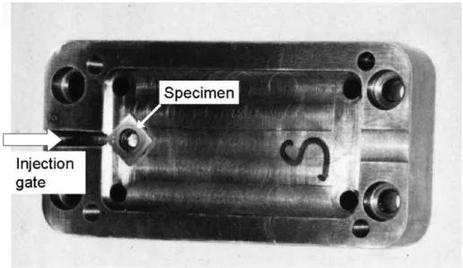
Fig. 2. Test injection mould.
Fig. 1. Test specimen and polymer flow.
shots, respectively. The tests were interrupted at intervals for study of the worn specimen surfaces.
2.2. Mould cavities and insert pins
The test pin geometry was a rectangular head on a cylin-drical pin, Fig. 1, where the side surfaces of the head were placed in the polymer resin flow. The pins were placed in the mould cavity with one corner of the head facing the injection gate, Fig. 2. The specimen corner in the injection flow is hereafter called the leading edge. The side surfaces of the head were ground and carefully polished to a mirror shining surface. The leading edge and the adjacent sides of the head were studied for wear damage in a scanning electron microscope at different numbers of injection shots. During one injection cycle, the test surfaces are submitted to different solicitations. The polymer flow collides with the pin in the leading edge area, where the polymer flow di-vides into two streams along the head side surfaces, Fig. 1. Maximum geometric attack angle of the polymer flow to the side surface at the leading edge is 45◦.
Table 3
Physical properties of the polymer Density (g/cm3) Young’s
modulus (MPa)
Hardness (MPa) Thermal conductivity (W/m◦C)
Thermal coefficient (◦C)−1
1.52 10000 145 0.22 2× 10⁻⁵
2.3. Materials
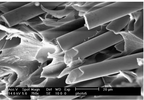
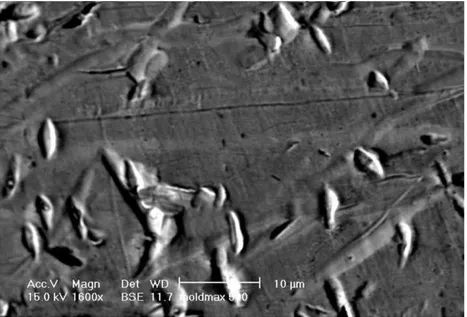
The polymer Lexan 341R-739 polycarbonate resin was used, and which is reinforced with 40 wt.% of short glass fibres, see Table 3 for properties. The glass fibres and pos-sibly the flame retarding agents will increase the mould surface degradations through abrasive and chemical wear, respectively. The glass fibres have a diameter of 10–15 !m and a length of 50–300 !m, and the fibres have very sharp ends, Fig. 3.
The tool materials in the test pins are three tool steel grades and one copper–base alloy, see Table 4. IMPAX Supreme, equivalent to AISI P20, is an ingot cast low alloyed martensitic pre-hardened mould steel, STAVAX ESR, equiv-alent to AISI 420, is a high alloy martensitic stainless mould steel with a dispersion of smaller primary carbides (carbides
Fig. 3. SEM image of the glass fibres.
Table 4
Chemical composition of tool materials (wt.%)
Tool grade C Si Mn Cr Mo V Ni Sn Cu
IMPAX Supreme 0.37 0.3 1.4 2.0 0.2 1.0
STAVAX ESR 0.38 0.9 0.5 13.6 0.3
ELMAX 1.7 0.4 0.3 18.0 1.0 3.0
MOLDMAX 9.0 6.0 85.0
of chromium or vanadium) but in a low quantity. ELMAX is a high alloyed powder metallurgy stainless mould steel with larger primary carbides (with hardness of about 1700 HV, containing chromium, vanadium and molybdenum). MOLD-MAX is an ingot cast high strength copper mould alloy. Measured hardness are 370, 547, 615 and 374 HV for IM-PAX, STAVAX, ELMAX and MOLDMAX, respectively.
3. Wear results
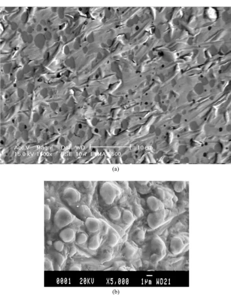
The wear mechanism study revealed mainly abrasive wear by hard particle abrasion through micro cutting and micro ploughing and wear by solid particle impact through plastic deformation and removal of material. The glass fibre endings seem to either leave traces of intendations
when the polymer is flowing over the surface, or leaving impact markings when hitting the surface. The proportions and amount of the different mechanisms depend on (i) the location in the mould, i.e. flow variables from mould geo-metry resulting in different wear zones, (ii) the injection conditions and (iii) on the response of the mould material.
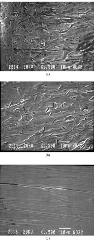
Fig. 4. IMPAX, jetting injection conditions 4500 shots, SEM image: (a) impact erosion close the leading edge; (b) abrasive wear 250 !m behind the leading edge; (c) abrasive wear 2 mm behind the leading edge.
3.1. Different wear zones
Wear was found to vary over the specimen surface, show-ing different wear mechanisms dependshow-ing on the distance from the leading edge. We can roughly distinguish two wear zones, one close to the leading edge and the other further away from it. The leading edge receives the polymer flow straight from the feeder gate, and the reinforcing fibres are projected with their ends first on the leading edge with great force. In this zone a solid particle impact erosion wear mechanism is dominating. In the impact erosion zone we observe plastic deformation and erosion of the matrix. Ev-ident amount of plastic deformation and erosion is present even for a low shot numbers, and increases with the number of shots. Fig. 4a shows impact markings at the leading edge of an IMPAX specimen, which is full of ductile intendation marks.
Further along, just near the leading edge, sliding between the hard fibres and the tool surface appears as the polymer flows increasingly parallel to the specimen surface, and here the surface exhibits sliding grooves from the glass fibres, see Fig. 4b and c. These grooves are abrasive wear of the types micro ploughing and micro cutting.
3.2. Different injection conditions
Jetting injection conditions will bring about high velo-cities of the fibres hitting the leading edge in a straight forward fashion with fibre endings impacting the specimen. The high pressure will also through the higher shear strain rate force the fibres harder against the surface in the poly-mer glide zone. This is evident as the polypoly-mer glide zone 2 mm behind the leading edge for an IMPAX specimen, Fig. 4c, is observed.
Like what is specified in Table 2, tests were also carried out with normal injection conditions, and the leading edge as well as the side surface of each pin was observed. Nor-mal injection conditions will entail impact markings on the
Fig. 5. IMPAX, SEM image of impact markings in normal injection conditions, 110 shots close to the leading edge.
Fig. 6. IMPAX, jetting injection conditions 500 shots, SEM image close to the leading edge.
specimen surface, but not as large and frequent as in the jet-ting condition, Fig. 5. The same is valid for the polymer glide zone, micro cutting occurs but not as deep and frequent.
3.3. Different test materials
The wear response to the injected reinforced polymer is depending on tool material properties. Primarily impact and abrasive wear dominates the wear damage occurring in the test, as shown by Figs. 6–10. Plastic deformation was observed on all the specimens, which was more or less important according to the specimen material. IMPAX and MOLDMAX present wider grooves of plastic deforma-tion. The scratches of ejection, transverse to the injection
Fig. 7. STAVAX, jetting injection conditions 500 shots, SEM image close to the leading edge.
traces, observed at the back of the specimens were also more marked for these two materials. It is also noted that STAVAX specimens presented grooves of abrasion at the leading edge more that are deeper than for ELMAX specimens.
IMPAX, Fig. 6, is shown to behave in a fairly ductile man-ner, where impact markings and the abrasive components of cutting and ploughing are large as compared to the harder materials in the test. There is a higher amount of ploughing and the grooves are long and deep. The impact erosion wear at the leading edge is greater than with the other materials. STAVAX, Fig. 7, shows plastic deformation of the leading edge with impacts but a lesser ability to plastically deform than IMPAX, exhibiting less ploughing in favour to cutting and the wear grooves are not as long. The surface close to
Fig. 8. ELMAX, jetting injection conditions, SEM image close to the leading edge: (a) 500 shots; (b) 4500 shots.
Fig. 10. MOLDMAX, jetting injection conditions 500 shots, SEM image close to the leading edge.
the leading edge is characterised by parallel polymer flow with grooves of micro cutting and ploughing.
ELMAX, Fig. 8a, is even less prone to plastic defor-mation than STAVAX, but in ELMAX the larger primary carbides play an important role. The carbides show no evident deformation and markings or abrasive scratches are not seen on them in these SEM-photos. They also tend to end the abrasive grooves, which are shorter and fewer. With continued number of injection cycles the effect of carbides is more evident. After 4500 shots with jetting injection conditions there was a severe impact erosion effect close to the leading edge, Fig. 8b. The matrix is eroded while the harder carbides are left protruding out of the surface. When injection conditions were changed to normal, the impact erosion becomes less important in favour to cutting and ploughing mechanisms, Fig. 9.
MOLDMAX is similar to IMPAX in appearance, but is not deformed to the same extent. It seems as if the abra-sive grooves are shorter, but otherwise well formed with ploughing and cutting traces, see Fig. 10. Also similar to the IMPAX specimens, there is impact erosion of the leading edge and abrasion of the side surfaces, but the mechanism of erosion is more important.
4. Discussion
4.1. Model proposal
The most important wear mechanism of moulds in a nor-mal injection conditions are shown by the presented results to be hard particle abrasion through cutting and ploughing due to fibre endings tracing wear scars in the mould surface. The shear stresses transferred from the polymer melt forces the fibre endings to intend the surface as they are gliding
past. Therefore, an attempt to model this is made and dis-cussed below, in order to clarify the influence of the different parameters.
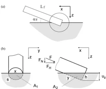
Predicting the level of stress that the fibre is subjected to by the polymer flow as it is in contact with the surface is very difficult. However, we can make an estimate of the level of stress acting on the fibre from the polymer melt, by considering the stresses acting on a fibre at stand still in a polymer flow, see Figs. 11–12. The frictional forces will allow the transfer of stress to the fibre and, hence, the fibre stress will increase with fibre length. With constant friction, equilibrium requires that
π rf2 ! σf+ dσf dx dx " − πrf2σf+ 2πrfτdx= 0 or dσf dx = − 2τ rf (1) Thus, fibre stress, σf, will increase linearly from the ends
of the fibre, through the frictional stress τ acting at the fibre interface. Then, for a glass fibre that is aligned in the direction of the flow ˙γ , the frictional stress τ at the interface can be estimated by the capillary melt viscosity η as
τ = η ˙γ (2)
From integrating over the fibre length together with Eq. (2), maximum fibre stress located at the fibre end can be calcu-lated as
σfmax =
2η˙γ lf
rf
(3) Hence, the magnitude of the force F acting at the fibre end necessary to support an aligned fibre subjected to a flow can be written as
F = σfmaxπ r 2
Fig. 11. Model proposal and definitions of variables.
Fig. 12. Equilibrium conditions.
where for reasonable small inclination angles the normal component FN is estimated from
FN ∼= F sin(αf) (5)
where αf denotes the inclination angle.
From the micrographs in Figs. 4 and 10 it is evident that the polymer flow results in imprints of glass fibres into the metal surface. Resistance to intendation is measured as hard-ness, where from a known hardness and a known imprint contact area the force necessary to cause that imprint FN,
can be estimated from
FN ∼= HA (6)
where A denotes the contact area and H the hardness according to Vickers.
The actual imprint contact area for an inclined glass fibre as it is pressed into the surface are the sum of the area at the fibre end, A1, and the area of the fibre surface, A2, see
Fig. 11. When assuming the deformation of the glass fibre to be negligible the fibre end area A1is calculated from fibre
diameter r, fibre inclination angles αf, and imprint depth
uz. The fibre surface contact area A2is estimated from the
triangle given by the length of fibre in contact y and the length of arc s. The total imprint area A is then calculated as the sum of the two areas:
A= A1+ A2 (7)
As uz and αf are considered as variables of imprint force,
where FN can be written as
FN= FN(A)= FN(A(uz, αf))= FN(uz, αf) and, hence,
FN= G(uz, αf) (8)
With imprint force FNas a function, G(uz, αf) a set of
incli-nation angles, αf= αf;iG(uz, αf;i)defines fi(uz) such that
G(uz, αf)= G(uz)= fi(uz) and uz;i= fi−1(FN) (9)
Thus, for a set inclination angle αf;i, uz;i= g( ˙γ ) since
uz;i= fi−1(FN)= fi−1(FN(˙γ , αf)) and with set αf;i
fi−1(FN(˙γ , αf;i))= gi(˙γ ) = uz;i(˙γ ) (10)
The calculations are performed for different αf;i, and where
uz(˙γ , αf)is known. The imprint width wyis calculated from
imprint depth uz by geometry.
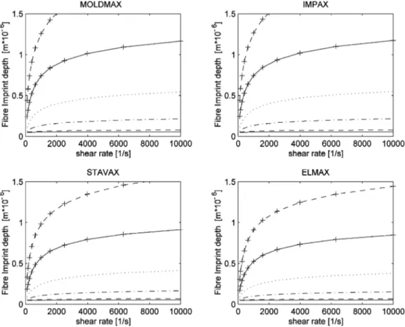
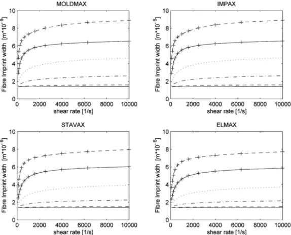
The calculations are performed on a fibre length of 300 !m and a polymer melt temperature of 300◦C, using melt flow data of shear rate ˙γ of Lexan 3414, a new grade which is equivalent to the old grade Lexan 341R-739, from GE Plastic Co. The results are presented in Figs. 13 and 14, with imprint depth and width as a function of polymer shear flow rate and fibre inclination angle.
4.2. Model discussion and influence of injection conditions and polymer type influence
Abrasive wear of the metal surface is directly related to the imprint depth and width. The width of an abrasive scratch can be estimated by the imprint width, and thus, the wear rate is expected to follow the development of imprint depth.
The injection conditions and polymer type is represented in the proposed model by shear rate and fibre dimensions. From Eq. (3) it follows that increasing fibre length leads to higher force at the fibre ending, and thus, larger imprints, whereas fibre diameter is not directly of such large signifi-cance. Increasing shear flow rate of the polymer will add to the transferred frictional stress on the fibre and increase the imprint size. Flow data used here are melt data properties, whereas during injection of the polymer into the mould the thermal exchanges with the mould surface may lead to a rapid increase in viscosity. This will induce a higher fric-tional shear stress on the fibre, and thus, increasing imprint size and depth in the die surface.
In Fig. 13 the calculated imprint depth is presented for different inclination angles. As one of the mould materials is considered we note that for a given inclination angle the imprint depth possible is dependent on shear flow rate. The imprint depth increases rapidly with shear rate at low shear rates and levels of at high shear rates. In principle similar behaviour is observed for the imprint width, Fig. 14. Two mechanisms both causing the imprint depth and imprint width to level off at high shear rates can be identified. First, the polymer melt exhibits a significant decrease in viscosity at high shear rates, and secondly although a higher shear
Fig. 13. Model data, imprint depth as a function of shear rate.
stress results in a higher imprint force the imprint area in-creases rapidly as the fibre is pressed into the material. Con-sistently, the resulting depth exhibits only a slight increase. Mennig [4] presents results were the wear rate is measured for a glass fibre filled PA 66 at varying shear rates. The wear rate was shown to increase with shear rate and to bend of at higher shear rates in a similar fashion as the presented imprint depths and widths in Figs. 13 and 14.
The dependence on inclination angle for imprint width and depth is strong, as seen from Fig. 13. From simulation on fibre orientation during shear flow [5–7] and measurement [8] the fibre is expected to be orientated in the direction of flow, and the inclination angle αf, hence, expected to be
small. For small inclination angles we then expect the wear to be comparatively small.
4.3. Wear zones
In injection moulding dies there are normally a variety of polymer and die wall contact and interfacial conditions, e.g. opening or narrowing die space and wall curvatures, which will change the polymer flow conditions. In the presented test results this would be corresponding to the different wear zones at the leading edge and the polymer glide zones. Clearly, there is a solid particle impingement erosion mechanism at the leading edge where there are high fibre inclination angles, and gliding abrasive wear at
the polymer glide zones where there are lower inclination angles.
Then as simulations [9,10] and observations [8,11] of fibre orientation in polymer flow in more complex mould cavities indicates, higher inclination angles αfare expected
close to changes in mould channel direction and dimen-sion. Nishimura et al. [11] investigated fibre orientation in a branching channel and found that the fibre inclination close to the mould surface to varied with distance from the inlet. They reported an average inclination angle close to the inlet to be 30◦whereas after 60 mm along the channel the fibres were aligned with the flow. They concluded that although a wide range of fibre orientations were found close to the inlet fibres tend to align along the flow direction in the down stream region. The tendency became clearer with an increasing fibre length close to the walls. Kunji and Nakmura [9] studied fibre orientation in a circulating flow and concluded that although all fibres align along the streamlines for large fibre aspect ratio the preferred angle are oblique to the streamlines for short fibres. Further Lee et al. [10] predicted what would result in high inclination angles towards the metal surface as they studied the filling of complex shape moulds. The high inclination angles were found at corners in the mould. In a Diploma work [12] the wear of a tool in use at Volvo Car Corporation was studied and noticeable wear of the tool was found at radiuses and corners where higher inclination angles were foreseen.
Fig. 14. Model data, imprint width as a function of shear rate.
From our calculations on imprints of glass fibres the wear is expected to be comparatively large where the inclination angle is high. Then, as we consider the results of the wear test procedure for a normal injection condition we expect the imprints and, hence, the grooves observed to be deeper and broader at the leading edge where the fibre inclination angle is expected to be large. As we continue with the flow and leave the region at the leading edge, the imprint depth and width of the groove is expected to decrease. This for two reasons, first the fibre inclination angle is expected to de-crease as the fibre align with the direction of flow. Secondly, the flow rate has reduced since the cavity size increased.
4.4. Material response
The proposed model for polymer flow fibre indentation in a die surface takes into consideration the yield limit of the die material, leading to the diagrams of imprint depth and width, Figs. 13 and 14. Thus, imprint size will decrease with increasing yield limit, or hardness, of the die material, and the wear will decrease in the same proportions. Comparing actual imprint width of a wear trace from the test surfaces, Figs. 4–8, it is seen that model predictions are of the same order. However, it is also apparent that the mechanism of the fully martensitic IMPAX grade is not similar to the car-bide rich ELMAX grade. The influence of the hard carcar-bide phase in impact erosion is evident when comparing Fig. 4a
and 8b, where in the latter case the softer martensite matrix is predominantly eroded leaving the carbides protruding in the surface. On the other hand, examples of abrasive wear of ELMAX under normal injection conditions, seen in Fig. 9, where micro ploughing and micro cutting occurs. Here, the wear seems more homogeneously distributed over the softer martensite and harder carbide phases. For hard phase containing materials rules of mixtures may be used to model wear [13]. In the ELMAX case it may then be argued that the wear behaviour is not predominantly determined by the harder carbide phase but the softer martensite phase if wear is carried homogeneously by the different phases. These leaves a potential for increasing the ELMAX resistance to abrasive wears by optimising martensite to carbide wear in-teraction, e.g. by optimising hardness and size distribution of the phases. Also, it was observed from the appearance of wear markings that the copper base alloy MOLDMAX did show higher resistance to micro ploughing and micro cutting than IMPAX of the same yield limit. This may be attributed to the difference in deformation response, where the copper base alloy has higher degree of deformation hardening characteristic. It has been shown that the ability to form grooves by a sliding indenter was dependant on the materials strain hardening properties, where increasing strain hardening would have the same effect as reducing the attack angle of the indenter [14,15]. The ability of the inden-ter to displace mainden-terial would then decrease, where micro
ploughing would occur less in favour to micro cutting, and the grooves would be less deep.
5. Conclusions
The morphology and the density of glass fibres can ex-plain the very abrasive capacity of the polymer. The fibres behave like multi-indenters carried by a fluid. Taking into account the impact erosion feature on the leading edge pin sample, will let us suppose an initial impact property of the glass fibres which is significant. The power emit-ted at the contact entrance is important. If translaemit-ted to terms of pressure× speed, the power per surface unit is equal to 700 W/mm2under jetting injection conditions and 30 W/mm2under normal plastic injections conditions. Vari-ations in the polymer flow orientation arising from corners and shape variations in the mould cause fibre orientations in relation to the die surface to alter. In the model calculations imprint depth and width are strongly dependent on the fibre inclination angle, where high angles result in larger imprint depths, and thus, cause severe wear.
The jetting injection condition makes it possible to per-form wear testing with shorter test time. The wear mech-anisms are similar to those in normal injection conditions, even though the impact erosion mechanism is more impor-tant than for the normal case. Testing and ranking of tool materials is possible to perform this by evaluating wear separately at the leading edge and in the polymer glide zone. Continued verification and development of the wear model will make it possible to predict die wear of a hard phase reinforced polymer injection.
Acknowledgements
The financial support by the Uddeholm Research Founda-tion and work carried out by C. Johansson and M. Jornelid is gratefully acknowledged.
References
[1] B. Gehricke, I. Schruff, Trends in plastic mould steel applications, in: F. Jeglitsch, R. Ebner, H., Leitner (Eds.), Proceeding of the Fifth International Conference on Tooling, Montanuniversitat Leoben, Leoben, Austria, 1999, p. 775.
[2] M. Heinze, Wear resistance of hard coatings in plastics processing, Surf. Coat. Technol. 105 (1998) 38.
[3] E.J. Bienk, N.J. Mikkelsen, Application of advanced surface treatment technologies in the modern plastics moulding industry, Wear 207 (1997) 6–9.
[4] G. Mennig, Wear in Plastics Processing: How to Understand, Protect and Avoid? Carl Hanser, Munich, 1995, p. 452.
[5] M. Vincent, E. Devilers, J.F. Agassant, Fibre orientation calculation in injection moulding of reinforced thermoplastics, J. Non-Newtonian Fluid Mech. 73 (1997) 317–326.
[6] S.T. Chung, T.H. Kwon, Numerical simulation of finer orientation in injection molding of short fibre reinforced thermoplastics, Polym. Eng. Sci. 35 (1995) 604–618.
[7] S.H. Chang, J.R. Hwang, J.L. Doong, Optimisation of the injection moulding process of short glass fibre reinforced polycarbonate composites using grey relational analysis, J. Mater. Process. Technol. 97 (2000) 186–193.
[8] J.J. McGrath, J.M. Wille, Determination of 3D fibre orientation distribution in thermoplastic injection molding, Composites Sci. Technol. 53 (1995) 133–143.
[9] C. Kunji, K. Nakamura, Numerical solution of fibre suspension flow through a complex channel, J. Non-Newtonian Fluid Mech. 78 (1998) 167–185.
[10] S.C. Lee, D.Y. Yang, J. Ko, J.R. Youn, Effect of compressibility on flow field and fibre orientation during the filling stage of injection molding, J. Mater. Process. Technol. 70 (1997) 83–92.
[11] T. Nishimura, K. Yasuda, K. Nakamura, Orientation behaviour of fibres in suspension flow through a branching channel, J. Non-Newtonian Fluid Mech. 73 (1997) 279–288.
[12] C. Johansson, M. Jörnelid, A Study of Wear of Tool for Plastic Processing, Diploma work, Department of Engineering Sciences Physics and Mathematics, Karlstad University, 1999.
[13] K.H. Zum Gahr, Wear by hard particles, Tribol. Int. 31 (1998) 587–596.
[14] J.A. Williams, Wear modelling: analytical, computational and mapping — a continuum mechanics approach, Wear 225–229 (1999) 1–17.
[15] J.A. Williams, Y. Xie, The generation of wear surfaces through the interaction of parallel grooves, Wear 155 (1992) 363–379.