COMPARISON OF DAMAGE MODELS IN THE VIRTUAL
TESTING OF COMPOSITES
Michaël Bruyneel, Jean-Pierre Delsemme, Philippe Jetteur LMS Samtech, A Siemens business
Liège Science Park Angleur 4031, Belgium
ABSTRACT
In this paper, the models for the progressive damage modeling of composites that are available in the SAMCEF finite element code are described. The new non local approach, coupling inter and intra-laminar damages is also described. Since they include many parameters, a procedure for the parameter identification is discussed. A comparison of the solution obtained with the classical damage models and the new advanced formulation is conducted.
1.
INTRODUCTION
Recent results obtained in the modeling of inter and intra-laminar damages with the SAMCEF finite element code are presented. A specific model available in SAMCEF can be used to study the progressive damage inside the ply, accounting for fibers breaking, matrix cracking and fiber-matrix de-cohesion. On the other hand, delamination can also be studied with the cohesive elements approach. These models are based on the continuum damage mechanics, and damage variables impacting the stiffness of the ply or of the interface are associated to the different failure modes. A new non local model has been implemented recently, based on the work of Cachan [1]. This model couples the two kinds of damages, meaning that the transverse micro-cracking appearing inside the plies will influence the initiation of delamination at the interface of the plies. With this new model, delamination occurs earlier in terms load level, what is closer to what is observed in the physical tests.
In this paper, this new non local model is described. Since it includes many parameters, a procedure for the parameter identification is discussed. A comparison of the solution obtained with the classical damage models and the new advanced formulation is then conducted.
2.
DAMAGE MODELLING WITH SAMCEF
2.1 Intra-laminar damage modeling
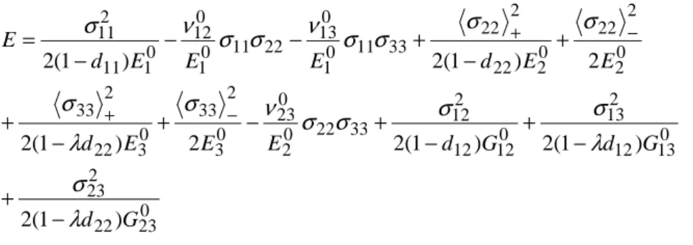
The damage model for an unidirectional ply is based on the work done at Cachan and presented in [1,2]. It is extended here to the general 3D case in (1) and is expressed in terms of the stresses. Three damage variables are taken into account. The first one, d11, manages the damage in the
fibre direction; the second one, d22, collects the damage in the transverse direction (occurring
only in traction), while d12 can handle the damage in the shear direction, reflecting the
de-cohesion between the fibres and the matrix. When the plane stress assumption is not done, the damage can also occur in direction 3. The parameter λ, whose value is equal to 0 or 1, is then introduced.
0 23 22 2 23 0 13 12 2 13 0 12 12 2 12 33 22 0 2 0 23 0 3 2 33 0 3 22 2 33 0 2 2 22 0 2 22 2 22 33 11 0 1 0 13 22 11 0 1 0 12 0 1 11 2 11 ) 1 ( 2 ) 1 ( 2 ) 1 ( 2 2 ) 1 ( 2 2 ) 1 ( 2 ) 1 ( 2 G d G d G d E E E d E E d E E E d E λ σ λ σ σ σ σ ν σ λ σ σ σ σ σ ν σ σ ν σ − + − + − + − + − + + − + − − − = − + − + (1)
As the strains can be determined by the derivative of the potential (1) with respect to the stresses, the thermodynamic forces Yi are computed as the derivatives of the potential with respect to the damage variables di. The damages increase as the corresponding thermodynamic force increases, as illustrated in Figure 1, where Y = Y12 + b2Y22. It is also noted that d22 = b3d12. As soon as either d12 or d22 is equal to 1, then d22 or d12, respectively, is set to 1: once the ply is broken in the transverse direction because of too many cracks in the matrix, the resistance to shear vanishes; the opposite is also true. Figure 1 shows the different behaviors that can be represented by the current model. Non linearities can be taken into account in traction and compression in the fiber direction. The fibers have a fragile behavior, while the matrix is more ductile. Permanent deformation can also be taken into account in the matrix.
Figure 1. Behaviors represented by the available model
For modeling the damage, several parameters then have to be identified: Y012, Ys12, the expression of the non-linear part of d12=d12(√Y), Ys22, Y011 (in traction and compression), b2 and b3. Besides the damage associated to the failure of the ply, permanent deformation is also
observed, when the matrix is loaded (Figure 2). The equations are given in (2), and the parameters to identify are R0, β, γ and a. Note that the effective stresses are used in the plasticity
criterion. 0 ) ( ) ~ ~ ( ) ~ ~ ( ~ ) , ~ ( p = 122 + 132 + 232 +a2 222 + 332 −R0−R p ≤ f σ σ λ σ σ σ σ γ βp R p R( )= 0+ (2)
Figure 2. Permanent deformation in the matrix of a [45/-45]2s laminate
As reported in [1], all these parameters, as well as the elastic constants, can be identified based on the tests results on three different laminates, that are coupons with 0/90, 45/-45 and 67.5/-67.5 stacking sequences. The test on the 0/90 allows to determine the properties in the fibre direction; the tests on the 45/-45 are used to identify the shear parameters, as well as the parameters for plasticity (except the parameter called a); finally, the tests results on the 67.5/-67.5 can provide the coupling coefficients.
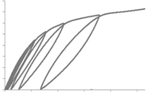
The identification of the parameters entering the model can be done based on a set of simple tests at the coupon level. Typically, tests in traction and compression on a laminate including 0° and 90° plies are conducted to determine the behavior in the direction of the fibers. For the matrix properties, tests on laminates including 45° and -45° plies are conducted. The damage properties are determined under loading and unloading conditions (Figure 3). Finally, the coupling between shear and transverse damage is identified with tests on 67.5/-67.5 stacking sequences.
2.2 Inter-laminar damage modeling
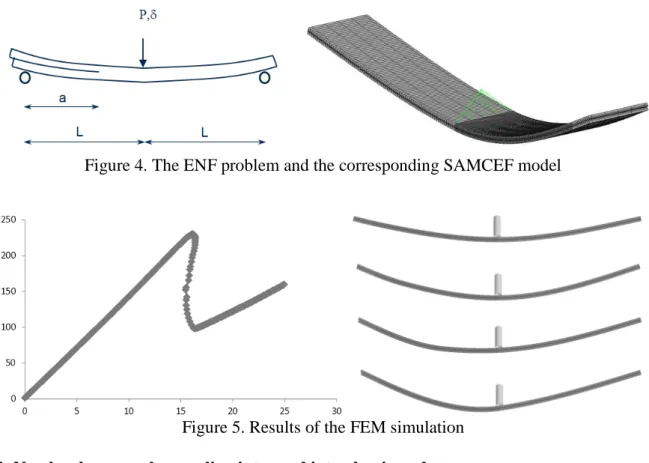
Delamination is modelled in SAMCEF with the cohesive elements approach developed by Cachan, based on the work described in [3-5]. The implementation was described in [3-6], and is therefore not reported here in details. The cohesive elements approach has been used mainly for the study of stable crack propagation, to simulate either for DCB, ENF or MMB tests. Here, as an illustration of the SAMCEF capabilities, the unstable propagation on an ENF is presented (Figure 4). The initial crack length is such that an unstable path will appear during the crack propagation, what will result in a snap-back in the reaction/displacement equilibrium curve. This unstable path is captured thanks to a continuation approach in the solution of the non-linear equations; in this case the Riks method is used. Figure 5 shows the equilibrium path and the deformation of the ENF over time. It is clear that the crack propagates quite suddenly. This acceleration in the crack propagation leads to a sudden change in the geometry of the specimen. At that time, the snap-back occurs.
Figure 4. The ENF problem and the corresponding SAMCEF model
Figure 5. Results of the FEM simulation 2.3 Non local approach: coupling inter and intra-laminar damages
Based on the work done at Cachan and described in [7], a non-local approach has been implemented in SAMCEF. In this approach, the transverse cracking in the matrix will influence the resistance of the interface, and will therefore initiate the delamination (Figure 6).
On one side, we have the diffuse damage, which is related to the evolution of the damage before the limiting value Ys12 and Ys22 are reached. On the other side, transverse micro-cracking also evolves through the ply thickness. Damages d22, d12 and d23are associated to the
micro-cracking density ρ (3). d23 depends on the damage d22 and on the Poisson coefficient ν23. The stiffnesses are now degraded according to:
) 1 )( 1 ( 22 22 0 2 2 E d d E = − − ) 1 )( 1 ( 12 12 0 12 12 G d d G = − − ) 1 )( 1 ( 23 23 0 22 23 G d d G = − −
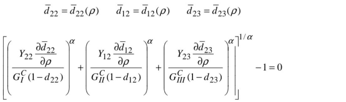
The value of ρ is obtained by solving equation (4).
) ( 22 22 d ρ d = d12 =d12(ρ) d23=d23(ρ) (3) 0 1 ) 1 ( ) 1 ( ) 1 ( / 1 23 23 23 12 12 12 22 22 22 = − − ∂ ∂ + − ∂ ∂ + − ∂ ∂ α α α α ρ ρ ρ d G d Y d G d Y d G d Y C III C II C I (4)
Moreover, the value of the mean micro-cracking density ρ influences the strength of the interface in modes II and III, as expressed by (5) and (6). The damage dI in the opening mode is obtained based on the corresponding thermodynamic force as in the uncoupled inter-laminar approach. For a micro-cracking density larger than a threshold ρs, the damage in the interface in modes II and III takes the value of dI.
If ρ<ρs: − + = 2 sin 2 ) 1 ( I iρ 2 θ I II d d a d and − + = 2 cos 2 ) 1 ( I iρ 2 θ I III d d a d (5) If ρ≥ρs: dII =dI =1 and dIII =dI =1 (6)
In practice , a delay effect avoids the numerical instabilities.
2.4 Non local approach: avoid local damages in the ply
The problem of damage localization is well known in the continuum damage mechanics approach, which is used here. In order to avoid this local effect, a delay in the occurrence of the damage can be used. Another solution is to use a non-local approach; in which some additional degrees of freedom are the non-local thermodynamic forces that must satisfy additional sets of equations in such a way that the local values are smoothed over a domain.
3.
RESULTS
3.1 Static indentation
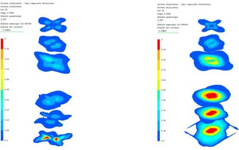
The static indentation of a composite plates is considered. In Figure 6, the value of the damage at the interface of the plies when the uncoupled approach is used is given on the left. On the right, the damage values for delamination when the coupling between inter and intra-laminar models is taken into account. As expected, when the coupled model is used, the value of the inter-laminar damage is larger.
Figure 7. The static indentation problem and the SAMCEF model
3.2 Plate with a hole
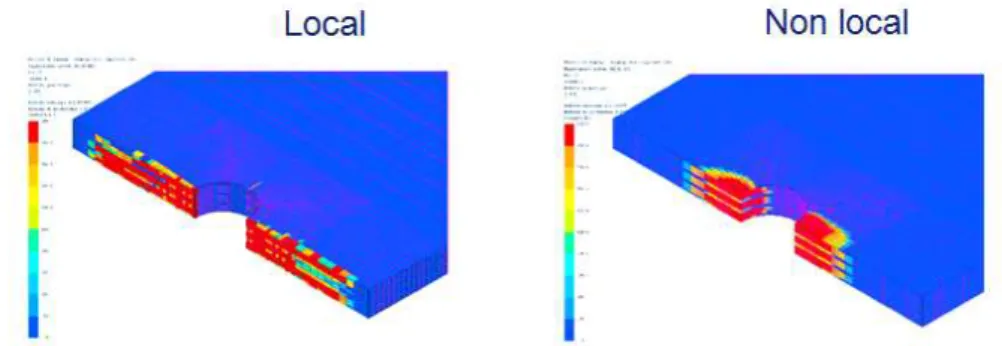
We consider here a plate with a hole. We compare the solution obtained with the local and non local approaches. Inter and intra-laminar damages are considered in the model. Here, the non local behavior is defined inside the ply, but only along the fiber direction. In Figure 9, it is seen that when the local approach is used, strips of high damage values appear. When the non local approach is selected, the fibers breaking is better defined around the hole. The benefit of using the non local approach is also illustrated in Figure 10. For the result of curve 1, the local damage insid the ply is considered. The computation stops before reaching the maximum load. For curve 3, the non local approach inside the ply is used. For curve 2, delamination is also taken into account.
Figure 9. Results for the plate with the hole
Figure 10. results for the plate with the hole
4.
CONCLUSIONS
In this paper, the damage models available in SAMCEF were recalled, and the parameters to identify were listed. A new non local model was described. This model makes a link between inter and intra-laminar damages. Application illustrate the accuracy of the models, when they are used in a coupled and uncoupled way.
5.
REFERENCES
1. Ladeveze P., and Le Dantec S. (1992). "Damage modeling of the elementary ply for laminated composites", Composites Science and Technology, 43, 1992.
2. Ladevèze P. and Lubineau G. (2001). "On a damage mesomodel for laminates : micro-meso relationships, possibilities and limits". Composites Science and Technology, 61, pp. 2149– 2158.
3. Allix O. and Ladevèze P.(1992). "Interlaminar interface modelling for the prediction of laminate delamination", Composite Structures, 22:235-242.
4. Allix O., Lévêque D. and Perret L. (1998). "Interlaminar interface model identification and forecast of delamination in composite laminates". Comp. Sci. Techn. 56 :671-678.
5. Ladevèze, P. et al. (1198). "A Computational Method for damage Intensity Prediction in a Laminated Composite Structure", Computational mechanics—New Trends and Applications In: Idelsohn, S., Oñate E., and Dvorkin E., (eds.) CIMNE, Barcelona, Spain (1998).
6. Brauner C., Delsemme J.P. Jetteur Ph., Bruyneel M., and Kuhlmann G. (2009). "Non linear failure analysis of a reinforced composite curved beam with delamination and ply degradation", NAFEMS World Congress”, 16-19 June 2009, Crete, Greece.
7. Bruyneel M., Delsemme J.P., Jetteur P. and Remouchamps (2010). "SAMCEF for composites : advanced numerical methods for analysis and optimisation", NAFEMS Seminar "Simulating Composite Materials and Structures,2nd – 3rd February 2010, Esbjerg, Denmark. 8. Bruyneel M., Delsemme J.P., Jetteur Ph. and Mertens T. (2011). "Recent results in damage
modelling of composites", NAFEMS World Congress, May 23-26, 2011, Boston, USA. 9. Bruyneel M., Delsemme J.P., Jetteur P., Germain F. (2009). "Modeling inter-laminar failure
in composite structures: illustration on an industrial case study", Applied Composite Materials, 16(3), 149-162.
10. Abisset E. (2012). "Un mésomodèle d’endommagement des composites stratifiés pour le virtual testing: identification et validation", PhD Thesis, ENS Cachan, France.
11. Lubineau G. and Ladeveze P. (2008). "Construction of a micromechanics-based intralaminar model and illustrations in Abaqus standard", Computational Materials Science, 43(1), pp. 137-145.