Numerical analysis and optimization of a fin system
for the thermal control of a Compound Solar Receiver
(CPC)
R. Djarallah,
1 Department of Physics, Faculty of Science, University of Batna1, LPEA, 2University professor of Physics in El-Oued University
Algeria
djarallah-rachida@univ-eloued.dz
Abstract - The work presented consists of studying the flow
of a fluid in a Composite Parabolic Concentrator (CPC) coupled with a solar receiver at the head of a solar power plant in a laminar and turbulent regime under the effect of the heat transfer phenomenon: natural convection, conduction and radiation.
In our study, we have a CPC in the form of a truncated cone and circular fins of trapezoidal shape, it is coupled by a solar receiver composed of two glued truncated cones. The number of fins is set to be (one, three, seven and thirteen).
This work aims to find solutions to reduce the wall temperatures of CPC (Aluminum) to avoid deterioration of its material.
This study led us to propose fin configurations whose choice was to choose the case that gives the lowest wall temperature and that it does not affect the configuration of the CPC so as to avoid the congestion of fins on the wall and also the influence on the temperature of working fluid (heat transfer fluid) inside the solar receiver.
The flow of air inside is permanent three-dimensional and viscous, the process is non-adiabatic, the system is subjected to solar radiation, heat exchange is carried out according to the laws of conservation.
To have a better approach on the thermal behavior and a flowing fluid in the compound system and to make the study in three dimensions, one resorted to the software of simulation "FLUENT" which proved itself in the dynamics of the fluids and heat transfers, this simulation allowed us to determine the thermal parameters especially the parietal temperature and the characteristics of the flow.
After our studies, we chose the case 7 fins as the best case for the cooling of the CPC wall.
Finally, the results obtained are very satisfactory comparing our study with other works.
We also studied the influence of some parameter such as CPC wall thickness, Reynolds number, Quartz lens and angle of inclination α.
Keywords- Central Tower., CPC, Solar Receiver, Fins, Laminar and Turbulent flow, Tridimensional flow.
I. INTRODUCTION :
Renewable energies are clean energies, they come from natural elements: the sun, wind, water, the heat of the earth ... etc.
Among their advantages is to fight against the greenhouse effect, notably by reducing the release of carbon dioxide into the atmosphere.
There are different families and types of renewable energies: solar photovoltaic, solar thermal, wind, biomass and geothermal energy.
In our study, we based on one of the solar photovoltaic type that is solar tower plants.
We are interested in understanding the mechanism of a solar tower plant, and mainly its receiver, which is considered one of the pillars of this plant because it operates under high temperature.
In solar tower systems, solar rays are reflected on positioned mirrors in order to focus solar energy on a single point at their head, known as the central solar receiver. After two years of development, planning and construction, the first solar tower plant is to be commissioned in Jülich, Germany; at the end of 2008, the general contractor Kraftanlagen München completed the construction of the experimental solar power station in Jülich, North Rhine-Westphalia (Germany).
The installation was commissioned at the beginning of 2009. It first worked on gas, because the sun did not shine continuously. [1]
In the spring of 2009, it went into normal operation that is to say in the sun. Exploitation test for the next six months has started. The development of the various components and the system as a whole will follow from 2010. It is planned to commercialize this new technology later for installations of 10 to 50 MW which are located in very sunny countries. After fifteen years without a real construction project, the solar thermodynamic sector reappears at the beginning of the 2000s and becomes an alternative more and more considered
for the production of electricity in the countries having a strong direct sunning and an annual solar resource high. The most mature technology is currently cylindro-parabolic technology.
Studies show, however, that tower plants have a greater potential than cylindro-parabolic plants.
In fact, thanks to the high concentrations attainable at the top of the tower, the tower plants make it possible to work at higher temperatures and pressures, thus offering a better conversion efficiency. Despite a majority of commercial parabolic power plants in the world, tower plants are now experiencing a few industrial-scale projects, such as the GEMA SOLAR salt-fired tower plant (Seville).
The GEMA SOLAR plant is today one of the most successful tower plants with a day and night production of 20 MW. [2]
Generally, in our study the solar receiver is associated with a Composite Parabolic Concentrator (CPC), this block (solar receiver and CPC) is subjected to a concentrated solar radiation coming from the field of heliostats which surround the solar tower.
The CPC concentration ratio is relatively low, compared to the dish or hollow concentrators and generates lower temperatures. Researchers have worked on many CPC thermal applications where ease of use is important, and moderate temperatures are sufficient. The use of CPC has also been reported to improve the power generation of photovoltaic plants. [3]
Because of their ability to focus incident solar radiation across a wide acceptance angle, CPCs have been used for their effectiveness as secondary concentrators in combination with other concentrators. As a result, they play a beneficial role in solar tower technologies, which generate very high temperatures (800°C and above). [4], [5]
Due to reducing the wall temperature of the CPC (Aluminum), we have surrounded in our study the latter by fins to avoid the deterioration of their materials which is sensitive to the high temperatures and to compare our results with those found by A Andreozzi et al, 2012. [6]
A. Andreozzi et al, 2012; [6]. Have studied a system that consists of a steel solar receiver coupled to a CPC aluminum finned. The angle of inclination of the system axis above the horizontal is 11 ° (Fig.1). Therefore, the convection between the system walls and the air is not systematically axisymmetric and a three-dimensional model should be implemented. In their work, they studied the influence of the implantation of the fins on the CPC for the parietal thermal control. To avoid material deterioration.
Fig.1. The croquis of the system studied by (Andreozzi et al, 2012); [6].
Fig.2. The wall temperature profiles of the receiver and CPC for different numbers of fins. [6]
The Fig. 2 shows the results of Andreozzi et al ; [6], from the graph, we notice that the parietal temperature of C.P.C.is reduced each time the number of fins increases.
R.Thinda, 2008; [7] worked on a CPC in truncated form, he used it to heat the air. The corresponding thermal efficiency was 10%. The CPC is capable of accepting solar radiation for long periods each day without always following the sun. It also has the advantage of concentrating diffuse radiation, which is not possible by using an imaging collector.
Jing.D et al., 2009; [8] worked on a photo-catalytic solar hydrogen production reactor based on CPC, which it was designed and tested. The concentration ratio of CPC was 4 and increased hydrogen production by an order of magnitude from 25 ml / h to 300 ml / h, the remaining parameters being constant.
R. Adinberg and M. Epstein, 2004; [9] worked in their study on an experimental device specially designed for the study of solar carbo-reduction of ZnO and is located in one of the
experimental levels of a solar tower, 36 m above ground . The solar radiation concentrated by the CPC is absorbed by a cavity solar receiver and transferred to the reactor.
The receiver was manufactured from Alumina-based ceramic fibers and in the form of a box of 350X 205X 305mm internal dimensions.
II. MATERIAL AND METHODS: A. The geometry:
In our case study we chose the same case study with Andreozzi et al, 2012; [6], but with the CPC at the solar receiver input, as the natural case and in order to verify the results we chose to learn the same measurements and parameters of Andreozzi et al ;[6], with some minimal variations.
The geometry is a coupling of a parabolic concentrator compound (Aluminum) with a solar receiver which is formed by two hollow truncated cones, the input diameter of CPC De = 0.6 m and the exit diameter Ds = 0.2 m, while its length L = 1 m, the diameters of the cone 1 are D = 0.2 m, D' = 0.9 m respectively, and L1 = 0.2 m.
Diameters of the cone 2 are D '= 0.9 m, Ds = 0.18 m and L2 = 0.45 m in length.
The angle of inclination of the system axis with the horizontal is 11 degrees. A Quartz lens is located between the CPC and the solar receiver (Fig 3).
Fig.3. Geometry of the CPC and the Solar Receiver.
Four different configurations of trapezoidal circular fins located on the surface of the CPC are studied in order to give the best thermal performances; their locations (in mm) on the CPC are presented in Fig.4:
Case a: 1 fin, with an outer radius of 0.2 m and a thickness of 0. 006 m.
Case b, c and d: 3, 7 and 13 fins, the outer radius of which is 0.35m and thickness 0.006 m.
Fig.4. Graphical presentation of the 4 cases studied and their dimensions (in mm)
B. The mesh:
For choosing the best mesh, we tested a series of mesh types (structured quad and unstructured tri / tetra) and a number of cells on the results. Shows the type of mesh that has been chosen, it is an unstructured mesh of tetrahedral type (the geometry is of type 3D), the geometry studied is very complex.
Fig.5. Unstructured mesh (3D); (a) Mesh of CPC (28346 Nodes) and the solar receiver (23882 Nodes),(b) Mesh with fins and (c) Mesh of the transverse plane.
C. Different modes of heat transfer:
In our case study three mechanisms of heat transfer exist: between the solid material media (wall CPC, Wings and solar
receiver) and fluid (the air in movement): Convective, conductive and radiative transfer (Fig. 6).
Fig.6. Diagram of the different modes of heat transfer (conductive, convective and radiative) governing the studied phenomenon (CPC
+ Solar receiver).
D. The main equations governing the phenomenon:
To simplify the system of equations we have based on the following conditions:
➢ The viscous and Newtonian fluid. ➢ Incompressible and stationary air
➢ The viscous dissipation flow of heat is negligible. ➢ The energy variation due to compressibility is
negligible.
D.1) In laminar regime: ➢ Continuity equation:
𝑑𝑖𝑣 (𝑣⃗) = 0
➢ Motion quantity conservation equation : 𝑣⃗𝑑𝑖𝑣(𝑣⃗) = −1
𝜌𝑔𝑟𝑎𝑑𝑝 + 𝜈∆𝑣⃗ + 𝑔𝑖 ➢ Energy conservation equation:
𝑣⃗𝑑𝑖𝑣(𝑇) = 𝛼∆𝑇 + 1
𝜌𝐶𝑃
D.2) Equation in Turbulent regime:
To see the influence of the velocity of the fluid on the thermal properties of CPC and the fins, that is, to study the case of windy days, we have studied the treatment of the turbulent case by the variation of the Reynolds number at the entrance of the CPC a comparison of the results will be made
to see which of the two laminar or turbulent phenomena gives better parietal cooling.
➢ Continuity equation: 𝜕𝜌
𝜕𝑡+ 𝜕(𝜌𝑈𝑗)
𝜕𝑥𝑗 = 0 (1) ➢ Motion quantity conservation equation :
𝜕(𝜌𝑈𝑖) 𝜕𝑡 + 𝜕(𝜌𝑈𝑖𝑈𝑗) 𝜕𝑥𝑗 = − 𝜕𝑃 𝜕𝑥𝑖+ 𝜕 𝜕𝑥𝑗[𝜇( 𝜕𝑈𝑖 𝜕𝑥𝑗+ 𝜕𝑈𝑗 𝜕𝑥𝑖) − ( 2 3𝛿𝑖𝑗 𝜕𝑈𝑘 𝜕𝑥𝑘) − 𝜌𝑢𝑖𝑢𝑗̅̅̅̅̅] (2)
−𝜌𝑢𝑖𝑢𝑗̅̅̅̅̅: Are the Reynolds constraints, they will be calculated according to each turbulence model (k-ε, k-w, ... etc).
➢ Energy conservation equation: 𝜕(𝜌𝐸) 𝜕𝑡 + 𝜕(𝜌𝑈𝑗𝐸) 𝜕𝑥𝑗 = 𝜕 𝜕𝑥𝑗[𝜆𝑐 𝜕𝑇 𝜕𝑥𝑗+ 𝑈𝑖𝜏𝑖𝑗− 𝜌𝐶𝑣𝑢̅̅̅̅̅] (3) 𝑗𝑇′ Fluent provides the choice of different turbulence models: *The model has a Spalart-Allmaras equation.
*Models with two equations: (k-standard model, Renormalization-group (RNG) k- model Realizable k-, model SST k- ....)
* Models with five Reynolds stress model equations (RSM).In our work we chose the k-standard model.
According to the temperature range of our work which is 300 to 1123 K, the approximation of Boussinesq is not valid. Indeed, in this temperature range, the product of the coefficient of thermal expansion of the air:
𝛽 =1 𝑇=
1
300= 0.003 and for the temperature between the wall of CPC And air, β is in the range of 0.3 to 3.075.
III. RESULTS AND DISCUSSIONS:
In our study we mainly based on the cooling of the wall of the C.P.C., by fins welded on its lateral surface, in this part the results of the three-dimensional computations compared with those obtained by A.Andreozzi et al, 2012.
A. Parietal temperature profile:
Each time, a number of fins are added to the wall of the C.P.C. A comparison of the results is made for these different numbers (1, 3, 7 and 13 fins) with C.P.C. without fins for Re = 600, an ambient air temperature is T = 300k. The results obtained are presented in the following graph:
Fig.7. Parietal temperature of the system for the different number of fins.
We notice from Fig. 7 that each time the number of fins increases the wall temperature of the CPC decreases in the region near the solar receiver as well as the location of the location of the fins. Compared with the finned cases with case 7 fins, we note that the increase in the number of fins has no effect (the decrease in temperature is very small compared to the case 7 fins, a difference of the order of 0.53 therefore the case 7 fins is the best result, It will be chosen to present the majority of the results that follow.
B. Influence of Reynolds number:
Fig.8 gives the parietal temperature profiles for different Reynolds numbers (Re), for CPC with 7 Fins:
Fig.8. Influence of the Reynolds number on the wall temperature of the CPC (case 7 fins).
We note from the graph (Fig. 8) that in the laminar case (Re = 600 and Re = 1500) the decrease of the parietal temperature of CPC is small compared with the turbulent case (Re = 5000.104 and Re = 3.58.105). Thus the turbulence, by its diffusivity favors the cooling of the wall of the CPC.
C. Temperature contours of the wall of the CPC and of the fins:
We present the contours of the static temperature for the various cases 1, 3, 7 and 13 fins in the following Figs. 9A,B and 10:
Case 1 Fin , Re=600
Case 3 Fins, Re=600
Fig.9A. Contours of parietal temperature (a) of the CPC with fins,
(b) wall of the CPC and (c) the fins, cases 1, 3 Re = 600.
Case7 Fins, Re=600
Fig.9B. Contours of parietal temperature (a) of the CPC with fins,
(b) wall of the CPC and (c) the fins, cases 7 fins Re = 600.
Case7 Fins Re=104
Case 13 Fins, Re=600
Fig.10. Contours of the wall temperature (a) of CPC with fins, (b) CPC wall and (c) fins, 7 Fins (Re = 104) and 13 Fins (Re = 600).
According to Fig.9A, B and Fig.10 we see that the wall temperature in the case where turbulent 7 fins, Re = 104 is less than that in the laminar case, Re = 600 (the hot zone is wider in the laminar case that the turbulent cases) and this appears particularly along the wall of the CPC and the vicinity of the lens Quartz.
Also whenever the number of fins increases the wall temperature of the CPC decreases.
D. Contours of the fluid temperature (air):
We present the contours of the static air temperature for the case 7 fins in the laminar case, for a Reynolds number (Re = 600) and in the turbulent case we chose the k-ε model and a turbulent Reynolds (Re = 3.58, 105):
Re= 600
Re= 3, 58 .105
Fig.11.Contours of the fluid temperature (Air) for the case 7 fins (Re = 600 and Re = 3, 58 105).
We note from Fig. 11, Re = 600 that the temperature of the fluid is about 300 k at the entrance to the CPC, and then gradually increases as it approaches the Quartz lens to reach up to 596.77 k. At the solar receiver the fluid temperature (air) gradually increases from the quartz lens (550 k) to the outlet (steel wall) to reach almost 1100 k. While the temperature of the fluid in the case Re = 3.58. 105 from the contours in the CPC decreases more than for the previous laminar case (Re = 600) (especially in the area close to the Quartz lens).
Therefore, we conclude that the temperature of the fluid varies in the same way as the temperature of the walls (due to the phenomenon of convective heat transfer between fluid (air) and solid (wall of the CPC)).
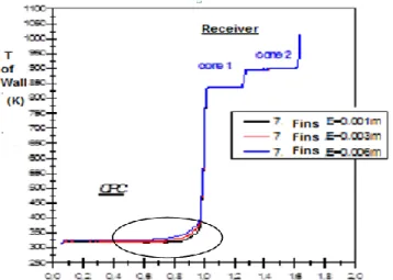
E. Influence of the thickness "E" of the wall of the CPC on the profile of its parietal temperature:
Each time we modify the wall thickness of the CPC is, in order to see its influence on the wall temperature of CPC (Three values were chosen: E = 0.001 m, 0.003 m, 0.006 m) the results obtained are presented on the following graph:
Fig.12. Influence of the wall thickness of the CPC (E) on its parietal temperature (Case 7 fins), (The CPC having a length x = 1m).
We notice from the curve (Fig.12) that each time we decrease the thickness of the wall of the CPC, its temperature decreases. So the thickness is low and favorably, CPC-Air (thermal transfer Convection) and CPC-fins (by Conduction), which allows to cool more the wall of the CPC, whose difference is almost 6.68%.
F. Influence of the angle of inclination (α) of the solar receiver-CPC on the profile of the wall temperature:
For this case we compare the results between the case where the angle of inclination (α = 0 °) and (α = 11 °), the results obtained are presented in the following graph:
Fig. 13. Influence of the inclination angle (α) of the "CPC-receiver" set on the wall temperature of the CPC.
We observe from the graph (Fig. 13) that the wall temperature of the CPC in the case of a receiver inclined by a small angle α = 11 ° is less than the case α = 0 °. A small angle of 11 ° can produce a diffusion of solar radiation, which is necessary for thermal transfer, which causes a good cooling of the wall of the CPC.
G. Influence of the presence of the Quartz lens on the contour of the fluid temperature (Air) and on the profile of the parietal temperature:
Case without Quartz
Case with Quartz
Fig.14. The contours of the fluid temperature case without and with the Quartz lens (cross section, case of one fin).
Fig.15. Influence of the Quartz lens on the temperature of solar receiver and CPC.
By comparing the two cases with and without the Quartz lens, we notice that the temperature of the air in the solar receiver is great in the presence of the quartz lens by-contribution to the case of the absence of the Lens (Fig 14, Fig 15), while the variation in temperature in the CPC is very low.
So we conclude that the Quartz lens has a role to influence the temperature of the fluid (air) downstream of the CPC (in the solar receiver).
VI. CONLUSION:
During this work, we approached the thermal study of a system coupled with a solar receiver at the head of a solar tower, the Composite Parabolic Concentrator (CPC), it is used as a primary receiver. In order to reduce the wall temperature of the latter which can reach 1200k, this temperature can affect the material (Aluminum of wall CPC) and can cause serious deterioration, the idea was to propose adding fins to the wall, then optimize their number.
The comparison with the work done by (Andreozzi et al, 2012) has made the results very satisfying. This study on this system allowed us to apply and better understand the laws encountered during our training in physical quality energy specialty.
The numerical simulation is done by the use of the Fluent code, which allowed us to determine the thermal parameters and the characteristics of the flow.
The finned case was chosen as the best case for cooling the wall of CPC.
The role of the Quartz lens is to further concentrate solar radiation to increase the air temperature downstream of the CPC (in the solar receiver) this allows to produce more electric power than the case without Quartz.
We also conclude that the turbulent case gives good results in comparison with the laminar case.
A small thickness of the CPC allows more cooling.
For an angle α of 11 °, we approach more to the reality, because really the phenomenon is not axisymetric, and also to realize a diffusion of solar radiation, which is necessary to the thermal transfer.
For a perspective work, we propose a three-dimensional study with other configurations of which we can vary several parameters (for example, the dimensions, the nature of the material, the type and the shape of the fins, solar receiver and CPC ....) to perfect our work and make our results better.
REFERENCES
[1] Michael Mendelsohn, Travis Lowder, and Brendan Canavan. (April, 2012).“Utility-Scale Concentrating Solar Power and Photovoltaics Projects: A Technology and Market Overview”, NREL, April, 2012.
[2] John Farrel, “America’s energy future: iPads vs. typewriters with guns,” in 2011, Grist Blog.
[3] Juan Ignacio Burgaleta1 , Santiago Arias2 , and Diego Ramirez,”Gemasolar, The First Tower Thermosolar Commercial Plant With Molten Salt Storage”,e-mail: ignacio.burgaleta@torresolenergy.com. [4] Runsheng Tang, Yamei Yu. (2010). «Feasibility
and optical performance of one axis three positions sun-tracking polar-axis aligned CPCs for photovoltaic applications». Sol Energy; 84 : 75, 1666.
[5] Segal A, Epstein M. (2009). «Truncation of the secondary concentrator (CPC) as means to cost effective beam-down system». ASME Conf Proc 2009: 5-561. [6] A. Andreozzi, Bianco, O.Manca, S.Nardini et
V.Naso. (2012). «Three Dimensional Numerical Analysis and Optimisation of a Fin Heat Sink System». A termotecnica. Rinnovabili: Solar: 75-80.
[7] R.Tchinda. (2008).”Thermal behaviour of solar air heater with compound parabolic concentrator”. Energy Convers Manage; 49: 40-529.
[8] Jing D, Liu H, Zhang X, Zhao L ,Guo L.(2009). “Photocatalytic hydrogen production under direct solar
light in a CPC based solar reactor: reactor design and preliminary results”. Energy Convers Manage; 50:60-2919.
[9] Roman Adinberg, Michael Epstein.(2004). « Experimental study of solar reactors for carbo-reduction of zinc oxide ». Energy ;29 : 757–76.
NOMENCLATURE: ρ Density of air (Kgm-3) v ⃗⃗ Velocity vector (m s-1) g Acceleration of gravity (m s-2) Cp Specific heat (J Kg-1k-1) P Pressure (N m-2) q Power density (W m-3) T Temperature ( k) β Coefficient of expansion ( k-1) α Thermal diffusivity (m2s-1) ZnO Zinc Oxide.
Re Number of Reynolds ∶ 𝑅𝑒 =𝑣 𝐷𝐻 𝜈 . and DH is Diameter of the CPC entry.