Array Pattern Synthesis with Excitation Control via Norm Minimization
Texte intégral
Figure
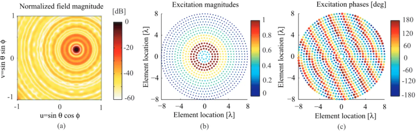
![Fig. 2. Synthesis of an isophoric array by fitting the focused beam pattern of [3]. (a) Fitted and reconstructed radiation patterns, they are superimposed.](https://thumb-eu.123doks.com/thumbv2/123doknet/8184554.274788/5.892.541.770.74.482/synthesis-isophoric-fitting-focused-reconstructed-radiation-patterns-superimposed.webp)

Documents relatifs
For the non adaptive case (top plot), the range of values of λ that achieve high probability of correct rank selection does not increase when n increases and stays bounded, in
L’archive ouverte pluridisciplinaire HAL, est destinée au dépôt et à la diffusion de documents scientifiques de niveau recherche, publiés ou non, émanant des
We propose a sparse signal reconstruction algorithm from interlaced samples with unknown offset parameters based on the l 1 -norm minimization principle.. A
[r]
means that the pattern of a superconducting element is positioned in a multidimensional feature space, that is spanned by all physical and chemical data,
Keywords: k-support norm, structured sparsity, regularization, least-squares, hinge loss, support vector machine, SVM, regularized logistic regression, Ad- aBoost, support
Finally, while these compliance measures are designed to make sense with respect to known results in the area of sparse recovery, one might design other compliance measures tailored
Diffuse noise robust multiple source localization based on matrix completion via trace norm minimization.. Nobutaka Ito, Emmanuel Vincent, Nobutaka Ono, Rémi Gribonval,
